Pure Storage ActiveCluster in conjunction with VMware: review and testing
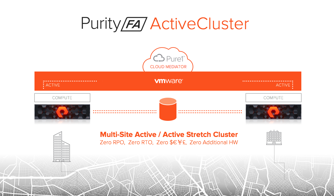
Not so long ago, Pure Storage announced a new ActiveCluster functionality - an active / active metro cluster between data warehouses. This is a synchronous replication technology, in which a logical volume is stretched between two storages and is read / write accessible to both. This functionality is available with the new version of the firmware Purity // FA 5 and is absolutely free. Also, Pure Storage was promised that setting up a stretched cluster has never been so easy and understandable.
In this article we will tell about ActiveCluster: what it consists of, how it works and is configured. In part, the article is a translation of official documentation. In addition, we will share the experience of testing it for fault tolerance in a VMware environment.
Competitive decisions
The presented functionality is not something innovative, similar solutions exist for most major storage vendors: Hitachi GAD (Global Active Device), IBM HyperSwap, HPE 3PAR Peer Persistance, Fujitsu Storage Cluster, Dell Compellent Live Volume, Huawei HyperMetro .
')
However, we decided to highlight some advantages of ActiveCluster compared to competitive solutions:
- Does not require additional licenses. Functionality is available out of the box.
- Simple replication management (we tried - it is really convenient and easy).
- Cloud pick (Quorum device). Does not require a third site and the deployment of a quorum server on it.
ActiveCluster Overview
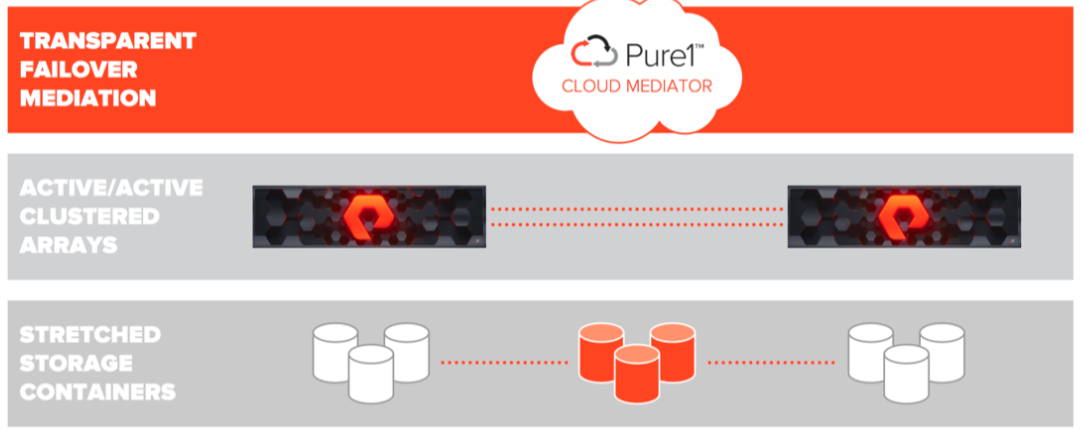
Consider the components that make up ActiveCluster:
- Transparent Failover Mediation . Cloud Mediator is a server / device quorum that decides which of the arrays will continue to work and provide access to the data, and which should stop working in case of various failures.
- Active / Active Clustered Arrays — PureStorage arrays with configured synchronous replication between them. Provide access to a consistent copy of data from one array or from another.
- Stretched Storage Containers - containers containing objects that must be replicated between two arrays.
New objects appeared in ActiveCluster - Pods. Pod is a container containing other objects. If there is a replication channel between two arrays, then several arrays can be added to the pod and then all the objects in this pod will be replicated between the arrays. Stretched pods can be controlled from any array.
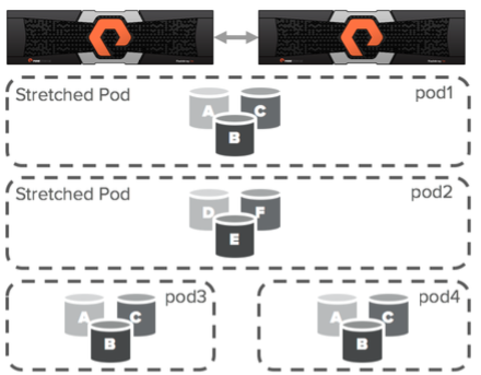
Pods may contain volumes, snapshots, protection groups, and other configuration information. Pod functions as a consistency group, that is, it guarantees a consistent order of recording volumes in one pod.
ActiveCluster: array access schemes for hosts
Access to data hosts can be configured with two access models: uniform and non-uniform. In the uniform model, each host on both sites has access to both arrays for reading / writing. In a non-uniform model, each host has access only to a locally located array for read / write.
Uniform access model
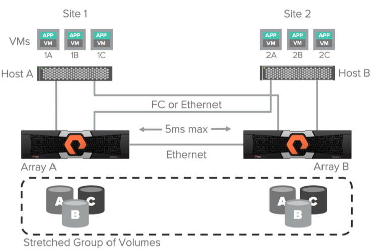
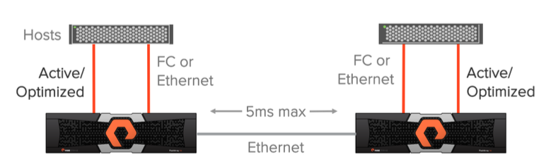
A uniform data access model can be used in environments where Fiber Channel or Ethernet (iSCSI) is used to connect hosts to arrays and Ethernet connection (10g) for replication is used between arrays. In this configuration, the host has access to data through both arrays: both via local and remote. This solution is only supported with a maximum delay between arrays across replication channels of 5 ms.

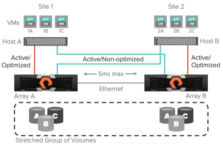
The diagram above illustrates the logical paths from hosts to arrays, as well as the replication channel between arrays in the Uniform access scheme. It is assumed that the data is available to both hosts regardless of the site on which they are located. It is important to understand that the paths to the local array will have less delay than to the remote one.
Optimized performance when using a uniform model
For better I / O performance when using active / active synchronous replication, the host should not use paths to the remote array. For example, consider the picture below. If “VM 2A” performs a write operation on volume “A” using an array “Array A”, then this write operation will entail a double delay in the transmission of data through the replication channel, as well as a delay from the host to the remote array.
I propose to disassemble in more detail. Suppose that the delay on the replication channel between arrays is 3ms. In case of “Host B” connection <-> “Array B”, 1ms delay. And in the case of “Host B” <-> “Array A” - 3ms. A write command will be sent from the “VM 2A” host to the remote site to the “Array A” array with a delay of 3ms. Further, the write command will be sent via the replication channel to the Array B array with a delay of 6ms (3ms + 3ms). After that, a successful write response will be sent back from the Array B array to the Array A array via the replication channel (6ms + 3ms = 9ms). Then the answer about the successful recording will be sent back to the host “VM 2A” (9ms + 3ms = 12ms). Total we get a delay of 12ms per write operation in the case of using a remote array. If we calculate exactly the same principle as using a local array, then we get 8ms.
ActiveCluster allows you to use ALUA (Asymmetric Logical Unit Access) to provide paths to local hosts as active / optimized and to provide paths to remote hosts as active / non-optimized. The optimal path is determined for each host <-> volume bind by setting the preferred array option. Thus, it does not matter which of the hosts your application or virtual machine is running on, the host will always know which array is local for it (it has the best paths), and which remote (it does not have the best paths).
Using ActiveCluster, you can configure truly active / active data centers, without worrying about which platform your virtual machine or application is running on. All read / write operations will always go through the array local to the host.
Non-uniform access model
The non-uniform access model is also used in environments where Fiber Channel or Ethernet (iSCSI) is used to connect hosts to arrays. In this model, the hosts have access only to the local array and do not have access to the remote array. This solution also involves the use of replication connections between arrays with a delay of no more than 5ms.
Pros and cons of these access models
The Uniform access model provides a higher level of fault tolerance, since the failure of one array does not entail restarting the virtual machines or applications that used this array — data access will continue through the other. Of course, this model assumes a working and configured multipathing (multipathing) on the host side, which would distribute I / O requests over active / optimized paths and active / non-optimized in the case when the first ones are unavailable.
In the case of using the Non-uniform model, the hosts have access only to the local array and, accordingly, only by active / optimized paths. If a local array fails, all virtual machines or applications will lose access to data on this site and will be restarted (for example, using VMware HA tools) on another site using data access through another array.
Configure Active Cluster
The guys from Pure Storage declare a very simple, intuitive configuration of ActiveCluster. Well, let's see. Setup is done in 4 steps:
Step 1 : Connect two Flash arrays.
We connect our arrays with two Ethernet 10Gb / s channels and configure the type of connection as Sync Replication via GUI.

Step 2 : Creating and Stretching pod.
To create a pod, we will use the CLI (through the GUI, too, is possible). The purepod command is used to create and stretch pod. As we said earlier, pod is a container that is designed to simplify management in an active / active environment. Pod determines which objects should synchronously replicate between arrays. You can manage stretched pods and objects in them from any of the arrays. Pods may contain volumes, snapshots, clones, group protection and other configuration information.
Create a pod on the Array A array:
arrayA> purepod create pod1Stretch the pod on Array B:
arrayA> purepod add --array arrayB pod1Now, any volumes, snapshots or clones placed in this pod will automatically replicate between the Array A and Array B arrays.
Step 3 : Creating Volumes
On any of the arrays we create a volume vol1 of 1TB size and place it in pod1:
> purevol create --size 1T pod1::vol1Instead of creating a volume, we can move any already existing volume to pod1 and it will begin to replicate.
Step 4 : Presentation of the volume to the host.
Once again, we note that ActiveCluster is a real active / active solution that allows you to read and write to the same logical volume using both arrays.
Create a host and present volume vol1 to this host:
> purehost create --preferred-array arrayA --wwnlist <WWNs f ESX-1 >
> purehost connect --vol pod1::vol1 ESX-1
Please note that we specify the option –preferred-array, which means that the paths from the ArrayA array will be optimal for this host (active / optimized).
It's all! Now ESX-1 has access to vol1 through both the ArrayA and ArrayB arrays. Quick and easy, isn't it?
Additionally, check the status of the mediator. We use the cloud mediator Pure, to access it arrays must have access to the Internet. If the security policy does not allow this, then it is possible to download and deploy a local mediator.
purepod list --mediator
Name Source Mediator Mediator Version Array Status Frozen At Mediator Status
pod1 - purestorage 1.0 Array-A online – online
Array-B online - online
Functional testing of ActiveCluster in VMware environment
We were faced with the task of functional testing of a bunch of two Flash Array // m20 in ActiveCluster and VMware configuration (2 ESX hosts) in terms of ensuring the fail-safe operation of virtual machines. We emulated the presence of two sites, each of which had an ESX host and a Flash Array. The version used is VMware 6.5 U1 and version Pure // FA 5.0.1.
We had the following success criteria:
- Emulated disk array failures do not interrupt virtual machines.
- Emulated failures of the ESX server allow you to automatically (using VMware HA) run virtual machines on another ESX server.
- Emulated site failures (array + esx server) allow automatically (using VMware HA) to start virtual machines on another site.
- Test vMotion in configuration with VMware + ActiveCluster.
The scheme of our stand is presented below:

ActiveCluster was built between the m20 # 1 and m20 # 2 arrays using a 10 Gbps replication channel. A pod was created on one array, and then stretched by adding a second array to it. On both arrays, a 200GB volume was created and added to the stretched pod, thereby starting replication of these volumes between arrays. The replicated volume was presented to both ESX hosts using the Uniform access scheme with the preferred array configuration for host groups. For the ESX1 host, the preferred array was m20 # 1, and for ESX2, the corresponding m20 # 2. Thus, from the side of the ESX hosts, the paths to the datastores were active (I / O optimized) to the local array and active (non-optimized) to the remote one.
Emulation of disk array failure
For testing, a virtual machine with Windows 2012 r2 was installed. VM files were located on a shared datastore on a stretched volume with Pure Storage. Also in this VM, another 100GB disk was presented from the same datastore, to which we launched a synthetic load using IOmeter. I note that we didn’t have a goal to measure performance, we had to generate any I / O activity so that during our tests we could catch moments when SCSI read / write commands could hang when switching paths to arrays.
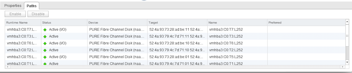
So, everything is ready: the test VM runs on ESX1, the ESX1 host uses the optimal paths to the m20 # 1 array for I / O operations. We go to the server room and chop off the m20 # 1 array on power and monitor the IOmeter in the VM. No interruption in input / output occurs. We look at the state of the paths to the datastor: the paths to m20 # 1 are in the dead state, the paths to m20 # 2 are switched to the active (I / O) state. The test was conducted several times with slightly different inputs, but the result was always successful. We consider the test successfully passed.
PS After turning on the m20 # 1 array, the paths switched back to it, that is, to the site local to this ESX host.
ESX host failure emulation
This test is not very interesting, as we, in fact, do not check Pure Storage, but the operation of VMware HA. In any case, we expected a downtime for the VM and its subsequent resurrection by a cluster on another ESX host.
In general, we went to the server room and pulled the power supply host ESX1. VMware HA worked properly, and our VM successfully went up on the ESX2 host. The test is considered successful.
Emulation of the entire site failure
In fact, this is the first and second test conducted simultaneously. And in any case, this is downtime for the virtual machine, since we disable the ESX host. The source data is the same as in the first test: the VM runs on ESX1, the ESX1 host uses the m20 # 1 for I / O, the VM runs the IOmeter for the synthetic load on the array.
We go to the server and turn off the power at ESX1 and m20 # 1. We are watching. Within 1-2 minutes, VMware HA raises the virtual machine on ESX2, the paths on ESX2 are in the dead state for m20 # 1 and in the active (I / O) state for the m20 # 2 array. The test is considered successful.
Verify vMotion performance in ActiveCluster configuration
A very formal test. We needed to check that it works and there are no pitfalls. We drove vMotion both on the enabled virtual machine and on the off, with and without a datastor change, no problems were revealed. Test passed successfully.
Conclusion
Synchronous replication technology is no longer new and almost every major storage vendor has one, but Pure Storage stands out among them because it does not require additional licenses to use it, which can often make up a large part of the cost of the storage itself. Also, the guys from Pure have brought a new level of convenience to managing replication, now there is no need to study dozens of pages of documentation in order to configure it, and the whole process is intuitive. In order to increase our own competencies, we also conduct various tests both at home and at customers within the framework of the organization Proof of Concept. Together with the OCS distributor (we took the second array from them), we deployed the first Pure Storage ActiveCluster in Russia, where we tested.
Sergey Surnin, expert of the Jet Infosystems Service Center
Source: https://habr.com/ru/post/359076/
All Articles