Remote control of the heating system
The Internet of Things (IoT, Internet of Things) is a promising area, as analysts say. One of the main trends of IoT is home automation or, as marketers like to say, the creation of a “smart home”.
Let's leave the verbal exercises alone and consider a specific project.
I live in my own home near Moscow. In addition to the obvious advantages of this accommodation option, there are some nuances. If in an apartment building the majority of utility tasks are taken over by the management company, then in their own home they have to be solved independently.
One of these tasks for me was the need for remote monitoring and control of the heating system. It is true that in central Russia heating in the winter is not a matter of comfort, but of survival. According to the repeatedly confirmed empirical law, all troubles happen at the most inappropriate time. For more than a decade of experience in my own home, I also became convinced of the validity of this law.
')
But if, for example, the failure of the water supply pump in a 30-degree frost can somehow be survived, then the failure of the heating boiler turns into a catastrophe. In such a frost, a normally warmed house is wiped out in less than a day.
I often have to leave home for a long time, including in winter. Therefore, the possibility of remote monitoring of the state of the heating system and its management has become an urgent task for me.
In my house, the heating system has two boilers, solar (alas, there is no gas and is not foreseen) and electric. This choice is due not only to issues of reservation, but also to optimize the cost of heating. At night, with the exception of severe frosts, the electric boiler works, as the house has a double tariff meter. The power of this boiler is enough for a comfortable night temperature (18-19 degrees). In the daytime, the solar boiler enters the work, raising the temperature to 22-23 degrees. In this mode, the heating system has been operating for several years and allows us to conclude that this option is economical.
It is clear that the daily manual switching of the heating system operation modes is not the most reasonable choice, so the decision was made to automate this process and, at the same time, provide for the possibility of remote control.
Following the developer’s habit, the first thing I did was to systematize the requirements for the control system being created and put something like a technical task for myself.
Here is a brief list of the basic requirements for the projected solution:
Initially, the list had a few more items, but then they were excluded for various reasons. For example, I planned to equip the system with a screen with an indication of the current parameters and the ability to control through the touchscreen. But it seemed to me not necessary duplication of remote control via the Internet. Of course, you can come up with quite life situations when local indication and control are necessary. I do not argue, but do not forget that this opportunity would require additional complication and increase in the cost of the system.
The algorithm of control of the heating system contains the apocalypse scenario associated with a complete power outage. It is clear, in this case it is not necessary to talk about remote control. But those who are in the house can go into emergency heating mode with a few simple manipulations. It is enough to switch one external four-pole toggle switch and start the backup gasoline electric generator. This will ensure the operation of the solar boiler offline. In practice, this has already happened a couple of times, when the freezing rain has led to a massive break in the power lines.
Modern heating boilers, as a rule, have remote control units that are connected by a conventional twin wire. In order not to get into the factory control schemes, it was decided to switch these wires themselves. A wire break caused by a conventional electromechanical relay causes the boiler to stop working.
Having read horror stories about the consequences of hacking smart homes, I decided to insure and minimize the possibility of external hacking. Someone will say, they say, who needs to break open your smart home. I agree, the probability is minimal, but watching regular attempts at hacking my web servers, I decided to act according to the principle: it is better to sleep than not to finish. Joke.
For this, I abandoned the common paradigm, when the central server is the initiator of managing distributed smart sensors (devices). It was decided to use the classic client-server scheme, where the client is a smart sensor.
The choice of such an architecture is not always possible in IoT, but in this case it is quite acceptable, since the heating systems have a sufficiently large inertia. Even the presence of the possibility of instantaneous and arbitrary change of settings in the system, for example, the value of the temperature in the room, does not lead to an instantaneous achievement of the specified parameters.
The transfer of initiative in the exchange of data to the side of the smart sensor makes it possible to almost completely eliminate its hacking by unauthorized persons. After all, the sensor only receives a response from the server to its request. Theoretically, you can intercept such a request and replace the answer, but this threat is minimized, for example, with the https protocol. If there is no desire to raise this protocol in the sensor, then there is an option with the calculation of checksums taking into account the parameters, a priori unknown to the attacker. But this cryptographic question is beyond the scope of this topic.
If the request was not received a response from the server, the smart sensor, after waiting for a certain time-out, continues to work in the previously set mode.
As a server, it was decided to create a small website with a MySQL database, which was deployed on a third-level domain of one of my sites. The site was written using an adaptive layout that allows you to comfortably work with your smartphone.
For the exchange of information with the server was selected a five-minute period.
In part, this choice is due to one nuance of the electric boiler. To exclude boiling of water in the heater flask from residual heat of heating elements, the so-called boiler run-down is used. In other words, after turning off the heating element, the circular pump continues to operate for a while. In my boiler, the default run is 4 minutes, although it can be increased for a longer time. Therefore, the five-minute interval of exchange is well within the logic of the heating system. Yes, and more frequent data exchange did not give any benefit, only led to an increase in the number of records in the server database.
The operation of the smart sensor, called the weather module, does not contain anything unusual. In the cycle temperature and humidity sensors are polled. It takes about 4.5 minutes. Then a GET request to the server is generated and the received response is processed. As a result, the period (main cycle) is obtained with a duration of about 5 minutes. It does not require perfect accuracy, in practice, the period was less than a few seconds, which leads to a gradual shift. With an ideal five-minute period per day, 288 samples would be transmitted, in reality, 289–290 of them appear. This does not affect the system at all.
The main sketch of the program with detailed comments is given in the listing. Due to the vast amount of code I did not publish the implementation of the used subroutines. The listing left diagnostic messages for output to the terminal.
As I mentioned above, there are three modes of operation in the weather module:
In automatic mode, the weather module selects which boiler to turn on at one time or another according to the built-in real-time clock. At the time of a reduced tariff for electricity, an electric boiler is started.
In the original version of the system, it was possible to operate the electric boiler in the same daytime period in order to save diesel fuel. In this variant, the weather module tracked the operation time of the electric boiler during the day. If within an hour it was not possible to reach the set temperature in the house, then the electric boiler was turned off and after a pause to run out, the solar boiler was turned on.
According to the experience of the first winter, this option was removed. The reason was the lack of power of the electric boiler, which could not in relatively severe frosts (below -10 degrees) ensure the achievement of a given comfortable temperature. Therefore, it was decided during the day to launch the solar boiler unambiguously in automatic mode.
Semi-automatic mode implies a hard choice of one or another boiler with maintaining automatic adjustment of its operation according to the temperature sensors of the weather module. This mode has proven useful in several cases. Firstly, when one boiler fails, the operation of another boiler is forcibly set, regardless of the time of day. Secondly, in weak frosts and thaws, the electric boiler can be turned on around the clock, or, conversely, only solar boilers can be started at very cold frosts.
I practically do not use manual mode. It implies not only the selection of a specific boiler for operation, but also the transfer of control to the staff remote unit. In other words, the boiler will be controlled by the specified temperature parameters on this unit. The weather module in this mode continues to operate only as a station for monitoring temperature and humidity.
In its request to the server, the weather module transmits a data packet that includes information about the current state of the boilers (which boiler is selected, running or not), the current local time of the weather module, the duration of boiler operation in the preceding five-minute period, the current temperature and humidity inside and outside the house. Also, the request includes the identifier of the weather module. In my case, this is unnecessary, but the habit of designing for scaling has made itself felt.
After sending the request, the weather module waits for the server to respond for 20 seconds. The resulting response is parsed using regular expressions. There are four parameters in the server response:
In the current version, the outside temperature threshold is not used. This possibility was provided for the implementation of the choice of heating patterns, depending on the temperature "overboard". Probably, this function sometime I implement.
The last parameter is required quite rarely. I asked him only twice. During the initial launch of the module and after replacing the battery in the real time clock module. If the temporary settings do not require a change, then this parameter is zero.
After parsing the response from the server, the current timers for the boilers are reset. After all, the previous value has already been sent to the server. The reset takes into account the pause time waiting for a response from the server.
It should be noted that the transmitted time of the boiler has an estimated value. According to this parameter it is impossible to judge, say, the consumed electricity. This is due to the peculiarities of the heating boilers. For example, when the temperature in the boiler reaches 80 degrees, it switches off, but the circular pump continues to operate. By reducing the temperature of the coolant to 60 degrees, the boiler is again included in the work. The weather module only measures the total time it took for the boiler to reach the temperature threshold inside the house.
After reaching the set temperature, the boiler is turned off, and the meteorological module continues to read temperature indicators with a frequency of 30 seconds. When the temperature drops by more than 0.5 degrees, the heating boiler is re-activated. This hysteresis was chosen experimentally, taking into account the inertia of the heating system.
For visual indication of the performance of the weather module in the subroutine of the delay between cycles of temperature measurement, the flashing of the built-in LED has been added.
I want to note that the choice of the mode of operation of the boiler occurs at the end of a five-minute period. When the module is initially turned on or when it is restarted, the default mode is automatic.
To translate the idea, I used what was at hand. It was decided to build a weather module using Arduino modules. Mega 2560, which remained from previous experiments, was taken as a processor board. This fee is obviously redundant for this task, but it was available. In addition to it was the layout of the layout, which housed almost all the other modules. This is a DS3231 real-time clock and ESP8266 WiFi module (01). A switching unit with two relays was purchased for separate control of electric and solar boilers.
As the power source used the existing computer power supply. As is known, in such a unit there is a wide choice of secondary supply voltage. There is + 5V and, which is especially important when working with the ESP8266 WiFi module, + 3.3V. In addition, these units are very reliable, taking into account the continuous nature of the weather module.
The figure shows the circuit switching boards. The schematic diagram was not drawn in view of its obviousness. The figure has an RGB-LED for visual indication of the operating modes of the weather module. Green color indicates that the boilers are switched off, red means the operation of the solar boiler, blue - electric. I did not have 220 Ohm resistors at hand, so the RGB-LED was connected directly to the outputs of the board, without current-limiting resistors. I repent, I was wrong, but I took the risk consciously. The current consumption of each output LED is only 20 mA, the output of the board allows you to connect up to 40 mA. For three years of operation, while there were no problems.
DHT21 (AM2301) were used as temperature sensors. Initially, the DHT11 sensor was used to measure the temperature inside the house, but it has very poor measurement accuracy and, for an unexplained reason, the DTH.h library did not work correctly when using two different types of sensors in the circuit. But since the replacement of the DHT11 due to its excessive error was obvious, I did not begin to deal with the library problem.
The numbers in the boxes mean the numbers of the wires that connect external devices to the main board.
The entire scheme was assembled in a hinged metal shield used for the installation of electrical wiring. The choice of such a body was also related to what was at hand.
But here I was expecting quite predictable surprise. With the door completely closed, the casing body shielded the WiFi signal. I had to leave the door ajar, as there was no desire to look for another suitable case and re-mount everything. So I live for three years with the door ajar.
The web server used for monitoring and management is written in pure PHP and has an adaptive layout. Initially, there was an idea to write an application for Android, but I refused this idea, as all the same the server would be necessary.
After authorization, several pages with information become available. This is the current state of the system according to the last received request from the weather module, a table of values in the current hour and a graphical representation of the summary information for an arbitrary period of time. There is also a page with a choice of settings for controlling the weather module.
At the time of this writing, the meteorological module was already turned off, because the heating season was over. Therefore, all the parameters on the main page of the site are relevant at the time of shutdown. An attentive reader will notice that it was May 2nd.

As an example of graphs, the values for January 25, 2018 are given. Histograms show boilers running time.


Setup Page
As I already mentioned, this solution for monitoring and controlling the heating system of a private house has already worked three heating seasons. During this time there were only two freezes caused by the long-term disappearance of the channel to the Internet. And not the whole meteorological module was hanging, but only the ESP8266 WiFi module.
In general, the functionality of the system completely suits me, but given the apparent redundancy of the applied platform, I am thinking about expanding it.
Let's leave the verbal exercises alone and consider a specific project.
Formulation of the problem
I live in my own home near Moscow. In addition to the obvious advantages of this accommodation option, there are some nuances. If in an apartment building the majority of utility tasks are taken over by the management company, then in their own home they have to be solved independently.
One of these tasks for me was the need for remote monitoring and control of the heating system. It is true that in central Russia heating in the winter is not a matter of comfort, but of survival. According to the repeatedly confirmed empirical law, all troubles happen at the most inappropriate time. For more than a decade of experience in my own home, I also became convinced of the validity of this law.
')
But if, for example, the failure of the water supply pump in a 30-degree frost can somehow be survived, then the failure of the heating boiler turns into a catastrophe. In such a frost, a normally warmed house is wiped out in less than a day.
I often have to leave home for a long time, including in winter. Therefore, the possibility of remote monitoring of the state of the heating system and its management has become an urgent task for me.
In my house, the heating system has two boilers, solar (alas, there is no gas and is not foreseen) and electric. This choice is due not only to issues of reservation, but also to optimize the cost of heating. At night, with the exception of severe frosts, the electric boiler works, as the house has a double tariff meter. The power of this boiler is enough for a comfortable night temperature (18-19 degrees). In the daytime, the solar boiler enters the work, raising the temperature to 22-23 degrees. In this mode, the heating system has been operating for several years and allows us to conclude that this option is economical.
It is clear that the daily manual switching of the heating system operation modes is not the most reasonable choice, so the decision was made to automate this process and, at the same time, provide for the possibility of remote control.
Technical task
Following the developer’s habit, the first thing I did was to systematize the requirements for the control system being created and put something like a technical task for myself.
Here is a brief list of the basic requirements for the projected solution:
- control the temperature in the house and outside
- provide three modes of choice of heating boilers (more details below)
- provide remote monitoring of the state of the system and its management
Initially, the list had a few more items, but then they were excluded for various reasons. For example, I planned to equip the system with a screen with an indication of the current parameters and the ability to control through the touchscreen. But it seemed to me not necessary duplication of remote control via the Internet. Of course, you can come up with quite life situations when local indication and control are necessary. I do not argue, but do not forget that this opportunity would require additional complication and increase in the cost of the system.
The algorithm of control of the heating system contains the apocalypse scenario associated with a complete power outage. It is clear, in this case it is not necessary to talk about remote control. But those who are in the house can go into emergency heating mode with a few simple manipulations. It is enough to switch one external four-pole toggle switch and start the backup gasoline electric generator. This will ensure the operation of the solar boiler offline. In practice, this has already happened a couple of times, when the freezing rain has led to a massive break in the power lines.
Modern heating boilers, as a rule, have remote control units that are connected by a conventional twin wire. In order not to get into the factory control schemes, it was decided to switch these wires themselves. A wire break caused by a conventional electromechanical relay causes the boiler to stop working.
IoT security method
Having read horror stories about the consequences of hacking smart homes, I decided to insure and minimize the possibility of external hacking. Someone will say, they say, who needs to break open your smart home. I agree, the probability is minimal, but watching regular attempts at hacking my web servers, I decided to act according to the principle: it is better to sleep than not to finish. Joke.
For this, I abandoned the common paradigm, when the central server is the initiator of managing distributed smart sensors (devices). It was decided to use the classic client-server scheme, where the client is a smart sensor.
The choice of such an architecture is not always possible in IoT, but in this case it is quite acceptable, since the heating systems have a sufficiently large inertia. Even the presence of the possibility of instantaneous and arbitrary change of settings in the system, for example, the value of the temperature in the room, does not lead to an instantaneous achievement of the specified parameters.
The transfer of initiative in the exchange of data to the side of the smart sensor makes it possible to almost completely eliminate its hacking by unauthorized persons. After all, the sensor only receives a response from the server to its request. Theoretically, you can intercept such a request and replace the answer, but this threat is minimized, for example, with the https protocol. If there is no desire to raise this protocol in the sensor, then there is an option with the calculation of checksums taking into account the parameters, a priori unknown to the attacker. But this cryptographic question is beyond the scope of this topic.
If the request was not received a response from the server, the smart sensor, after waiting for a certain time-out, continues to work in the previously set mode.
As a server, it was decided to create a small website with a MySQL database, which was deployed on a third-level domain of one of my sites. The site was written using an adaptive layout that allows you to comfortably work with your smartphone.
For the exchange of information with the server was selected a five-minute period.
In part, this choice is due to one nuance of the electric boiler. To exclude boiling of water in the heater flask from residual heat of heating elements, the so-called boiler run-down is used. In other words, after turning off the heating element, the circular pump continues to operate for a while. In my boiler, the default run is 4 minutes, although it can be increased for a longer time. Therefore, the five-minute interval of exchange is well within the logic of the heating system. Yes, and more frequent data exchange did not give any benefit, only led to an increase in the number of records in the server database.
Work algorithm
The operation of the smart sensor, called the weather module, does not contain anything unusual. In the cycle temperature and humidity sensors are polled. It takes about 4.5 minutes. Then a GET request to the server is generated and the received response is processed. As a result, the period (main cycle) is obtained with a duration of about 5 minutes. It does not require perfect accuracy, in practice, the period was less than a few seconds, which leads to a gradual shift. With an ideal five-minute period per day, 288 samples would be transmitted, in reality, 289–290 of them appear. This does not affect the system at all.
The main sketch of the program with detailed comments is given in the listing. Due to the vast amount of code I did not publish the implementation of the used subroutines. The listing left diagnostic messages for output to the terminal.
The main sketch of the program
/* * Sketch Meteo Control Mega2560 * ver. 13.0 * - , - . 21 , - 0,5 * http 1.0 */ // libs #include <Wire.h> #include "DHT.h" // wired connections // I2C, 104 #define DS3231_I2C_ADDRESS 104 // define #define HYSTERESIS 0.5 // , #define LONG_CYCLE 9 // , 9 - 5 #define SHORT_CYCLE 13 // , 13 . 30 #define DAY_BEGIN 6 // #define DAY_END 22 // #define MIN_INTERVAL 3000 // 3 #define PIN_DHT_IN 23 // AM2301 #define PIN_DHT_OUT 22 // AM2301 #define DHTTYPE DHT21 DHT dhtin(PIN_DHT_IN, DHTTYPE); DHT dhtout(PIN_DHT_OUT, DHTTYPE); #define RELAY_E 25 // #define RELAY_D 24 // #define LED_R 27 // LED RGB #define LED_G 29 // LED RGB #define LED_B 31 // LED RGB #define LED 13 // #define LEAP_YEAR(_year) ((_year%4)==0) // // vars uint32_t workTime; // float hIn; // float tIn; // float hOut; // float tOut; // float tModule; // float tInSet; // float tOutSet; // . . byte seconds, minutes, hours, day, date, month, year; byte del; // , char weekDay[4]; byte tMSB, tLSB; float temp3231; static byte monthDays[] = {31, 28, 31, 30, 31, 30, 31, 31, 30, 31, 30, 31}; uint32_t unixSeconds; // UNIX uint16_t timeWorkElectro; // () uint16_t timeWorkDiesel; // () uint32_t unixSecondsStartCycle; // UNIX int modeWork; // , 0 - auto, 1 - -, 2 - -, 3 - -, 4 - -, 5 - - byte typeBoiler; // , 0 - , 1 - , 2 - char statusBoiler; // char unit = '1'; // id char mode; // String message; // char ans; // String answerServer; // String tInSer; // = String tOutSer; // = String timeSer; // = char datetime[15]; // void setup() { Serial.begin(115200); // COM Serial.println("Start setup()"); Serial.println("Meteo Module. Ver.13.0 Unit Number: " + String(unit)); pinMode(LED, OUTPUT); //LED flash pinMode(LED_R, OUTPUT); //LED_R pinMode(LED_G, OUTPUT); //LED_G pinMode(LED_B, OUTPUT); //LED_B // Wire.begin(); //set control register to output square wave on pin 3 at 1Hz Wire.beginTransmission(DS3231_I2C_ADDRESS); // 104 is DS3231 device address Wire.write(0x0E); Wire.write(B00000000); Wire.write(B10001000); Wire.endTransmission(); // tInSet = 21; tOutSet = -15; // pinMode(PIN_DHT_OUT, INPUT_PULLUP); dhtout.begin(); // pinMode(PIN_DHT_IN, INPUT_PULLUP); dhtin.begin(); // pinMode(RELAY_E, OUTPUT); pinMode(RELAY_D, OUTPUT); modeWork = 0; // // relayElectroSwitchOff(); relayDieselSwitchOff(); timeWorkElectro = 0; // timeWorkDiesel = 0; unixSecondsStartCycle = 0; // typeBoiler = 0; Serial.println("All Boilers Off"); digitalWrite(LED_G, HIGH); // RGB-. , // serial 1 is to esp8266 Serial1.begin(115200); // ESP8266 Serial1.setTimeout(1000); while (!Serial1); String startcommand = "AT+CWMODE=1"; // ESP8266 Serial1.println(startcommand); Serial.println(startcommand); delay(2000); del = 0; // } void loop() { Serial.print("Start loop(). "); // get3231Date(); // unixSeconds = timeUnix(seconds, minutes, hours, date, month, year); // UNIX- Serial.print("Current datetime: "); Serial.print(weekDay); Serial.print(", "); if (date < 10) Serial.print("0"); Serial.print(date, DEC); Serial.print("."); if (month < 10) Serial.print("0"); Serial.print(month, DEC); Serial.print("."); Serial.print(year, DEC); Serial.print(" - "); if (hours < 10) Serial.print("0"); Serial.print(hours, DEC); Serial.print(":"); if (minutes < 10) Serial.print("0"); Serial.print(minutes, DEC); Serial.print(":"); if (seconds < 10) Serial.print("0"); Serial.println(seconds, DEC); // Serial.println("Getting temperature and himidity"); getSensors(); // collectServerData(); // // Serial.println("Send data to server"); connectServer(); // controlServer(); // switch(modeWork){ case 0: // Serial.println("Current Mode: Auto"); autoMode(); break; case 1: // Serial.println("Manual Mode"); manualMode1(); break; case 2: // Serial.println("Manual Mode"); manualMode2(); break; case 3: // Serial.println("Manual Mode"); manualMode3(); break; case 4: // Serial.println("Semi Auto Mode Electro"); semiAutoMode4(); break; case 5: // Serial.println("Semi Auto Mode Diesel"); semiAutoMode5(); break; } del = LONG_CYCLE; // while (del > 0) { Serial.print("Start short cycle #"); Serial.println(del); // mDelay(SHORT_CYCLE); // Serial.println("Getting temperature and himidity"); getSensors(); del--; // } } As I mentioned above, there are three modes of operation in the weather module:
- auto
- semi-automatic
- manual
In automatic mode, the weather module selects which boiler to turn on at one time or another according to the built-in real-time clock. At the time of a reduced tariff for electricity, an electric boiler is started.
In the original version of the system, it was possible to operate the electric boiler in the same daytime period in order to save diesel fuel. In this variant, the weather module tracked the operation time of the electric boiler during the day. If within an hour it was not possible to reach the set temperature in the house, then the electric boiler was turned off and after a pause to run out, the solar boiler was turned on.
According to the experience of the first winter, this option was removed. The reason was the lack of power of the electric boiler, which could not in relatively severe frosts (below -10 degrees) ensure the achievement of a given comfortable temperature. Therefore, it was decided during the day to launch the solar boiler unambiguously in automatic mode.
Semi-automatic mode implies a hard choice of one or another boiler with maintaining automatic adjustment of its operation according to the temperature sensors of the weather module. This mode has proven useful in several cases. Firstly, when one boiler fails, the operation of another boiler is forcibly set, regardless of the time of day. Secondly, in weak frosts and thaws, the electric boiler can be turned on around the clock, or, conversely, only solar boilers can be started at very cold frosts.
I practically do not use manual mode. It implies not only the selection of a specific boiler for operation, but also the transfer of control to the staff remote unit. In other words, the boiler will be controlled by the specified temperature parameters on this unit. The weather module in this mode continues to operate only as a station for monitoring temperature and humidity.
In its request to the server, the weather module transmits a data packet that includes information about the current state of the boilers (which boiler is selected, running or not), the current local time of the weather module, the duration of boiler operation in the preceding five-minute period, the current temperature and humidity inside and outside the house. Also, the request includes the identifier of the weather module. In my case, this is unnecessary, but the habit of designing for scaling has made itself felt.
After sending the request, the weather module waits for the server to respond for 20 seconds. The resulting response is parsed using regular expressions. There are four parameters in the server response:
- inside temperature threshold
- threshold temperature outside the house
- set mode
- initial setup time for a real-time clock module
In the current version, the outside temperature threshold is not used. This possibility was provided for the implementation of the choice of heating patterns, depending on the temperature "overboard". Probably, this function sometime I implement.
The last parameter is required quite rarely. I asked him only twice. During the initial launch of the module and after replacing the battery in the real time clock module. If the temporary settings do not require a change, then this parameter is zero.
After parsing the response from the server, the current timers for the boilers are reset. After all, the previous value has already been sent to the server. The reset takes into account the pause time waiting for a response from the server.
It should be noted that the transmitted time of the boiler has an estimated value. According to this parameter it is impossible to judge, say, the consumed electricity. This is due to the peculiarities of the heating boilers. For example, when the temperature in the boiler reaches 80 degrees, it switches off, but the circular pump continues to operate. By reducing the temperature of the coolant to 60 degrees, the boiler is again included in the work. The weather module only measures the total time it took for the boiler to reach the temperature threshold inside the house.
After reaching the set temperature, the boiler is turned off, and the meteorological module continues to read temperature indicators with a frequency of 30 seconds. When the temperature drops by more than 0.5 degrees, the heating boiler is re-activated. This hysteresis was chosen experimentally, taking into account the inertia of the heating system.
For visual indication of the performance of the weather module in the subroutine of the delay between cycles of temperature measurement, the flashing of the built-in LED has been added.
I want to note that the choice of the mode of operation of the boiler occurs at the end of a five-minute period. When the module is initially turned on or when it is restarted, the default mode is automatic.
Implementation
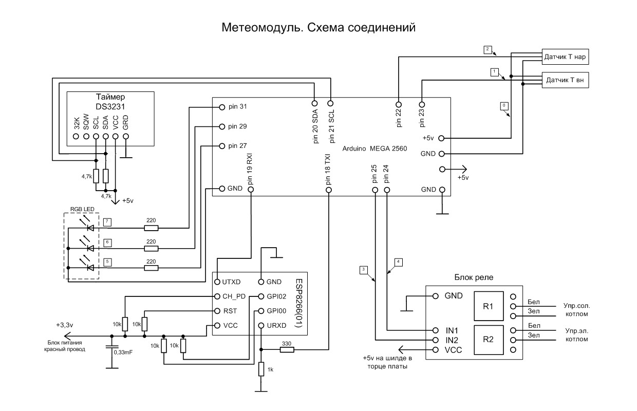
To translate the idea, I used what was at hand. It was decided to build a weather module using Arduino modules. Mega 2560, which remained from previous experiments, was taken as a processor board. This fee is obviously redundant for this task, but it was available. In addition to it was the layout of the layout, which housed almost all the other modules. This is a DS3231 real-time clock and ESP8266 WiFi module (01). A switching unit with two relays was purchased for separate control of electric and solar boilers.
As the power source used the existing computer power supply. As is known, in such a unit there is a wide choice of secondary supply voltage. There is + 5V and, which is especially important when working with the ESP8266 WiFi module, + 3.3V. In addition, these units are very reliable, taking into account the continuous nature of the weather module.
The figure shows the circuit switching boards. The schematic diagram was not drawn in view of its obviousness. The figure has an RGB-LED for visual indication of the operating modes of the weather module. Green color indicates that the boilers are switched off, red means the operation of the solar boiler, blue - electric. I did not have 220 Ohm resistors at hand, so the RGB-LED was connected directly to the outputs of the board, without current-limiting resistors. I repent, I was wrong, but I took the risk consciously. The current consumption of each output LED is only 20 mA, the output of the board allows you to connect up to 40 mA. For three years of operation, while there were no problems.
DHT21 (AM2301) were used as temperature sensors. Initially, the DHT11 sensor was used to measure the temperature inside the house, but it has very poor measurement accuracy and, for an unexplained reason, the DTH.h library did not work correctly when using two different types of sensors in the circuit. But since the replacement of the DHT11 due to its excessive error was obvious, I did not begin to deal with the library problem.
The numbers in the boxes mean the numbers of the wires that connect external devices to the main board.
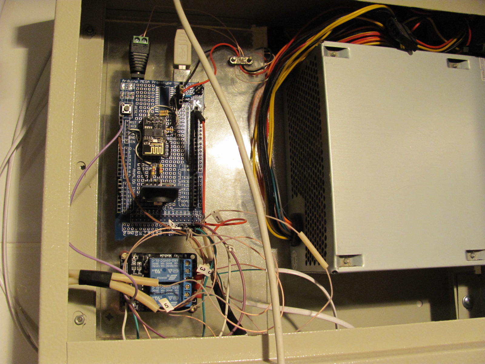
The entire scheme was assembled in a hinged metal shield used for the installation of electrical wiring. The choice of such a body was also related to what was at hand.
But here I was expecting quite predictable surprise. With the door completely closed, the casing body shielded the WiFi signal. I had to leave the door ajar, as there was no desire to look for another suitable case and re-mount everything. So I live for three years with the door ajar.
Management server
The web server used for monitoring and management is written in pure PHP and has an adaptive layout. Initially, there was an idea to write an application for Android, but I refused this idea, as all the same the server would be necessary.
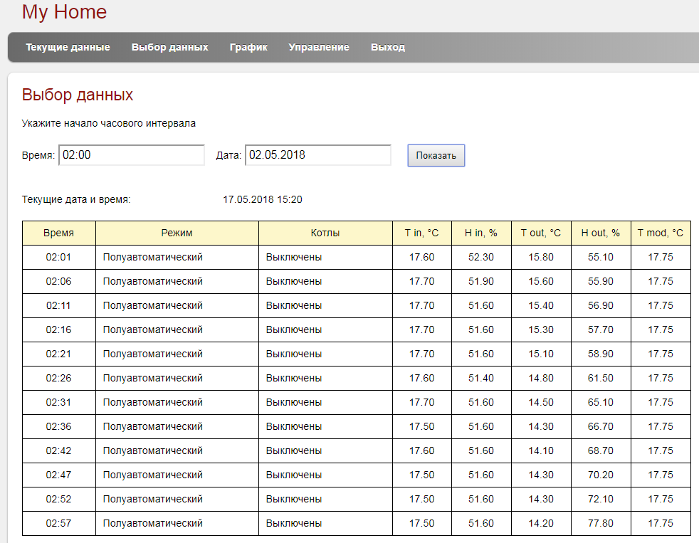
After authorization, several pages with information become available. This is the current state of the system according to the last received request from the weather module, a table of values in the current hour and a graphical representation of the summary information for an arbitrary period of time. There is also a page with a choice of settings for controlling the weather module.
At the time of this writing, the meteorological module was already turned off, because the heating season was over. Therefore, all the parameters on the main page of the site are relevant at the time of shutdown. An attentive reader will notice that it was May 2nd.
As an example of graphs, the values for January 25, 2018 are given. Histograms show boilers running time.
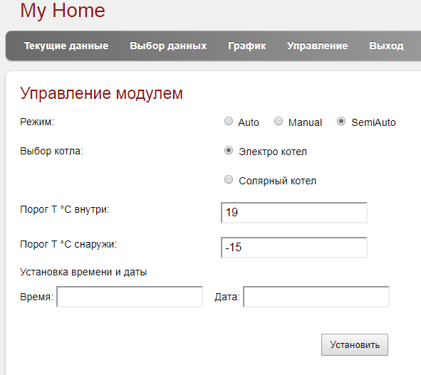
Setup Page
As I already mentioned, this solution for monitoring and controlling the heating system of a private house has already worked three heating seasons. During this time there were only two freezes caused by the long-term disappearance of the channel to the Internet. And not the whole meteorological module was hanging, but only the ESP8266 WiFi module.
In general, the functionality of the system completely suits me, but given the apparent redundancy of the applied platform, I am thinking about expanding it.
Source: https://habr.com/ru/post/358796/
All Articles