How we invented the OTDR
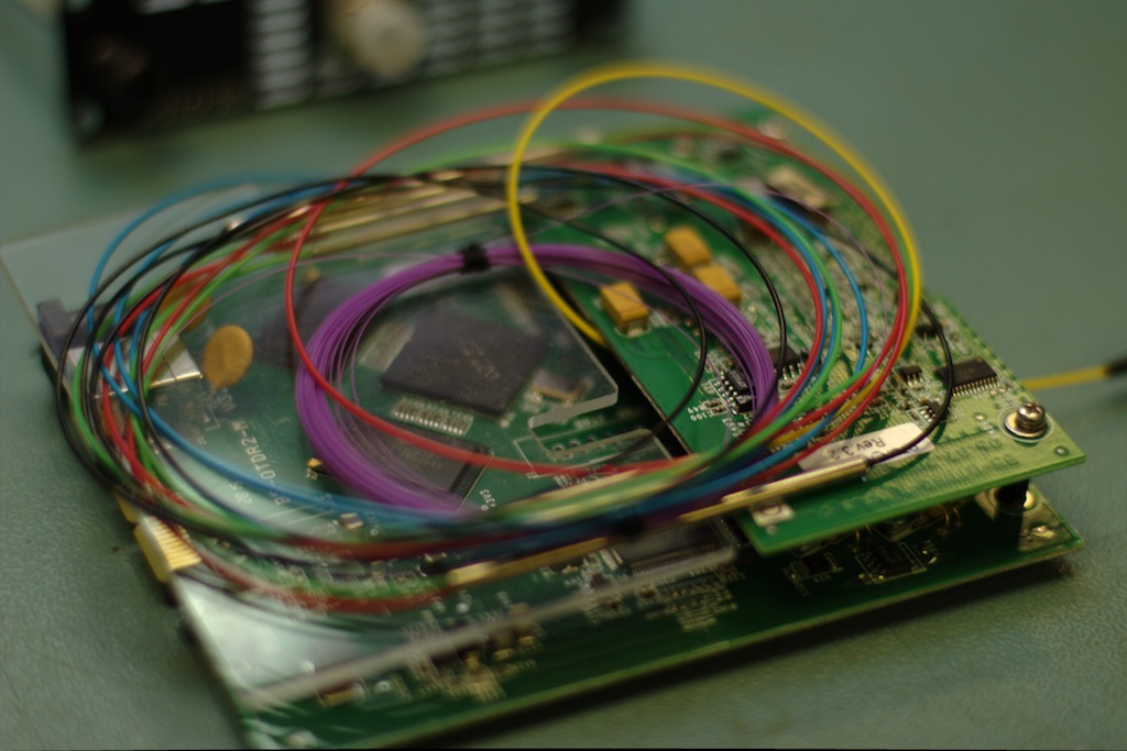
The story of the high threshold of entry, races races and confidence in the future, as well as optics, circuitry and a little about FPGA. At KDPV - what happened, works and is used in production, and below - a story about the process of creating this "miracle of hostile technology."
On one gloomy winter morning of December 2007, marketers of a small electronics company decided it was time to make their own OTDR . To be inexpensive and at least as good as foreign ones with decent features.
No sooner said than done! The project was given a start at the start and research, search for solutions and experiments began. Plans, schedules, studying of the special literature, parameters, features, opportunities and characteristics of similar devices.
Be sure to note that:
- before the OTDR, the team of instructors and programmers was engaged exclusively in digital systems and measurements (the pulse shape in E1 we do not take into account), and the physics of the OTDR is analog;
- the events described took place from 2008 to 2013, that is, quite a long time ago;
- Yes, the process took five years (actually, more).
Introduction
I will try to tell and show on fingers why reflectometers are needed, on what principles they work, and also about the main parameters of these measuring devices.
Today, no one will be surprised by the high transmission rate (although someone and 100 Mbit / s - quickly). For more than a decade, the globe has been entangled with optical cables that drive huge traffic at gigantic speed. 10/40 / 100G in conjunction with DWDM with a potential band of 16 terabits / s in a single fiber as thick as hair - this is what keeps the modern Internet, clouds and other google amazons. OK, not only on this, but fiber optics still remains the main physical transmission medium for such speeds.

The world is imperfect, and the cable at any time can be damaged: chopped, broken, pinched, etc., etc. Well, if it is somewhere nearby and can be seen with the naked eye: for example, you can sometimes find a wild excavator tearing the lion's mouth optics near your data center. And if the gap is under water or underground? Laying a new or old cable to find a fault is not that expensive, but very expensive. The right thing to do is to isolate the problem and weld the torn fiber.
How to find a place of damage, if the length of the route section is tens and hundreds of kilometers, and physically it is impossible to get to every meter of cable? Here an optical reflectometer (OTDR, Optical Time-Domain Reflectometer) comes to the rescue - a device with which you can find the fault location and determine the quality of welding and connecting connectors at a distance of up to ... kilometers and with an accuracy of ... meters / centimeters. Distance and accuracy depend on the characteristics of a particular device. And the price of the device also depends very well.
Disclaimer: of course, rupture is only one of several types of problems arising during the operation of fiber optic lines (fiber-optic communication lines), but I do not aim to tell in detail about all the parameters of optical fibers: there are good books in Russian and English (see in the list of references below), as well as a great article on Habré.
So, the main parameters of optical reflectometers:
- dynamic range (range); eg 36/34 dB
- resolution (accuracy); we could make the resolution less than 4 cm
- dead zone by event (at what minimum distance from each other malfunctions can be detected)
- dead attenuation zone (for measuring losses on connectors and welds)
OTDR working principles
(very primitive, without going into theory)
Let us accept as a fact that the physics of the propagation of light in an optical fiber is such that the beam is reflected both from the cable envelope and from each point of the propagation medium, as well as from all inhomogeneities in its path. Naturally, it is reflected in different ways and in different directions. We will be interested in the reflection in the opposite direction, reflection from inhomogeneities and signal attenuation.

The speed of passage of the beam through the fiber is about one and a half times less than the speed of light in a vacuum. Knowing the speed and measuring the time between the transmission of a pulse into the fiber and the reception of the aposing signal, one can uniquely calculate the distance to the reflection point.
The light signal passing through the fiber loses its power. The attenuation of the power (attenuation) of the light signal depends, among other things, on the wavelength. If you correctly measure the power of pulses reflected from remote points of the fiber and construct a graph, then you can get a trace characteristic - a trace.
Reflectograms
The article mentioned above has many beautiful color graphs with reflectograms, labels and other characteristics, but the meaning of all the pictures is the same - they show the change in power of the reflected light beam with increasing distance from the beginning of the optical cable.

(the distance on the horizontal scale is arbitrary, kilometers should be
more)
On x - distance, on toys - the ratio of the power of the reflected signal to the power transmitted. Okay, for those who are carping, 5 decimal logarithms of this ratio are the same decibels, but five, not ten - because the signal goes a double way - back and forth. The signal decreases exponentially, so a straight line is obtained by logarithmization. By the way, I’ll tell you about logarithm later.
High bursts at the beginning and at the end of the graph - the reflected signal from the beginning and from the end at the air / fiber interface.
Measurements are usually carried out for two wavelengths - 1310 and 1550 nanometers. For measurements in PON / FTTH, a signal with a wavelength of 1625 nm is used. The attenuation coefficient for different wavelengths is different, it can be seen on the trace and can be determined by the angle of inclination of the straight (as it were) sections of the graph. Naturally, for different cable manufacturers, the attenuation coefficient is also different, and the smaller it is, the better, but the order is very similar: approximately 0.19 dB per 1 km for a wave of 1550 nm and 0.33 dB / km for 1310 nm. The figure shows two reflectograms for the same cable, made at different wavelengths:

(the distance on the horizontal scale is conditional, kilometers should be more)
Thus, if the long fiber is laid without welding, strong bends and joints, the optical signal power will decrease by the attenuation coefficient every kilometer and after 100 km the signal will be no less than 2000 ... times (100 km * (-0.33dB) -33 dB) is weaker than the transmitting LED emits.
Since the reflectometer is used from one end of the cable, they measure the reflected signal, which will be weakened by another 33 dB on the way back, and this means that the power of the returned beam, which has traveled 200 km (one hundred and one hundred and there) will decrease almost 4 million times : there is 33 dB less, back another 33 db less, total 66 dB (1 / (10 ^ -6.6) = 3'987'071.7).
The idea is that the signal at the input of the OTDR receiver varies in a large range: from tens of milliwatts to fractions of nanoWatts. And on current - from tens of milliamps to picoamper.
In practice, at least the losses at the connector and at the internal splitters are added to the signal attenuation coefficient. That is, when designing, it is necessary to provide for a larger range of signal changes. By the way, for reflectometers there are concepts of nominal working and nominal dynamic range. Worker, as you can guess, is less.
Knowing the attenuation in the cable and the dynamic range of the device on the passport, you can understand what distance the reflectometer can measure. With a conventional trunk reflectometer, this is 36/34 dB. Calculate the distance:
36 dB / 0.33 dB / km = 109 km for a wavelength of 1310 nm
and
34 dB / 0.19 dB / km = 178 km for a wavelength of 1550 nm
(OTDR users will correct me again, which is actually less)
As a measuring signal, pulses of a given length (from 3 nanoseconds to 20 microseconds) are used. On short tracks, measurements are made using short pulses, on long, respectively, long ones. The longer the pulse, the greater its power and the further it will be possible to see its reflection from cable inhomogeneities and the longer the track can be “shot through”.
We use short pulses - we obtain high resolution, long - long range. Actually, this is somewhat simplistic, but I hope it allows you to understand the common problems and difficulties encountered by the OTDR operators in the process of choosing parameters: a compromise is needed between resolution, range, and measurement duration.
A longer pulse is more power and a very long path can be measured. By the way, an infinitely long impulse cannot be made, since you need to measure the reflected signal, and for this the radiation source must be turned off. Yes, and emitters are designed for pulsed operation with a specific duty cycle. If you reduce the period between pulses or shine for a very long time, then you can easily burn the laser diode, and this is at least expensive and harmful to the environment.
(Pulse length is the time during which the laser LED is shining. The period is the time between pulses when the LED is off. We installed a diode from the dvd drive in the zero version of the transmitter, sealed the blue tape with a lens and after switching on the tape, with smoke and hiss burned through.)
Development process
It so happened that at first one team developed the OTDR for four years, in the fourth year, in parallel and urgently, they started creating an alternative version, and in this article there is a story about the adventures of the second team. I will also tell you a little about the first option, but then.
Task setting: to make an electronic device - an optical reflectometer with a dynamic range of 35/37 decibels (and not 34/36, so that it is larger than that of competitors) and a dead zone for an event - no more than 1 meter.
After a preliminary analysis and calculations, it was concluded that the main
system components will be as follows:
- the source of light pulses is a laser LED (two pieces, one for 1310, the other for 1550 nm);
- receiver - avalanche photodiode;
- an amplifier with a large dynamic range (see "calculations" above);
- analog-to-digital converter to be sold to Russia, because speed acts on the embargo;
- FPGA for summing and averaging samples;
- control system (microcontroller in the measuring part and embedded linux in the interface);
- graphical user interface;
- and so forth
And so on. This is a set of splitters, KZDS (a set of parts for splice protection), a compensator fiber of a dead zone, an FC connector for connecting to the measured track. About the power and cooling systems, too, do not forget.
Some more source data
Transmitter: we need more power - we put a powerful emitter in the circuit. At the same time, it must be both powerful and fast in order to work on short pulses, but not to such an extent that it is possible to set fire to matches with a laser beam or to melt the fiber. Calculations by calculations, but in the end they came to the conclusion that there are not so many emitters on the market and decided to install with the same parameters as other manufacturers of devices. The length and period of the pulses will be controlled from the FPGA.
Optical part: two emitters and splitters 50/50, external connector - FC.
The receiving part: large dynamic range - you need an appropriate amplifier, and the corresponding ADC.
Computational part: noise will always be present in the measured path (thermal noise in the fiber, internal noise of the device components, pickup, etc.). You can get rid of noise in the traditional way - by averaging: we sum N identical measurements and divide by N. We will average the values obtained from the ADC in FPGA, store it in external RAM.
We try to use ready-made components to the maximum. For example, an amplifier with variable gains. However, this device was not useful to us.
Block diagram
Block diagram times (incorrect). Logarithmic
In general, something like this: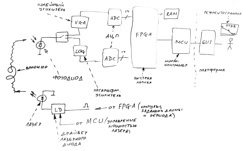
For simplicity, the figure shows only one emitting diode. In a real device, there are two (1310 and 1550 nm, power 50 and 40 mW) or even three (1625 nm). Splitter, introducing attenuation of 3 dB, is also not in this picture.
Avalanche photodiode - NR8300FP-CC - with a typical multiplication factor of M = 40 (300 euros per piece). Why avalanche photodiode and why you can not do the usual? Because the reflected signal that has traveled a long distance is so weak that an ordinary pin-photodiode simply will not generate a current and will not digitize anything. And the avalanche photodiode can additionally amplify the received signal, the picture shows the dependence of the avalanche diode multiplication factor on the reverse voltage and temperature:

Even in this version of the receiver there are two amplification channels operating in parallel. One with a wide bandwidth (600MHz), the other with a large dynamic range (100 dB-range 10nA-1mA).
As well as the ADC (analog-to-digital converter) - a two-channel, 14-bit, 65 MSPS (mega-samples per second), from which the digitized data is sent to the FPGA (FPGA), where averaging is performed, and then - to the upper level, control processor.
In addition, as already mentioned, the FPGA controls the duration of the pulses generated by the laser diode.
First start
Hooray! The scheme was drawn, the board was thinned, mounted, wrote test firmware for FPGA, scripts controlling the device and started testing.
The transmitter was tested separately, the receiver - along with the transmitter ...
… To be continued
Continued - in the next article, after about a week. And so it happened a lot. In the following chapters I will tell about:
- the problem of "linearization" of graphs obtained when working with a logarithmic amplifier,
- using the Peltier element to stabilize the temperature,
- errors in the design of connectors between the receiving and transmitting parts of the device,
- search for the optimal reverse bias point of the avalanche photodiode,
- fighting saturation amps
- dead zone compensator, meter calibration and fiber cassette,
- I will lay out working and non-working concepts and trace data for octave and matlab,
but with pleasure I will try to answer the questions.
Thank you for reading the first part of the story to the end!
Links
- https://habr.com/post/227647/ - article about the analysis of reflectograms when welding optical fibers
- https://github.com/sid5432/pubOTDR/wiki/The-OTDR-(Optical-Time-Domain-Reflectometer)-Data-Format - reverse engineering of SOR files (common format for storing reflectograms)
- http://ntc.metrotek.ru/b45otdr.html - page of the measuring device for which the reflectometer module was developed
- https://www.digikey.fi/product-detail/en/cel/NR8300FP-CC-AZ/NR8300FP-CC-AZ-ND/1968838 - avalanche photodiode too expensive
- https://www.digikey.com/products/en?keywords=ad9248bstz-65 - used in the first variant of the scheme a logarithmic amplifier with a large dynamic range
')
Source: https://habr.com/ru/post/358648/
All Articles