FPP via FPL: Accelerate FPGA download
Hello!
Recently there was a task - to speed up the loading of FPGA. From the appearance of power to the working state, we have no more than 100 ms. Since the chip is not the newest (Altera Cyclone IV GX), it is simply impossible to connect a fast EPCQ flash drive to it. And we decided to use FPP (Fast Passive Parallel) mode, having installed CPLD Intel MAXV outside with FPL (Flash Parallel Loader) outside. When starting, CPLD loads data from a flash drive and generates FPP signals at its outputs.
However, before you make your plans, we collected a DIY layout from what was at hand, and began to experiment "on cats". Unfortunately, because of the snot on the board, the operating frequencies had to be reduced, but the essence of the FPP operation did not change, but the debugging was simplified. I decided to write about what happened and how the FPGA is configured in this article. Who cares, welcome under cat.
What I plan to talk about:
- FPGA configuration brief. Typical timeline, what are the modes
- What steps does the FPGA load time consist of?
- what is FPP
- about FPL, what is its role
- about EPCQ and FPL support
- about the results of experiments with pictures
How is FPGA configured?
There are two types of FPGA boot - active and passive. Active means that the FPGA clocks the external flash and reads the firmware from there. Passive - that there is a certain host (processor, FPGA, controller) that loads the FPGA firmware.
Active is well known to everyone, probably: we connect the EPCS / EPCQ flash drive, upload firmware via JTAG and enjoy life, since all the rest of the work of reading data for us will be done by FPGA when the power is turned on.
Passive is a bit more dreary, because it requires the implementation of additional logic: the processor must load the firmware from somewhere, someone has to “put” this firmware in it, etc. But passive mode is often faster. For example, Cyclone IV supports DCLK 40 MHz and 1 data bit in Active Serial mode and 100 MHz and 8 data bits in FPP (Fast Passive Parallel) mode, which is 20 times faster.
The main signals that are responsible for configuring FPGAs are nCONFIG, nSTATUS, CONF_DONE:
- The nCONFIG input allows you to reset the FPGA (difference from 1 to 0) and initiate the firmware download (difference from 0 to 1)
- The nSTATUS output tells you whether the FPGA is ready to receive data (level 1) and whether some error has occurred during the configuration or operation of the FPGA (drop to zero)
- The CONF_DONE output makes it clear that the FPGA is configured. To be precise, the FPGA received all the configuration data.
The timing diagram in these modes is not much different. Here is a model for our case - passive parallel :
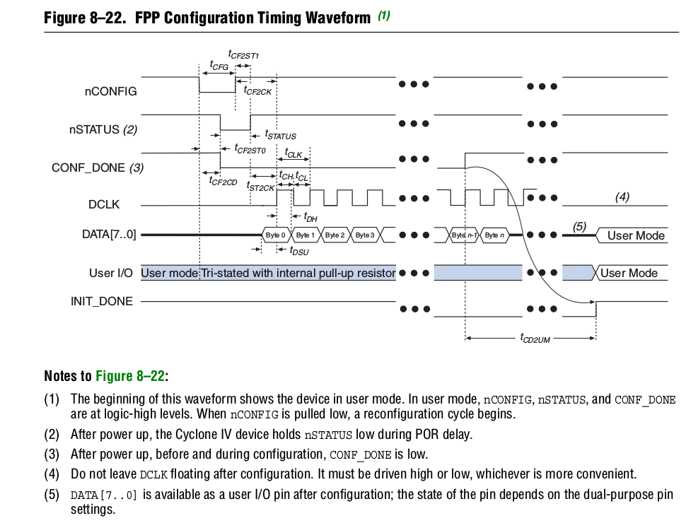
The following happens in it:
- external host resets FPGA (nCONFIG: 1 -> 0)
- The FPGA confirms that it is ready by first setting nSTATUS to zero and then releasing it to 1. Also, the CONF_DONE signal is reset to 0
- external host initiates FPGA configuration (nCONFIG: 0 -> 1)
- external host writes data (firmware) until the CONF_DONE signal appears (after CONF_DONE, a couple of dummy ticks are needed)
Read more about configuring here .
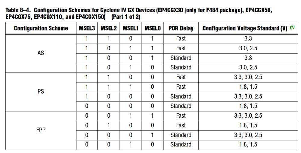
The choice of configuration mode is made by special FPGA - MSEL legs. In different families, the number of modes is different. For example, in Cyclone V, the compression mode and the firmware encryption mode are selected in addition to Active / Passive. And in Cyclone IV - only Active / Passive and POR Fast / Standard
How does FPP work
FPP (Fast Passive Serial) is a passive mode in which the configuration is loaded into the FPGA with words (1 byte or more) and synchronously, according to the clock cycles of the DCLK signal.
The “light version” of this mode is Passive Serial, where the firmware is loaded bit by bit.
For this mode, Dedicated pins are used, some of which (most significant bits of the data) subsequently become normal I / O:
- DCLK
- DATA [7: 0]
In higher-end chips (Stratix V, for example), you can load the firmware at 2 (FPPx16) and 4 (FPPx32) bytes per clock.
FPGA load time
Let's calculate the FPGA boot time in passive mode. The beginning will be considered the appearance of voltage on the chip (when it reaches a certain value), and the end is the appearance of the CONF_DONE signal.
The time enlarges from the following stages:
- tPOR: power on reset. In Fast mode, it takes a few milliseconds, and in Standard mode, hundreds of milliseconds (!). However, Fast imposes more stringent requirements on the power supply system, since more energy is spent at the start.
- Configuration Handshake: host waits for nSTATUS = 1, resets FPGA (nCONFIG: 1-> 0), initiates (nCONFIG: 0-> 1). This stage takes fractions of a millisecond and can be safely neglected.
- tCFG: sending data to FPGA and monitoring CONF_DONE. This part takes the main time, which is proportional to the size of the firmware and inversely proportional to the frequency of the DCLK at which data is recorded.
- tINIT: chip initialization with data loaded into it. After this stage is completed, the FPGA is fully operational (located in USER MODE). Takes less than a millisecond, so we also neglect
tPOR depends exclusively on MSEL settings. Naturally, where the load time is fundamentally and the power scheme allows, you need to set the mode to Fast (see the tables with MSEL above).
With tCFG, everything is a bit trickier, because it depends on:
- DCLK frequency. It is determined by the capabilities of the FPGA and external host. For cyclone IV, Fmax is 100 MHz
- firmware size. It is determined by the FPGA family and the number of logical cells in a particular chip. In each family, there is always a table with the maximum firmware size for each chip. For example, for Cyclone IV, see here: link
- firmware compression In some chips (Cyclone V) it is determined by the MSEL settings, in some (Cyclone IV) - only by the settings of the firmware converter. Typical profit from compression is 50-70%, but no one undertakes to give 100% guarantee that it will be in your design that way. Therefore, it is risky to “pledge” this number.
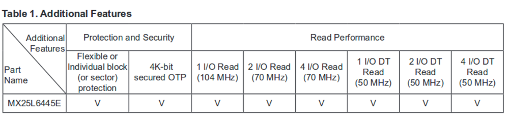
This is what the firmware size documentation for Cyclone IV, Table 8-2 , says:
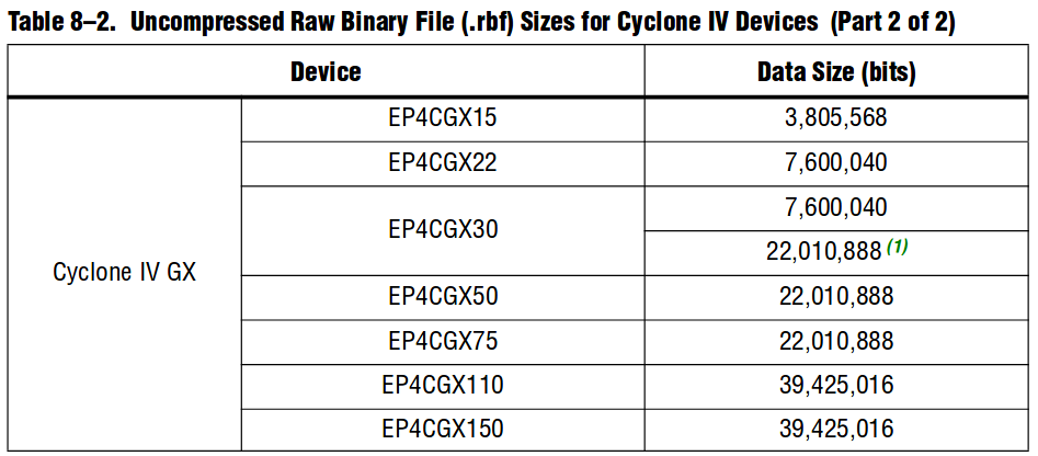
For example, for the EP4CGX75 chip, the maximum firmware size without compression is 22.010.888 bits = 2.751.361 bytes. If we assume that the external host is ready to operate at a frequency of 100 MHz, then it will take 2.7e6 / 100e6 = 0.027 seconds = 27 milliseconds to load the maximum firmware. And if you use compression, then this time can be reduced by about half, getting less than 15 ms!
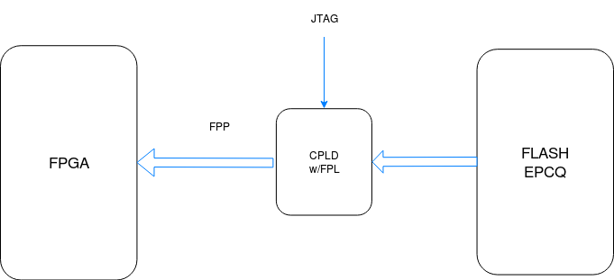
However, to obtain a DCLK = 100 MHz frequency, you need to be able to read the firmware at least at the same frequency. One of the options offered by Intel / Altera is to use CPLD MAX II / V for this purpose. On the one hand, CPLD reads Flash, on the other hand, it writes to FPGA.
FPL
And for this task in the collection of ready-made IP-cores there is a Flash Parallel Loader . This core supports a set of Flash chips with different interfaces (QSPI, NxQSPI, CFI, etc ...), allowing you not only to read the firmware from them, but also to write it down by connecting via JTAG.
It also allows you to write to Flash not one firmware, but several, thus organizing a "rollback" to a stable image in case of problems with the update.
See datasheet for more details.
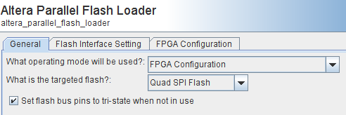
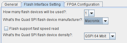
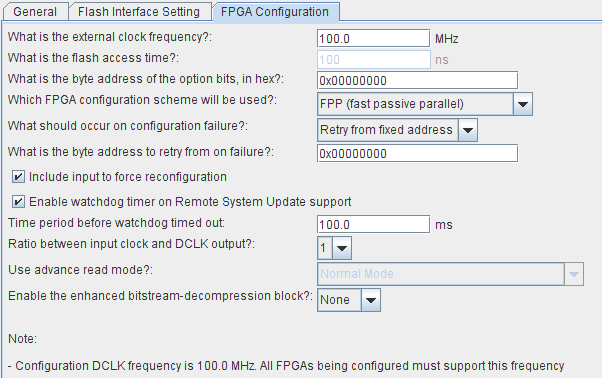
We chose the Flash Programming & FPGA Configuration mode and the EPCQ as the Flash. This allows us to meet the required download time and at the same time have the ability to flash Flash via JTAG or flash EPCQ using another host.
Screenshots of the settings we used:
CPLD firmware occupies 1267 LE and is almost 100% occupied by EPM1270F256C5 (MAX II) or 5M1270ZT144C5 (MAX V). Without the flash firmware option (say, if some other host can do this), the resources used are significantly less and a margin of 754 LE appears.
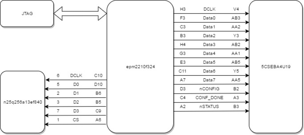
Here is the CPLD inclusion scheme:
How does FPL work (approximate algorithm):
- on the ready signal (nSTATUS = 1) from the FPGA, it activates nCONFIG according to the diagram above
- when the FPGA is ready to receive data (nSTATUS has made a drop to zero and back to one), the FPL reads the service data block from Flash. This block contains the addresses of the firmware (or firmware, if there are several)
- The FPL starts downloading the firmware that the input port fpga_pgm [2: 0] is pointing it to. We used two firmware, so this port was served on 1
- If an error occurred during the download (this may be, if the image is not completely flooded, “broken” or for another chip / family), then the FPL “switches” to the factory default firmware, which by default is considered to be zero
- FPL loads a zero image into FPGA. If everything is not OK with him, then he makes several more attempts and stops
Let's see what kind of performance we can “squeeze” out of the described configuration with one EPCQ. For this you need a little idea how the EPCQ works.
How EPCQ works
EPCQ (advanced version of EPCS) is NOR-flash, which has a SPI interface for most commands and for some commands - QuadSPI. It is read very quickly, and it is written and erased very slowly.
Commands (erase, read, write) always arrive in flash using normal SPI, and then the behavior of the flash drive depends on the command. For example:
- if we write the READ / FAST_READ command, the read will be performed in single-bit mode
- if FASTDTRD, then in single-bit mode with DDR
- if 4READ, then in four-bit mode
- etc.
See, for example, a description of flash macronix
Maximum EPCQ read performance is achieved using all four bits at maximum frequency with DDR. However, the temporal characteristics vary nonlinearly:
That is, throughput will be in the cases given in the example above as follows:
- READ - 104 Mbps
- FASTDTRD - 100 Mbps
- 4READ - 280 Mbps
- 4DTREAD - 400 Mbps
There are flash drives and more brightly, for example S25FL064L , in them the frequency does not fall with an increase in the reading capacity. Therefore, for "squeezing maximum speed" it is better to focus on them.
If you recalculate 4READ / 4DTREAD modes during the time required to read our firmware for Cyclone IV, you get 78 ms / 55 ms. Let me remind you that in order to "catch up" with FPP, you need to meet 27 milliseconds (see above).
It turns out that the bottleneck in our task is the interface for reading the firmware, and not the FPP itself. And if it was required to get not 100 ms, but significantly less, then we would have to use two EPCQ flash drives. But for our case, the normal 4READ is enough.
A list of supported EPCQs is provided in the PFL documentation, section 1.2.1 .
It is curious that Intel / Altera not so long ago refused to release their EPCQ and now officially support Micron's instead of their own .
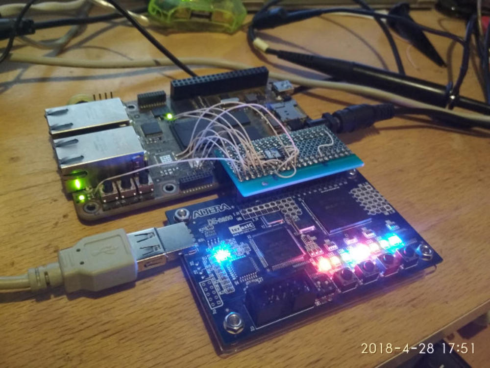
It's DIY time!
In order to combine theory with practice, we took into our hands what was:
- kit Ethond c Cyclone V SoC (5CSEBA4U19C8SN)
- ancient kit from Terasic c MAXII EPM2210f324 on board
- EPCQ Micron N25Q256A13EF840
- soldering iron, wires, "dandy"
- man with golden hands, solder and flux
The chips hooked up as follows:
On a blind mount, a QSPI flash drive was soldered and mounted into a layout:
After completing a small quest (see Doc, section 1.4.1 ) to create the firmware that is used for uploading to EPCS via PFL (link), we took the measure of “time”. When creating the firmware, please note that you need to specify CFI-flash as a target, even if EPCQ is used.
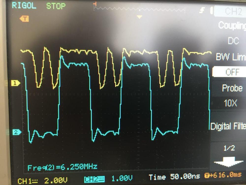
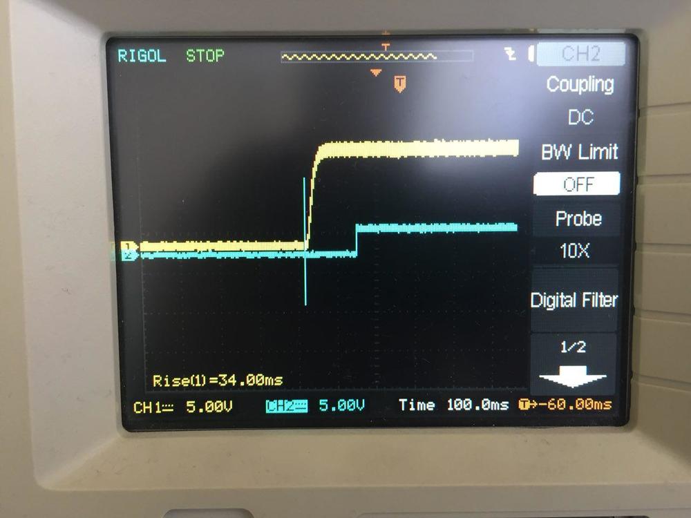
Alas, because of the mounted installation and the "beard", the operating frequency of the FPL turned out to be 6.25 MHz, and the EPCS takes 25 MHz. We adjusted this clock using the "Ratio between input clock and DCLK" option by setting the value to 8 (input clock = 50 MHz). Here is the plot of the FPP (blue) and EPCQ (yellow) clots: it is clear that for each FPP clock cycle there are two EPCQ DCLK cycles, because the FPP bit width is twice as high as the EPCQ (8 vs. 4).
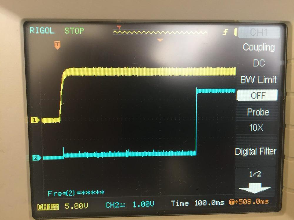
Here is a diagram of the supply voltage (yellow) and the CONF_DONE signal (blue) in the Standard POR mode and without compression: you can see that the total load time is 780 ms.
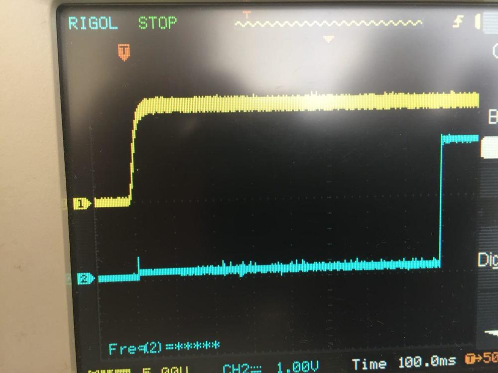
There is about 100 ms between the appearance of power and the nSTATUS signal, signaling the chip is ready to accept configuration data:
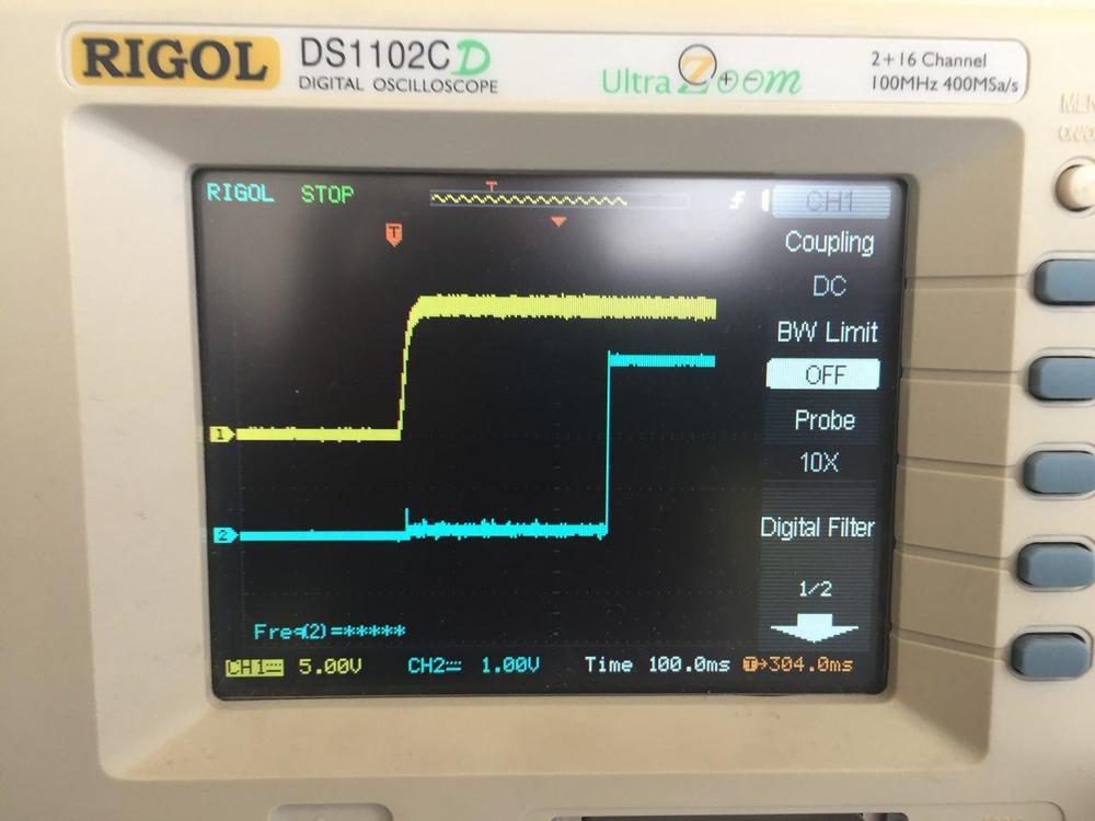
And if you enable the Fast mode (we change just MSEL, see the table above), then the POR occurs in a matter of milliseconds and the download already takes ~ 680 ms:
And the last step - turn on compression. To do this, tick Quartus when adding a firmware file to PFL and switch MSEL (you don’t need to touch MSEL in Cyclone IV). And we get a completely different picture:
Compared with the original version without compression and Fast POR, we have a twofold gain of about 400 ms.
Combining theory with practice
Let's calculate whether the measurements made with the oscilloscope agree with the calculations. Time tPOR is considered equal to zero, because use Fast POR. Therefore, we can only calculate how much the load time of ~ 680 ms converges with the size of the firmware and the FPP DCLK frequency.
The size of our Cyclone V firmware is ~ 4 megabytes (32 megabytes). The clock frequency of the FPP DCLK is 6.25 MHz. Per clock is transmitted 8 bits, that is, 1 byte. Therefore, the estimated time is 4 / 6.25 = 0.64 seconds. Woo-la!
If we proportionally increase the FPP DCLK frequency, for example, 8 times - up to 50 MHz, then we will get a time of 80 ms. And if we also include compression, it is even less.
findings
Theoretically, the FPGA can load in tens of milliseconds, according to our calculations for Cyclone IV - in about 30 ms. However, it must be borne in mind that for this, a host that loads data into FPGA, like Flash, from which data is loaded, must match the bandwidth.
In the more recent FPGA chips, the EPCQ flash drive can be connected directly and use active mode, and if the design does not allow switching to a new family, then you can install an external loader and use passive mode. For this, we use the Flash Parallel Loader, which we used in our layout.
With the described approach with FPL and one EPCQ, it is quite realistic to bring the FPGA load time to 50 ms.
Anyone who read to the end can put a monument thank you very much!
')
Source: https://habr.com/ru/post/358638/
All Articles