History of one oscilloscope on stm32
Just over a year ago, I had the idea that it would be good to make an oscilloscope. Then I wanted it to be an independent device with its own TFT display, and indeed, the idea of dealing with TFT displays seemed very promising to me. After some time, a 3.2-inch TFT with a SSD1289 driver was ordered for Ali.
At that time, I already had the experience of programming AVR microcontrollers , so I decided to launch the display on my favorite Atmega16. Whether it came to creating an oscilloscope then did not yet know, but I knew for sure that I would use TFT in my projects, so I did not search for third-party libraries, but decided to write my own, which I use to this day.
After it was possible to initialize the display, it became clear that an oscilloscope could not be made on the Atmega16. It is very slow for a display of this size. And something inside told me that it was time to switch to the STM32, but it also stopped me. In general, the deliberation process was short and a board with STM32F103VET6 was ordered on Ali. But besides the reason described above, there was another reason to switch to STM32 - the built-in 12-bit ADC at 1Msps, which can be used to digitize the signal.
')
To my surprise, after several weeks of working with STM32, it became clear that there was nothing difficult in them and I stopped understanding why I did not switch to them earlier. It was not difficult to transfer the code written for AVR to STM32, but the thought that I needed the display to work at maximum speed did not give rest, and for that I had to deal with the FSMC . In fact, everything turned out to be simple here - it took me one weekend. At this preparatory events with the display were completed and it was possible to go directly to the implementation of the oscilloscope.
The primary task was to learn how to display a signal on the display, for this purpose I accumulated the required number of ADC samples, then displayed them on the screen, filled the screen with black color and so on in a circle. By the way, even then, DMA was used to save data to the buffer.
The first step was taken and I was overwhelmed with joy and pride for the work done. Further, I wanted the sinusoid not to run, but to stand, for this it was necessary to learn how to start the conversion of the ADC by trigger.
This can be done using a conventional comparator, as shown in the diagram below.
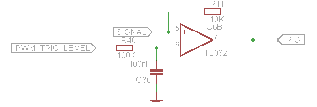
Comparator at the shelter.
A reference voltage is applied to the inverting input, which is formed using PWM and RC chains. A direct input signal is the same that is fed to the input of the ADC.
When the voltage at the direct input becomes higher or lower than the voltage at the inverted input, the polarity at the output of the OU changes. This change fixes the output of the MC configured for external interrupt. By changing the active front, for an external interruption, you can capture both on the rising and on the falling edge.
Further, DMA is enabled in the interrupt and works until the buffer is full. Yes, it is DMA, ADC always works in my implementation. The feedback resistor is needed to increase the rate of rise, and the OS itself for this business, it is advisable to choose quickly.
After some time, I came across a review of DSO 138 and from the same review I learned that its scheme is available on the Internet and decided to borrow a piece from there.
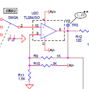
Fragment of the DSO scheme 138.
What makes this piece of circuit?
The voltage range with which the ADC can operate determines the reference voltage levels ( + VREF and -VREF ), they should not go beyond the power supply range of the microcontroller. The lower limit of the range is limited to 0 volts, the upper - 3.3 volts. From here it becomes clear that measuring the negative voltages of the ADC cannot, and this is necessary.
In order for the ADC to sense negative voltages, it is necessary that, in the absence of a signal, half of the reference voltage in our case is fed to 1.6 volts. In this case, when measuring a negative voltage, for example, minus 0.3 volts, the voltage at the ADC input decreases by 0.3 volts and becomes equal to 1.6 - 0.3 = 1.3 volts. This voltage ADC easily digitized. This example is approximate because it does not take into account the gain of the circuit (in this case, we took it for 1), but it is clear.
I would also like to note that the power supply of the op amp is bipolar, this is necessary in order for the op amp to work with negative voltage. If the op amp power is unipolar (0 is fed to one power pin, 5 volts to the second) and a negative voltage is applied to the input, the op amp will not feel it and cannot do anything with it, that's it.
For the implementation of bipolar power, I used two charges from the phone, connecting plus one with minus to the other, and took the potential of this connection as a reference point, that is, the ground.
The scheme was assembled on a breadboard and now the oscilloscope could capture by trigger and measure negative voltages, I had no idea what to do next in terms of hardware, so I switched to software.
At that time, I already had a clear understanding that the buffer should be circular, and the size borrowed from the DSO 138, that is, 4096 points.
Why so many points?
Such a number of points using thinning allows you to implement some scans that can not be implemented in hardware. For STM32, the conversion duration is 12.5 cycles, in order to find the sampling period, add a value to the conversion duration, which is determined by the SMPx bit field [2: 0]. At the moment, the DSO 138 reduced the buffer size to 1024 points, I have 4096 left.
So what is the ring buffer for?
The ring buffer is necessary to change the ratio of the number of pre and post samples on fast sweeps. Prefetches - samples before trigger trigger, postfetches - samples after trigger trigger. The algorithm of operation is as follows, after the oscillogram is drawn:
- we accumulate the necessary quantity of pre-election;
- allow external interrupts;
- MK starts to perform some third-party tasks, until, until the external interrupt signal comes.
On this signal, the buffer is supplemented with post-samples and the entire waveform is displayed.
The user can set the number of pre-selections only on fast sweeps; on slow ones immediately after capturing, points are drawn on the screen, bypassing the buffer. In fact, of course, there is a buffer, because from the time it became clear that to paint the workspace after each drawing is unreasonable, you can simply draw the same waveform only in black and restore the markup, thus reducing the time of drawing one waveform and disappears, such an unpleasant effect like flicker.
The result can be seen on video.
What could the prototype of the oscilloscope at that time? (And what he could something?)
It was possible to change the sweep time, select the trigger type, select the active front, change the number of pre and post samples, change the trigger level, also change the base level.
As for the type of trigger, in the auto mode, everything happens just like in the norm mode, except that if the signal causing an external interrupt does not come within 100 milliseconds, then a timer interrupt occurs and the buffer is filled in it.
In order to implement the remaining functions, I had to return to the hardware again. And I think many have a question, why not zayuzat the entire scheme from DSO138?
Quite simply, I wanted the position of the attenuator to be switched by electronics, not by switches and, most importantly, when the open input was changed to the closed one and vice versa, the relay would click))
In general, I was faced with the task of finding the analog part that would meet my requirements. In fact, this is not an easy task, if it were not for one thing ...
At one point, I remembered that I had an oscilloscope, and its developer answered me questions on skype about a year ago, in general, I decided to write to him.
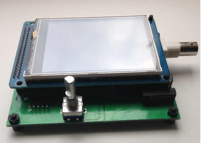
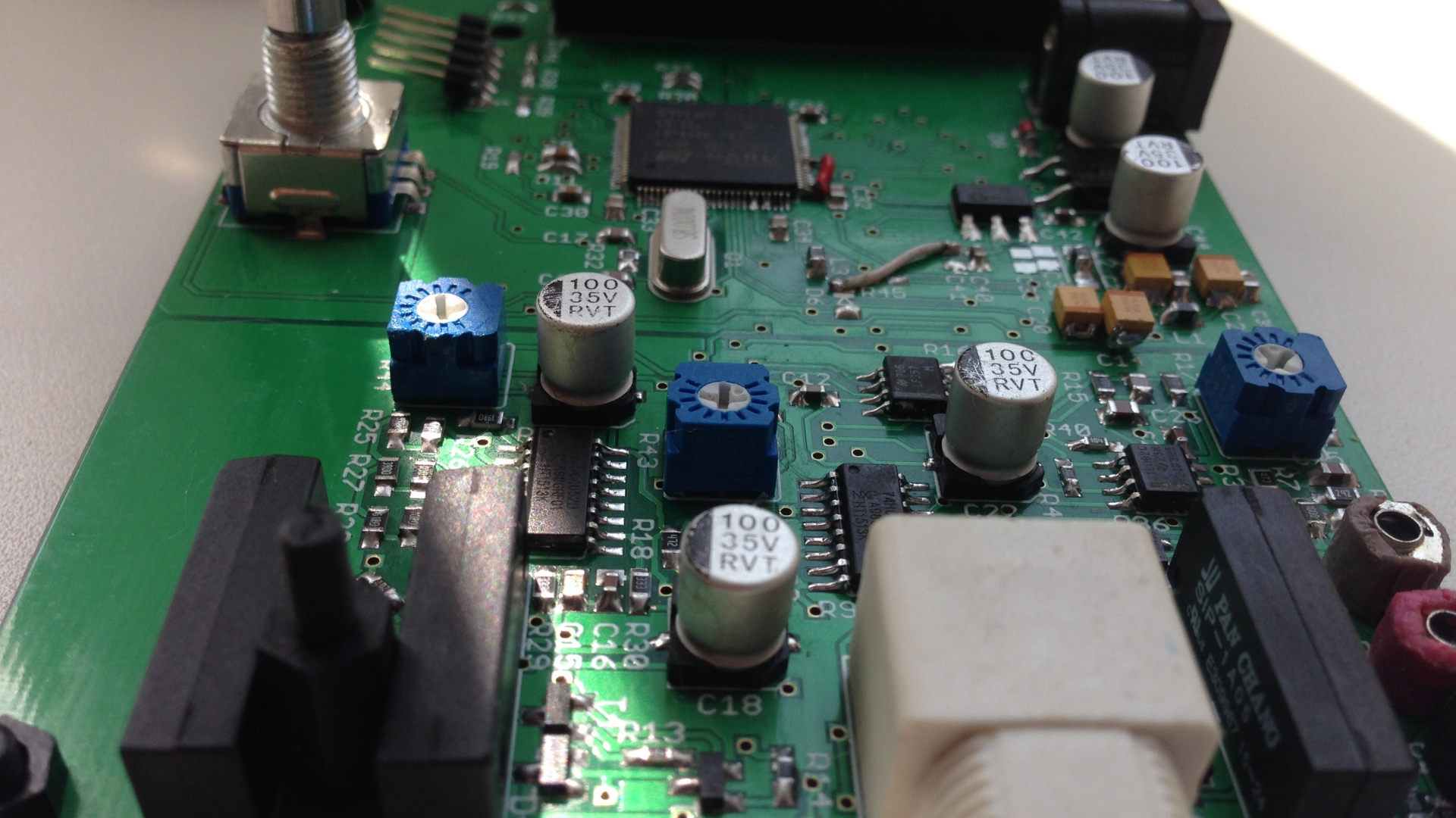
After I told him about my plans to make an oscilloscope, he offered me several options for the analog part, I chose the most comprehensible scheme for me, asked him my questions and set about implementing it. A few months later the oscilloscope was ready.
The result was an oscilloscope with the following characteristics:
Power supply: 9 V
Current consumption: 110 mA
Sampling Frequency: 1 MSa / s
Analog Bandwidth: 0 - 200 kHz
Vertical resolution: 12 bits
Maximum input voltage: 50 V
Vertical sensitivity: 10 mV / div - 10 V / div
Horizontal scan time: 10 µs / div to 200 ms / div
Input Impedance: 1 MΩ / 20 pF
Input Modes: DC, AC, Ground
Start Modes - Sweep: Auto, Normal, Single
The result can be seen on video.
Source: https://habr.com/ru/post/358330/
All Articles