Implementation of the program code for the display module on ILI9341 + STM32. Part 4.2
Part 1
Part 2
Part 3
Part 4.1
Opinions were different about the analysis of the code and its necessity in general. In this article I tried to implement the “golden section” method, therefore:
a) at the end of the article the source code will be attached to theexperts not to read further
b) I will give the algorithm of work and analyze it
c) explain how to use SPL libraries
d) in the volume of the article I will tell you how to use a certain periphery, I will show the implementation of working with it in the code
e) I will describe in a separate paragraph work with ILI9341, since the topic is quite chewed up, then I’ll just tell you about the main thing - how to think about implementing the initialization function (on the Internet I saw only a code with the phrase: “here’s the initialization, copy and don’t think about it”) and run it through hardware SPI.
Too detailed analysis of the code you will not see here, everything will be in moderation, otherwise I will have to write a book of pages in 200-250. Therefore, study datasheets and other documentation ( links will be ) before you start writing a program. Those who sit for the first time in the MK - do not be afraid if I have any questions, I will tell you and help, so you will master this code.
I will say right away - the code in this article is not “native”, but it has been tested and it works! Since IAR is not the most convenient software for newbies, and somehow many people bypass it because of too much functionality or even some other reasons, it was decided for the educational article to move the project to “coconut” ( CooCoxIDE 1.7.7 ). I also decided to move away from the registers and write the code in SPL.
')
SPL - is the standard library from ST to work with the periphery of the MK STM32. Now the replacement came new libraries HAL, but so far they have not supplanted the first in many projects. You can deduct advantages and advantages in Google.
I chose SPL - because I like the final code more after the “hard optimization”, they are more intuitive, HAL is more adapted to work with various RTOS. This is purely my opinion, I do not ask anyone to take it on faith and tell in the comments that it is better or worse, not worth it.
As I wrote above - there was a transition from registers to libraries, what is the difference:
b) the speed of writing the code is much higher, it took me 1.5 hours to write the code from scratch for the existing algorithm and debug it;
c) easier moving from stone to stone, well, suddenly you do not have STM32F103RBT6, but there is STM32F105VCT6 and you will be collecting on it.
b) in datasheets, all parsing is done on registers and this is the main disadvantage.
To begin, let's figure out thehell to the nose of the overall functional structure of the device:
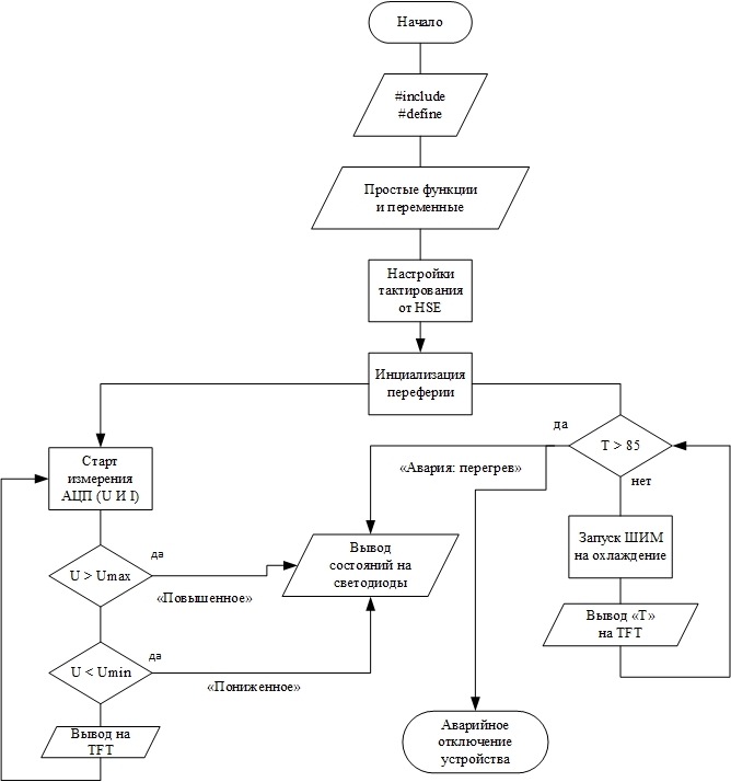
Figure 1 - Flowchart for the control program
Now we can see what our part of the device should measure and how to deal with the data obtained. All measured voltages and currents should be output to the TFT panel, whether the voltage falls within the normal range ( according to GOST ), and at the end multiply the output current with the output voltage and obtain the power consumption of the load. It seems that everything is simple and clear.
Also, our board should measure the temperature, display it on the screen, in case of emergency, 85 o C should turn off the device by filing a log. 1 on the feet of the SD driver IR2110 in the power boards. As well as according to the results of the measured temperature, the value of the duty ratio of the PWM controlling the coolers should be regulated.
All alarm conditions should also be displayed on the LED display, which is used to display"serious things" system problems or device failure.
The functionality of this unit is not complicated, and therefore it will not be difficult to implement it.
1) Download the software with which we will work. This will be CooCoxIDE 1.7.7 , below I have attached a reference to my poison, where you can download the folder with this version of the program, already with SPL installed in it, as well as with the already downloaded compiler so that you don’t suffer and do not search. Everything to start work there is:
CooCoxIDE 1.7.7
2) Download the holy manuscript called datashit on STM32F103 :
Datasheet STM32F103
3) Download at least a scripture called reference manual, which is Googleed as RM0008 and has an epic volume of 1128 pages. This is the most extensive scientific writing that I have mastered, although there were still all volumes of Landau-Livshits, but there are several books all the same ... I’m for something - I advise you to refer to this file with any misunderstandings and curiosities.
RM0008
4) Another very strongly I advise the blog of one boy with a level of knowledge of ST - God, he has there chewed a periphery for beginners and quite complex and interesting tasks:
Nikolay Gorbunov
5) And the last ... run to download a very useful program STM32CubeMX - Official site ST
I hope you downloaded everything that I advised you and now you can start writing the program.
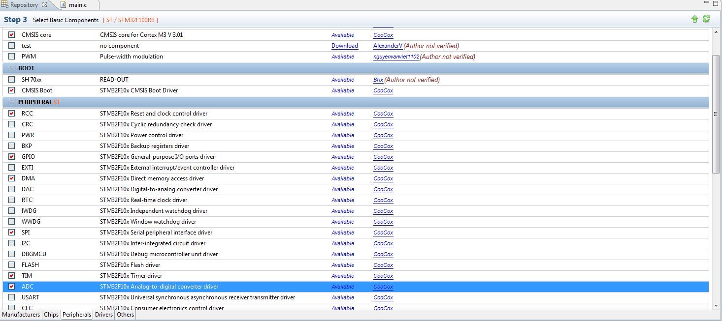
Figure 2 - A repository for selecting the periphery that we will use
Now briefly who and for what answers:
a) CMSIS core - first of all we tick on this library, several more libraries will be connected immediately. This is the minimum you can work with. This library, as its name implies, connects the “core”, the basic functions through which the rest of the peripherals will work
b) The RCC is the library responsible for the clocking of the microcontroller, this is a separate tricky moment that I will consider today. This library allows you to select the source of generation, as well as set the frequency division factor for each periphery.
c) GPIO - library of work with input / output ports. It also allows you to carry out all the initial settings for the rest of the periphery.
d) DMA - this library allows you to work with direct memory access. This can be read in great detail on the Internet - the topic is chewed, for beginners it is enough to understand that this principle allows increasing the speed of the entire device.
e) SPI - a library for working with the SPI interface, which allows you to exchange data with a bunch of devices. In our case, through it we communicate with the TFT screen on the ILI9341 .
f) TIM - a library for working with a timer. Here I think everything is clear, it will allow us to run PWM to control the coolers and of course to implement delays and generate interrupts.
g) ADC is a library for working with our main periphery with an analog-to-digital converter (ADC), which measures all of our voltages and currents.
I was not going to give lessons on C , but since I am guided by an audience of people who were afraid to take up studying MK and I want to push them, I will describe the main points. The first 2 teams:
1) define is a command that serves to substitute one value instead of another. Half here did not understand, as I did when I studied)
Example 1:
We have a program that lights the LED with the team GPIO_SetBits (GPIOA, GPIO_Pin_1); and turns it off with the command GPIO_ResetBits (GPIOA, GPIO_Pin_1); . Now you do not need to think about these commands. As you can see, the command is quite complicated and in the process of writing the code you don’t want to rewrite it 100 times, and even more so you don’t want to remember how to turn on / off the LED every time. Therefore, we proceed as follows, we write:
What have we done? And simplify your life. Now every time we write in the text of the program LED_ON; ( semicolon is required ), then this phrase will be replaced with the GPIO_SetBits command (GPIOA, GPIO_Pin_1); The same with shutdown.
Example 2:
You write a program that counts the days of the year. In order not to write the number 365 in the program each time (and in fact there can be any complex number, even though Pi), we act like the previous example and write:
It is worth noting that since 365 is just a constant and not a command, there is no need to put a semicolon after it. Otherwise, it will insert not 365 , but 365; and when used in the same formula will be perceived as an error.
The #define X1 Y2 command simply replaces all X1 with Y2 in the code.
I hope there are no questions left and go to a simpler, but perhaps the most important team:
2) include - it allows us to attach other files and libraries to our code.
Example 1:
Any code, including ours, will begin with this command! We selected library ticks in the repository and Coconut took and copied the files with libraries into the folder with our project. This is not enough, we need to attach them in our main file .
I have not yet begun to attach all the libraries, ADCs, timers, etc. that we mentioned above and did not add here. Attached the main library, so at this stage not to bother. We get this code:
To understand where we got this incomprehensible file, you need to look into the project tree:

Figure 3 - Project Tree with Required Libraries
As you can see, all that we have attached is in this "tree". This is a library of CMSIS and others. Here you should pay attention to four points:
a) I think the moment with the connection is clear, but I will clarify - #include the “file name” This is how you should include the file, indicating its name in brackets and do not put a semicolon at the end of the line.
b) if you noticed, then I connect only files with the extension .h , you should always do this way. What is the difference between a file with a .h extension and a file with a .c extension ?
c) there are 2 files when using SPL libraries, which are always connected to main .
d) apparently the file font.h I did not connect to the main file main , since I have it connected in the TFT library file ILI9341.h Why is that? FONT is a library with fonts and is used only in the functions of working with the TFT panel. In order not to clutter up the main file, I attached fonts using #include inside the TFT file ILI9341.h .
3) Differences between .h and .c files
Any decent library consists of two files, one of them has the .c permission. This file contains all the functions and their implementations. The file with this extension is the main one for the .h file and therefore is attached inside the latter.
The second part of the library file .h contains just all the necessary inclusions, such as FONT for TFT ILI9341 . It also describes all define , declared constants. To work with this library, as you saw above, we include this particular file, and the .c file comes as a “tail” inside .h
Fuh ... everything, if your brain doesn’t explode, then just relax, have some tea and go on for the most interesting.
Getting to the most responsible and cunning item. Clocking STM ok is not like AVR and peaks. There, the frequency of quartz is simply taken and chased into stone.
The STM32 is done like this:
a) MK always starts from HSI - this is an internal 8 MHz oscillator
b) Then the MK switches to HSE - this is an external quartz resonator
c) Next, the signal goes to the PLL, where the frequency is multiplied and goes to the periphery.
It is because of the last point, when I switched to STMs, I had a stupor: I connected the quartz to 8 MHz, and everything works at 72 MHz. Therefore, typical quartz is 8, 16, 24 MHz. Further, the frequency is multiplied inside the microcontroller.
All this can be seen in the following diagram from the datasheet, it is on page 14. That is why I included this manuscript in the mandatory)

Figure 4 - The timing scheme of the periphery of the microcontroller STM32
I also ask you to note that when the clock frequency is taken from the PLL (frequency multiplier) and then distributed around the periphery and set using a divider. There are two buses: APB2 and APB1 , on each hanging a certain periphery. Each bus has a frequency limit: 72 MHz for APB2 and 36 MHz for APB1, that is, on the 1st bus, the frequency is equal to 1/2 of the clock frequency with PLL .
Let me give an example: with SPI1, the power comes from the APB2 bus with a maximum frequency of 72 MHz, and the SPI2 hangs on the APB1 bus with a frequency of 36 MHz and this means that the SPI2 speed will be lower. It is worth considering!
Now let's turn to the function that performs all the tire settings. The RCC library is responsible for clocking, so the function should be searched for in the stm32f10x_rcc.h file, which we connected to our project at the very beginning.
And now let's remember that before using a function, you need to declare it at the beginning of the program, so in the end we will get such a piece of code that will customize your clocking. It will work on any MK F10x series, so you can save it as a library:
I think the clocking I described more or less in detail, now I need to disassemble the periphery.
GPIO is our input / output ports. This is the foundation of before using any other peripherals, it is necessary to configure the ports to which it is derived.
I will lead the story about this periphery using the example of the LED display in our circuit. From the previous article we will take the connection:
a) LED №1 (LED1) is connected to PB12
b) LED No. 2 (LED2) is connected to PB13
c) LED №3 (LED3) is connected to PB14
d) LED №4 (LED4) is connected to PB15
e) LED No. 5 (LED5) is connected to the PC6
What does this mean ... STM has ports, they have 16 pins from 0 to 15. True, there are exceptions, some ports do not always have 16 legs, but they can, for example, only 4 or 5. The designation PB12 means that this is port B and 12th conclusion. Now open the previously downloaded STM32CubeMX and see where these legs are and whether it will be convenient for us to plant them.
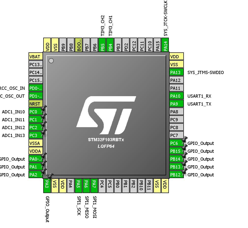
Figure 5 - Selecting the location of the periphery in the program STM32CubeMX
The great beauty of STM is that their “flexibility” allows you to use any legs for I / O, and the entire periphery can be transferred to alternative legs (a fallback), the so-called Remap . All this allows very high quality, fast and convenient to part fee, so beginners learn to use all that gives us the developers of ST.
Now we need to work with the display, that is, light the LEDs in certain situations. Now we go and see how to do it, we need to set our output to log.1 , because the anodes are connected to the MC, and the cathodes with the minus circuit. To do this, open the stm32f10x_gpio.h file and scroll down the file, there is a list of all available functions:
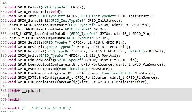
Figure 6 - Functions available when working with GPIO
There we see the functions of setting and resetting the output state:
How to work with such functions: copy it, apparently the first entry in brackets GPIO_TypeDef * GPIOx , as is clear, instead of “x” you need to specify the port, we have ports B and C, we get GPIOB . Here we recall the functions from the beginning of the article, which I requested not to eat too much, it is already time). We look at the second part in the brackets uint16_t GPIO_Pin , here we see the variable GPIO_Pin , we also see that the type of this variable is unsigned, 16 bits in size, that is, 2 16 or 65536 . But we do not need so much, I think it is clear that here we need to specify the number of output (pin) from 0 to 15. As a result, we get GPIO_Pin_12 . Given all this, we write code:
As you can see, every time we remember which leg we connected the LED to, write extra letters, when the code is at least 5,000 lines, oh how important it is)) Therefore, we remember the remarkable feature of the #define command and modify our code:
Now it's unforgettable to make a function that will also turn off our “light bulbs”. To do this, we change the current SetBits function to ResetBits - I think everything is very clear here. We end up with this end code:
Now for simple ignition of the LED it is enough to write LED1_ON; To turn it off, we also write LED1_OFF;
It seems everything is simple? But no! There was the last moment that had to be shown at the beginning, but he would probably have scared half of the people. Although it is simple, but the performance depends on it - this is the initialization of the GPIO periphery . It is necessary to indicate the port from where to get him the clock frequency, on which one to work and in what mode. All this is done in the same stm32f10x_gpio.h library, but now you also need to connect the clocking library stm32f10x_rcc.h to it.
Before you need to do something with any peripherals, you need to enable its clocking , this is done in stm32f10x_rcc.h , go there and see what function to do it, their list is also at the end of the file:

Figure 7 - Clocking Functions
Here we see the familiar APB2 and APB1, the buses to which our ports are connected. In this case, both C and B are on APB2, I highlighted this function on the screen. It is the simplest: in the first part it is necessary to write the name of the periphery, in the second to indicate the status. There can be two statuses : ENABLE (enabled) and DISABLE. Xs why, but it’s important to write status in large letters, otherwise Coco will not highlight the text.
Now you need somewhere to get the correct name of the periphery. Therefore, we go to the library file stm32f10x_rcc.h and presses Ctrl + F - this is a search in the file, write RCC_APB2Periph to it and click Find . And we poke Find several times until we reach such a list, where all the states that this inscription can accept are indicated. Select the desired peripherals:
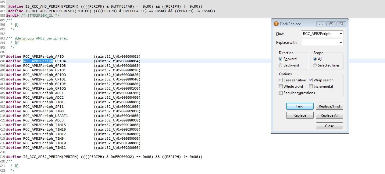
Figure 8 - Search function values by library
And so ... how to enable clocking figured out, we got this line, or rather 2 lines, because use two ports B and C:
Everything, with the clocking library, let's finish it now and go to the stm32f10x_gpio.h file . Go to the end and look for the initialization function, they are usually called Init , there’s a complete captaincy if you know English at least a little. Next, copy the name of the function GPIO_Init and then follow the standard Ctrl + F :
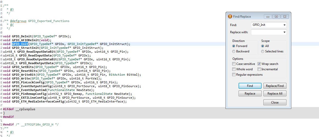
Figure 9 - This is what the function in the list looks like
Next, we poke Find a couple of times until we get to the moment there will be a description of the function and what it looks like:
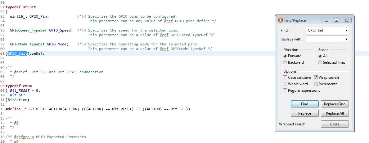
Figure 10 - Initialization Function
so it looks and consists of 3 components:
a) GPIO_Pin - here we indicate how the output is set up
b) GPIO_Speed - here we indicate the speed / frequency maximum at which the controller's foot can work
c) GPIO_Mode - set the foot operation mode
If you select each component, press Ctrl + F and paste and press Find , then there will be a list of what you can write with each component. Now an example of initialization for our case:
Details about the settings can be read in datashit or google, some of the other modes of operation will be found further, so choose how you will study.
I set the maximum frequency to 2 MHz, since in this mode, the periphery consumes a little less current. If this would be a setting for SPI , then you need to specify the maximum, so that there is no limit . I think everything is clear, if not ready to answer in a personal.
As a result, after today's part, we should get such a code . It is for learning, but complementing it in the future we will get the final source: disassembled and understandable to everyone!
As a result, we learned how to adjust the clocking from quartz for high accuracy, disassembled how to use SPL libraries and how to configure GPIO and use them. We also mentioned the main functions of ala define and incloud, with parsing of their application in real code.
Yeah, the article really strained my head, because Sensei is bad for me, and they asked me to tell in detail about the firmware. I hope it worked out for me and those who are only planning to start studying the programming of microcontrollers will be able to understand me, my descriptions and advice.
It so happened that this part is not the last, there will be another 4.3 , where we will analyze the remaining periphery and complete the program. , , .
4.3 , . — , .
— « 0-60 20». , .
Part 5
Part 6
Part 2
Part 3
Part 4.1
Prologue
Opinions were different about the analysis of the code and its necessity in general. In this article I tried to implement the “golden section” method, therefore:
a) at the end of the article the source code will be attached to the
b) I will give the algorithm of work and analyze it
c) explain how to use SPL libraries
d) in the volume of the article I will tell you how to use a certain periphery, I will show the implementation of working with it in the code
e) I will describe in a separate paragraph work with ILI9341, since the topic is quite chewed up, then I’ll just tell you about the main thing - how to think about implementing the initialization function (on the Internet I saw only a code with the phrase: “here’s the initialization, copy and don’t think about it”) and run it through hardware SPI.
Too detailed analysis of the code you will not see here, everything will be in moderation, otherwise I will have to write a book of pages in 200-250. Therefore, study datasheets and other documentation ( links will be ) before you start writing a program. Those who sit for the first time in the MK - do not be afraid if I have any questions, I will tell you and help, so you will master this code.
What is the development environment and is it possible to make life easier for libraries?
I will say right away - the code in this article is not “native”, but it has been tested and it works! Since IAR is not the most convenient software for newbies, and somehow many people bypass it because of too much functionality or even some other reasons, it was decided for the educational article to move the project to “coconut” ( CooCoxIDE 1.7.7 ). I also decided to move away from the registers and write the code in SPL.
')
SPL - is the standard library from ST to work with the periphery of the MK STM32. Now the replacement came new libraries HAL, but so far they have not supplanted the first in many projects. You can deduct advantages and advantages in Google.
I chose SPL - because I like the final code more after the “hard optimization”, they are more intuitive, HAL is more adapted to work with various RTOS. This is purely my opinion, I do not ask anyone to take it on faith and tell in the comments that it is better or worse, not worth it.
As I wrote above - there was a transition from registers to libraries, what is the difference:
Pros:
a) readability of code written using SPL is simply excellent, and in articles with a bias for learning this is the most important thing;b) the speed of writing the code is much higher, it took me 1.5 hours to write the code from scratch for the existing algorithm and debug it;
c) easier moving from stone to stone, well, suddenly you do not have STM32F103RBT6, but there is STM32F105VCT6 and you will be collecting on it.
Minuses:
a) SPL functions are more cumbersome and take up more memory, and also take longer to execute. But this applies only to the initialization functions, everything else has the same speed;b) in datasheets, all parsing is done on registers and this is the main disadvantage.
My result:
You can safely work in CoIDE and write programs using SPL exactly to the level while you consider yourself an amateur. As soon as you have a goal to design serious devices or start making money with electronics - immediately transfer to IAR and smoke datasheets with their registers.We make the algorithm of our program
To begin, let's figure out the
Figure 1 - Flowchart for the control program
Now we can see what our part of the device should measure and how to deal with the data obtained. All measured voltages and currents should be output to the TFT panel, whether the voltage falls within the normal range ( according to GOST ), and at the end multiply the output current with the output voltage and obtain the power consumption of the load. It seems that everything is simple and clear.
Also, our board should measure the temperature, display it on the screen, in case of emergency, 85 o C should turn off the device by filing a log. 1 on the feet of the SD driver IR2110 in the power boards. As well as according to the results of the measured temperature, the value of the duty ratio of the PWM controlling the coolers should be regulated.
All alarm conditions should also be displayed on the LED display, which is used to display
The functionality of this unit is not complicated, and therefore it will not be difficult to implement it.
What needs to be done before continuing to study the article?
1) Download the software with which we will work. This will be CooCoxIDE 1.7.7 , below I have attached a reference to my poison, where you can download the folder with this version of the program, already with SPL installed in it, as well as with the already downloaded compiler so that you don’t suffer and do not search. Everything to start work there is:
CooCoxIDE 1.7.7
2) Download the holy manuscript called datashit on STM32F103 :
Datasheet STM32F103
3) Download at least a scripture called reference manual, which is Googleed as RM0008 and has an epic volume of 1128 pages. This is the most extensive scientific writing that I have mastered, although there were still all volumes of Landau-Livshits, but there are several books all the same ... I’m for something - I advise you to refer to this file with any misunderstandings and curiosities.
RM0008
4) Another very strongly I advise the blog of one boy with a level of knowledge of ST - God, he has there chewed a periphery for beginners and quite complex and interesting tasks:
Nikolay Gorbunov
5) And the last ... run to download a very useful program STM32CubeMX - Official site ST
I hope you downloaded everything that I advised you and now you can start writing the program.
We collect the project
1) We choose the periphery with which we have to work
Figure 2 - A repository for selecting the periphery that we will use
Now briefly who and for what answers:
a) CMSIS core - first of all we tick on this library, several more libraries will be connected immediately. This is the minimum you can work with. This library, as its name implies, connects the “core”, the basic functions through which the rest of the peripherals will work
b) The RCC is the library responsible for the clocking of the microcontroller, this is a separate tricky moment that I will consider today. This library allows you to select the source of generation, as well as set the frequency division factor for each periphery.
c) GPIO - library of work with input / output ports. It also allows you to carry out all the initial settings for the rest of the periphery.
d) DMA - this library allows you to work with direct memory access. This can be read in great detail on the Internet - the topic is chewed, for beginners it is enough to understand that this principle allows increasing the speed of the entire device.
e) SPI - a library for working with the SPI interface, which allows you to exchange data with a bunch of devices. In our case, through it we communicate with the TFT screen on the ILI9341 .
f) TIM - a library for working with a timer. Here I think everything is clear, it will allow us to run PWM to control the coolers and of course to implement delays and generate interrupts.
g) ADC is a library for working with our main periphery with an analog-to-digital converter (ADC), which measures all of our voltages and currents.
We proceed to writing the program.
I was not going to give lessons on C , but since I am guided by an audience of people who were afraid to take up studying MK and I want to push them, I will describe the main points. The first 2 teams:
1) define is a command that serves to substitute one value instead of another. Half here did not understand, as I did when I studied)
Example 1:
We have a program that lights the LED with the team GPIO_SetBits (GPIOA, GPIO_Pin_1); and turns it off with the command GPIO_ResetBits (GPIOA, GPIO_Pin_1); . Now you do not need to think about these commands. As you can see, the command is quite complicated and in the process of writing the code you don’t want to rewrite it 100 times, and even more so you don’t want to remember how to turn on / off the LED every time. Therefore, we proceed as follows, we write:
#define LED_ON GPIO_SetBits(GPIOA, GPIO_Pin_1) #define LED_OFF GPIO_ResetBits(GPIOA, GPIO_Pin_1) What have we done? And simplify your life. Now every time we write in the text of the program LED_ON; ( semicolon is required ), then this phrase will be replaced with the GPIO_SetBits command (GPIOA, GPIO_Pin_1); The same with shutdown.
Example 2:
You write a program that counts the days of the year. In order not to write the number 365 in the program each time (and in fact there can be any complex number, even though Pi), we act like the previous example and write:
#define Year 365 It is worth noting that since 365 is just a constant and not a command, there is no need to put a semicolon after it. Otherwise, it will insert not 365 , but 365; and when used in the same formula will be perceived as an error.
The #define X1 Y2 command simply replaces all X1 with Y2 in the code.
I hope there are no questions left and go to a simpler, but perhaps the most important team:
2) include - it allows us to attach other files and libraries to our code.
Example 1:
Any code, including ours, will begin with this command! We selected library ticks in the repository and Coconut took and copied the files with libraries into the folder with our project. This is not enough, we need to attach them in our main file .
I have not yet begun to attach all the libraries, ADCs, timers, etc. that we mentioned above and did not add here. Attached the main library, so at this stage not to bother. We get this code:
#include "stm32f10x_conf.h" #include "stm32f10x_rcc.h" #include "stm32f10x.h" #include "stm32f10x_gpio.h" #include "stm32f10x_spi.h" #include "TFT ILI9341.h" To understand where we got this incomprehensible file, you need to look into the project tree:
Figure 3 - Project Tree with Required Libraries
As you can see, all that we have attached is in this "tree". This is a library of CMSIS and others. Here you should pay attention to four points:
a) I think the moment with the connection is clear, but I will clarify - #include the “file name” This is how you should include the file, indicating its name in brackets and do not put a semicolon at the end of the line.
b) if you noticed, then I connect only files with the extension .h , you should always do this way. What is the difference between a file with a .h extension and a file with a .c extension ?
c) there are 2 files when using SPL libraries, which are always connected to main .
#include "stm32f10x_conf.h" #include "stm32f10x.h" d) apparently the file font.h I did not connect to the main file main , since I have it connected in the TFT library file ILI9341.h Why is that? FONT is a library with fonts and is used only in the functions of working with the TFT panel. In order not to clutter up the main file, I attached fonts using #include inside the TFT file ILI9341.h .
3) Differences between .h and .c files
Any decent library consists of two files, one of them has the .c permission. This file contains all the functions and their implementations. The file with this extension is the main one for the .h file and therefore is attached inside the latter.
The second part of the library file .h contains just all the necessary inclusions, such as FONT for TFT ILI9341 . It also describes all define , declared constants. To work with this library, as you saw above, we include this particular file, and the .c file comes as a “tail” inside .h
Fuh ... everything, if your brain doesn’t explode, then just relax, have some tea and go on for the most interesting.
Clocking microcontrollers STM32
Getting to the most responsible and cunning item. Clocking STM ok is not like AVR and peaks. There, the frequency of quartz is simply taken and chased into stone.
The STM32 is done like this:
a) MK always starts from HSI - this is an internal 8 MHz oscillator
b) Then the MK switches to HSE - this is an external quartz resonator
c) Next, the signal goes to the PLL, where the frequency is multiplied and goes to the periphery.
It is because of the last point, when I switched to STMs, I had a stupor: I connected the quartz to 8 MHz, and everything works at 72 MHz. Therefore, typical quartz is 8, 16, 24 MHz. Further, the frequency is multiplied inside the microcontroller.
All this can be seen in the following diagram from the datasheet, it is on page 14. That is why I included this manuscript in the mandatory)
Figure 4 - The timing scheme of the periphery of the microcontroller STM32
I also ask you to note that when the clock frequency is taken from the PLL (frequency multiplier) and then distributed around the periphery and set using a divider. There are two buses: APB2 and APB1 , on each hanging a certain periphery. Each bus has a frequency limit: 72 MHz for APB2 and 36 MHz for APB1, that is, on the 1st bus, the frequency is equal to 1/2 of the clock frequency with PLL .
Let me give an example: with SPI1, the power comes from the APB2 bus with a maximum frequency of 72 MHz, and the SPI2 hangs on the APB1 bus with a frequency of 36 MHz and this means that the SPI2 speed will be lower. It is worth considering!
Now let's turn to the function that performs all the tire settings. The RCC library is responsible for clocking, so the function should be searched for in the stm32f10x_rcc.h file, which we connected to our project at the very beginning.
void RCC_Configuration(void) { RCC_DeInit(); // reset RCC_HSEConfig(RCC_HSE_ON); // HSE ( ) HSEStartUpStatus = RCC_WaitForHSEStartUp(); // if (HSEStartUpStatus == SUCCESS) // , { RCC_HCLKConfig(RCC_SYSCLK_Div1); // 1 (Div1), 72 RCC_PCLK2Config(RCC_HCLK_Div1); // APB2 PLL 72 RCC_PCLK1Config(RCC_HCLK_Div1); // APB1 PLL 72 RCC_ADCCLKConfig(RCC_PCLK2_Div2); // 2 (Div2) 36 72 RCC_PLLConfig(RCC_PLLSource_PREDIV1, RCC_PLLMul_9); // 9, 8 * 9 = 72 PLL RCC_PLLCmd(ENABLE); // PLL while (RCC_GetFlagStatus(RCC_FLAG_PLLRDY) == RESET) {} // PLL RCC_SYSCLKConfig(RCC_SYSCLKSource_PLLCLK); // PLL while (RCC_GetSYSCLKSource() != 0x08) {} // PLL } } And now let's remember that before using a function, you need to declare it at the beginning of the program, so in the end we will get such a piece of code that will customize your clocking. It will work on any MK F10x series, so you can save it as a library:
/*************************************** **********************************/ void RCC_Configuration(void); ErrorStatus HSEStartUpStatus; RCC_ClocksTypeDef RCC_Clocks; void RCC_Configuration(void) { RCC_DeInit(); // reset RCC_HSEConfig(RCC_HSE_ON); // HSE ( ) HSEStartUpStatus = RCC_WaitForHSEStartUp(); // if (HSEStartUpStatus == SUCCESS) // , { RCC_HCLKConfig(RCC_SYSCLK_Div1); // 1 (Div1) 72 RCC_PCLK2Config(RCC_HCLK_Div1); // APB2 PLL 72 RCC_PCLK1Config(RCC_HCLK_Div1); // APB1 PLL 72 RCC_ADCCLKConfig(RCC_PCLK2_Div2); // 2 (Div2) 36 72 RCC_PLLConfig(RCC_PLLSource_PREDIV1, RCC_PLLMul_9); // 9, 8 * 9 = 72 PLL RCC_PLLCmd(ENABLE); // PLL while (RCC_GetFlagStatus(RCC_FLAG_PLLRDY) == RESET) {} // PLL RCC_SYSCLKConfig(RCC_SYSCLKSource_PLLCLK); // PLL while (RCC_GetSYSCLKSource() != 0x08) {} // PLL } } I think the clocking I described more or less in detail, now I need to disassemble the periphery.
Work with I / O ports
GPIO is our input / output ports. This is the foundation of before using any other peripherals, it is necessary to configure the ports to which it is derived.
I will lead the story about this periphery using the example of the LED display in our circuit. From the previous article we will take the connection:
a) LED №1 (LED1) is connected to PB12
b) LED No. 2 (LED2) is connected to PB13
c) LED №3 (LED3) is connected to PB14
d) LED №4 (LED4) is connected to PB15
e) LED No. 5 (LED5) is connected to the PC6
What does this mean ... STM has ports, they have 16 pins from 0 to 15. True, there are exceptions, some ports do not always have 16 legs, but they can, for example, only 4 or 5. The designation PB12 means that this is port B and 12th conclusion. Now open the previously downloaded STM32CubeMX and see where these legs are and whether it will be convenient for us to plant them.
Figure 5 - Selecting the location of the periphery in the program STM32CubeMX
The great beauty of STM is that their “flexibility” allows you to use any legs for I / O, and the entire periphery can be transferred to alternative legs (a fallback), the so-called Remap . All this allows very high quality, fast and convenient to part fee, so beginners learn to use all that gives us the developers of ST.
Now we need to work with the display, that is, light the LEDs in certain situations. Now we go and see how to do it, we need to set our output to log.1 , because the anodes are connected to the MC, and the cathodes with the minus circuit. To do this, open the stm32f10x_gpio.h file and scroll down the file, there is a list of all available functions:
Figure 6 - Functions available when working with GPIO
There we see the functions of setting and resetting the output state:
void GPIO_SetBits(GPIO_TypeDef* GPIOx, uint16_t GPIO_Pin); void GPIO_ResetBits(GPIO_TypeDef* GPIOx, uint16_t GPIO_Pin); How to work with such functions: copy it, apparently the first entry in brackets GPIO_TypeDef * GPIOx , as is clear, instead of “x” you need to specify the port, we have ports B and C, we get GPIOB . Here we recall the functions from the beginning of the article, which I requested not to eat too much, it is already time). We look at the second part in the brackets uint16_t GPIO_Pin , here we see the variable GPIO_Pin , we also see that the type of this variable is unsigned, 16 bits in size, that is, 2 16 or 65536 . But we do not need so much, I think it is clear that here we need to specify the number of output (pin) from 0 to 15. As a result, we get GPIO_Pin_12 . Given all this, we write code:
GPIO_SetBits(GPIOB, GPIO_Pin_12); // № 1 GPIO_SetBits(GPIOB, GPIO_Pin_13); // № 2 GPIO_SetBits(GPIOB, GPIO_Pin_14); // № 3 GPIO_SetBits(GPIOB, GPIO_Pin_15); // № 4 GPIO_SetBits(GPIOC, GPIO_Pin_6); // № 5 As you can see, every time we remember which leg we connected the LED to, write extra letters, when the code is at least 5,000 lines, oh how important it is)) Therefore, we remember the remarkable feature of the #define command and modify our code:
#define LED1_ON GPIO_SetBits(GPIOB, GPIO_Pin_12) // № 1 #define LED2_ON GPIO_SetBits(GPIOB, GPIO_Pin_13) // № 2 #define LED3_ON GPIO_SetBits(GPIOB, GPIO_Pin_14) // № 3 #define LED4_ON GPIO_SetBits(GPIOB, GPIO_Pin_15) // № 4 #define LED5_ON GPIO_SetBits(GPIOC, GPIO_Pin_6) // № 5 Now it's unforgettable to make a function that will also turn off our “light bulbs”. To do this, we change the current SetBits function to ResetBits - I think everything is very clear here. We end up with this end code:
#define LED1_ON GPIO_SetBits(GPIOB, GPIO_Pin_12) // № 1 #define LED2_ON GPIO_SetBits(GPIOB, GPIO_Pin_13) // № 2 #define LED3_ON GPIO_SetBits(GPIOB, GPIO_Pin_14) // № 3 #define LED4_ON GPIO_SetBits(GPIOB, GPIO_Pin_15) // № 4 #define LED5_ON GPIO_SetBits(GPIOC, GPIO_Pin_6) // № 5 #define LED1_OFF GPIO_ResetBits(GPIOB, GPIO_Pin_12) // № 1 #define LED2_OFF GPIO_ResetBits(GPIOB, GPIO_Pin_13) // № 2 #define LED3_OFF GPIO_ResetBits(GPIOB, GPIO_Pin_14) // № 3 #define LED4_OFF GPIO_ResetBits(GPIOB, GPIO_Pin_15) // № 4 #define LED5_OFF GPIO_ResetBits(GPIOC, GPIO_Pin_6) // № 5 Now for simple ignition of the LED it is enough to write LED1_ON; To turn it off, we also write LED1_OFF;
It seems everything is simple? But no! There was the last moment that had to be shown at the beginning, but he would probably have scared half of the people. Although it is simple, but the performance depends on it - this is the initialization of the GPIO periphery . It is necessary to indicate the port from where to get him the clock frequency, on which one to work and in what mode. All this is done in the same stm32f10x_gpio.h library, but now you also need to connect the clocking library stm32f10x_rcc.h to it.
Before you need to do something with any peripherals, you need to enable its clocking , this is done in stm32f10x_rcc.h , go there and see what function to do it, their list is also at the end of the file:
Figure 7 - Clocking Functions
Here we see the familiar APB2 and APB1, the buses to which our ports are connected. In this case, both C and B are on APB2, I highlighted this function on the screen. It is the simplest: in the first part it is necessary to write the name of the periphery, in the second to indicate the status. There can be two statuses : ENABLE (enabled) and DISABLE. Xs why, but it’s important to write status in large letters, otherwise Coco will not highlight the text.
Now you need somewhere to get the correct name of the periphery. Therefore, we go to the library file stm32f10x_rcc.h and presses Ctrl + F - this is a search in the file, write RCC_APB2Periph to it and click Find . And we poke Find several times until we reach such a list, where all the states that this inscription can accept are indicated. Select the desired peripherals:
Figure 8 - Search function values by library
And so ... how to enable clocking figured out, we got this line, or rather 2 lines, because use two ports B and C:
RCC_APB2PeriphClockCmd(RCC_APB2Periph_GPIOC, ENABLE); RCC_APB2PeriphClockCmd(RCC_APB2Periph_GPIOB, ENABLE); Everything, with the clocking library, let's finish it now and go to the stm32f10x_gpio.h file . Go to the end and look for the initialization function, they are usually called Init , there’s a complete captaincy if you know English at least a little. Next, copy the name of the function GPIO_Init and then follow the standard Ctrl + F :
Figure 9 - This is what the function in the list looks like
Next, we poke Find a couple of times until we get to the moment there will be a description of the function and what it looks like:
Figure 10 - Initialization Function
so it looks and consists of 3 components:
a) GPIO_Pin - here we indicate how the output is set up
b) GPIO_Speed - here we indicate the speed / frequency maximum at which the controller's foot can work
c) GPIO_Mode - set the foot operation mode
If you select each component, press Ctrl + F and paste and press Find , then there will be a list of what you can write with each component. Now an example of initialization for our case:
RCC_APB2PeriphClockCmd(RCC_APB2Periph_GPIOC, ENABLE); // GPIO_InitTypeDef led; // led led.GPIO_Pin = (GPIO_Pin_12 | GPIO_Pin_13 | GPIO_Pin_14 | GPIO_Pin_15) ; // led.GPIO_Speed = GPIO_Speed_2MHz; // led.GPIO_Mode = GPIO_Mode_Out_PP; // , push-pull GPIO_Init(GPIOB, &led); // Details about the settings can be read in datashit or google, some of the other modes of operation will be found further, so choose how you will study.
I set the maximum frequency to 2 MHz, since in this mode, the periphery consumes a little less current. If this would be a setting for SPI , then you need to specify the maximum, so that there is no limit . I think everything is clear, if not ready to answer in a personal.
As a result, after today's part, we should get such a code . It is for learning, but complementing it in the future we will get the final source: disassembled and understandable to everyone!
#include "stm32f10x_conf.h" #include "stm32f10x_rcc.h" #include "stm32f10x.h" #include "stm32f10x_gpio.h" #include "stm32f10x_spi.h" #include "TFT ILI9341.h" #define LED1_ON GPIO_SetBits(GPIOB, GPIO_Pin_12) // № 1 #define LED2_ON GPIO_SetBits(GPIOB, GPIO_Pin_13) // № 2 #define LED3_ON GPIO_SetBits(GPIOB, GPIO_Pin_14) // № 3 #define LED4_ON GPIO_SetBits(GPIOB, GPIO_Pin_15) // № 4 #define LED5_ON GPIO_SetBits(GPIOC, GPIO_Pin_6) // № 5 #define LED1_OFF GPIO_ResetBits(GPIOB, GPIO_Pin_12) // № 1 #define LED2_OFF GPIO_ResetBits(GPIOB, GPIO_Pin_13) // № 2 #define LED3_OFF GPIO_ResetBits(GPIOB, GPIO_Pin_14) // № 3 #define LED4_OFF GPIO_ResetBits(GPIOB, GPIO_Pin_15) // № 4 #define LED5_OFF GPIO_ResetBits(GPIOC, GPIO_Pin_6) // № 5 /****************************************************************************************************************/ /********************** **********************************************************/ /****************************************************************************************************************/ /*************************************** **********************************/ void RCC_Configuration(void); ErrorStatus HSEStartUpStatus; RCC_ClocksTypeDef RCC_Clocks; void RCC_Configuration(void) { RCC_DeInit(); // reset RCC_HSEConfig(RCC_HSE_ON); // HSE ( ) HSEStartUpStatus = RCC_WaitForHSEStartUp(); // if (HSEStartUpStatus == SUCCESS) // , { RCC_HCLKConfig(RCC_SYSCLK_Div1); // 1 (Div1) 72 RCC_PCLK2Config(RCC_HCLK_Div1); // APB2 PLL 72 RCC_PCLK1Config(RCC_HCLK_Div1); // APB1 PLL 72 RCC_ADCCLKConfig(RCC_PCLK2_Div2); // 2 (Div2) 36 72 RCC_PLLConfig(RCC_PLLSource_PREDIV1, RCC_PLLMul_9); // 9, 8 * 9 = 72 PLL RCC_PLLCmd(ENABLE); // PLL while (RCC_GetFlagStatus(RCC_FLAG_PLLRDY) == RESET) {} // PLL RCC_SYSCLKConfig(RCC_SYSCLKSource_PLLCLK); // PLL while (RCC_GetSYSCLKSource() != 0x08) {} // PLL } } /************************** ***********************************************/ /**************************************************************************************************/ /**************************************************************************************************/ int main(void) { RCC_GetClocksFreq (&RCC_Clocks); RCC_Configuration(); RCC_GetClocksFreq (&RCC_Clocks); /************* *****************************************/ RCC_APB2PeriphClockCmd(RCC_APB2Periph_GPIOC, ENABLE); // GPIO_InitTypeDef led; // led led.GPIO_Pin = (GPIO_Pin_12 | GPIO_Pin_13 | GPIO_Pin_14 | GPIO_Pin_15) ; // led.GPIO_Speed = GPIO_Speed_2MHz; // led.GPIO_Mode = GPIO_Mode_Out_PP; // , push-pull GPIO_Init(GPIOB, &led); // while(1) { LED1_ON; LED2_OFF; LED3_ON; LED4_ON; LED5_OFF; } } As a result, we learned how to adjust the clocking from quartz for high accuracy, disassembled how to use SPL libraries and how to configure GPIO and use them. We also mentioned the main functions of ala define and incloud, with parsing of their application in real code.
Epilogue
Yeah, the article really strained my head, because Sensei is bad for me, and they asked me to tell in detail about the firmware. I hope it worked out for me and those who are only planning to start studying the programming of microcontrollers will be able to understand me, my descriptions and advice.
It so happened that this part is not the last, there will be another 4.3 , where we will analyze the remaining periphery and complete the program. , , .
4.3 , . — , .
— « 0-60 20». , .
Part 5
Part 6
Source: https://habr.com/ru/post/358324/
All Articles