Calculation and manufacture of the "heart" of the IIP - pulse transformer. Part 2
Part 1
And yet I was invited! Now deal with articles go more quickly. The topic of the next part, initially, I wanted to make the circuitry of a block, but why wait? But then I remembered my school youth and the very great problem I was faced with - how to make an impulse transformer unknown to me at the time of thebeast . Ten years have passed and I understand that many (and not only beginners) radio amateurs, electronics engineers and students have such difficulties - they are simply afraid of them, and as a result try to avoid high-power switching power supplies (hereinafter, IIP ).
After these reflections, I came to the conclusion that the first topic should be about the transformer and about nothing else! I would also like to make a reservation: what do I mean by the term “powerful SMPS” - these are capacities from 1 kW and above, or in the case of amateurs at least 500 watts.
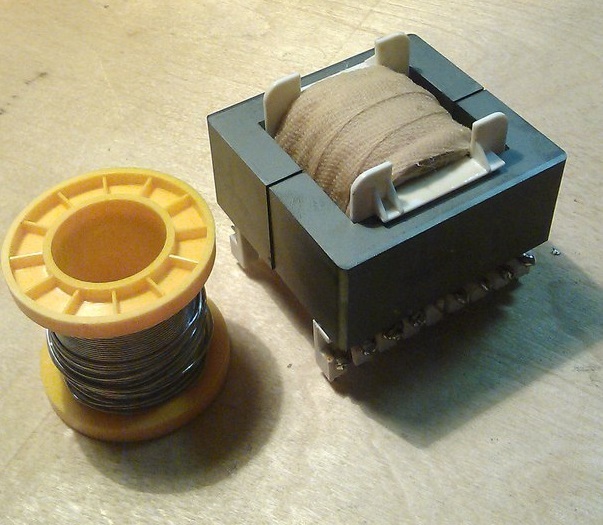
Figure 1 - Here is a 2 kW transformer for the N-bridge, we will end up with
Having once introduced impulse technology into my arsenal, I thought that transformers could be made only on ferrite available to all. Having collected the first constructions, the first thing I decided to put them on the court of the more experienced comrade, and very often heard the following phrase: “Your shitty ferrite is not the best material for the impulse . ” Immediately, I decided to find out from them what kind of alternative you could oppose him and I was told - alsifer or what is also called syndast.
')
First you need to decide what should be able to almost perfect material for a transformer:
1) it must be magnetically soft , that is, it is easy to magnetize and demagnetize:

Figure 2 - Hysteresis cycles of ferromagnets: 1) hard cycle, 2) soft cycle
2) the material should have as much as possible saturation induction, which will allow either to reduce the dimensions of the core, or, if they remain, to increase the power.
3) the material should have the lowest possible loss of magnetization reversal and Foucault currents
4) the properties of the material should not greatly change under external influence: mechanical forces (compression or tension), changes in temperature and humidity.
Ferrite - is a semiconductor, and therefore has its own high electrical resistance. This means that at high frequencies the eddy current losses ( Foucault currents) will be quite low. It turns out at least one of the conditions from the list above, we have already fulfilled. Go ahead…
Ferrites are thermostable and unstable, but this parameter is not decisive for SMPS. It is important that ferrites work stably in the temperature range from -60 to +100 o C and this is the case of the simplest and cheapest brands.

Figure 3 - Magnetization curve at a frequency of 20 kHz at different temperatures
And finally, the most important point - on the graph above, we saw a parameter that will determine almost everything - saturation induction . For ferrite, it is usually taken 0.39 T. It is worth remembering that under different conditions - this parameter will change. It depends on both the frequency and the working temperature and on other parameters, but special emphasis should be placed on the first two.
Conclusion: ferritenishtyak! Great for our tasks.
1) The alsifer works in a slightly wider range of temperatures: from -60 to +120 o C - suitable? Even better than ferrite!
2) the hysteresis loss factor of the alsifer is constant only in weak fields (at low power), they grow in a powerful field and very much - this is a very serious minus, especially at powers above 2 kW, so it loses here.
3) induction of saturation up to 1.2 Tl! 4 times more than ferrite! - the main parameter and so overtakes, but not everything is so simple ... Of course, this dignity will not go anywhere, but paragraph 2 weakens it and very much - definitely a plus.
Conclusion: alsifer is better than ferrite, I was not lied to this uncle.
The result of the battle: anyone reading the description above will tell us alsifer give us! And rightly so ... but try to find a core of alsifer and so with an overall power of 10 kW? There is usually a person comes to a standstill, it turns out they are not particularly for sale, and if there is, then to order directly from the manufacturer and the price will scare you.
It turns out that we use ferrite, especially if we evaluate it as a whole, then it loses very little ... ferrite is evaluated relative to the alsifer in "8 out of 10 parrots".
I wanted to address my beloved matan, but decided not to, because 10 000 characters to the article I consider redundant. I can only advise a book with very good calculations of the authorship of B. Semenov "Power electronics: from simple to complex." I don’t see any sense in retelling his calculations with some additions
First of all, I want to immediately recall a very serious moment - the gap in the core. He can "kill" all the power or add another 30-40%. I want to remind you that we are making a transformer for the N-bridge , and it refers to - forward-through converters (forward in bourgeois). This means that the clearance should ideally be 0 mm.
Once, while studying a course of 2-3, I decided to assemble a welding inverter, I turned to the topology of the Kemppi inverters. There I saw a transformer gap of 0.15 mm. It became interesting for what is it. He did not approach the teachers, but took and called the Russian representative office of Kemppi! And what to lose? To my surprise, I was connected to a circuit engineer, and he told me a few theoretical points that allowed me to “crawl out” over a 1 kW ceiling.
If in short - a gap of 0.1-0.2 mm is simply necessary! This increases the demagnetization rate of the core, which allows pumping more power through the transformer. The maximum effect of such afeint with the ears of the gap reached in the topology "oblique bridge" , there the introduction of a gap of 0.15 mm gives a gain of 100%! In our H-bridge, this increase is more modest, but 40-60% I think is also not bad.
For the manufacture of a transformer, we need this set:
but)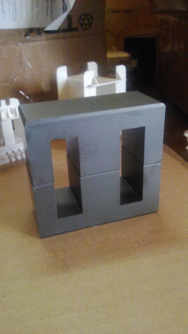
Figure 4 - Ferrite core E70 / 33/32 from material 390 (slightly better analogue of N87)
b)
Fig 5 - Frame for core E70 / 33/32 (the one that is larger) and choke iron choke D46
Overall power of such a transformer is 7.2 kW. We need such a reserve to provide starting currents 6–7 times the nominal (600% of the TZ). Such starting currents are true only in asynchronous motors, but you need to consider everything!
Unexpectedly, a certain choke “surfaced”, it will be needed in our further scheme (as many as 5 pieces) and therefore decided to show how to wind it.
Next, you need to calculate the winding parameters. I use the program from a friend in certain circles, Comrade Starichok51 . A person with great knowledge and always ready to teach and help, for which he thanks - in his time helped to take the right path. The program is called - ExcellentIT 8.1 .
I give an example of calculation for 2 kW:
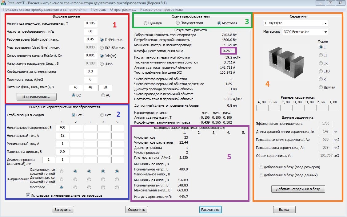
Figure 6 - Calculation of a pulse transformer on a 2 kW boost circuit
1) Highlighted in red. These are the input parameters, which are usually set by default:
a) maximum induction. Remember, for ferrite, it is 0.39 Tl, but our transformer operates at a sufficiently high frequency, so the program exposes 0.186 itself. This is the induction of saturation in very bad conditions, including heating to 125 degrees
b) the frequency of conversion, it is set by us and how it is defined on the diagram will be in the following articles. This frequency should be from 20 to 120 kHz. If less - we will hear the work of trance and whistling, if higher , then our keys (transistors) will have large dynamic losses. And IGBT keys, even expensive work up to 150 kHz
c) coefficient filling the window is an important parameter, because the space on the frame and the core is limited, you should not make it more than 0.35 otherwise the windings will not fit
d) current density - this parameter can be up to 10 A / mm 2 . This is the maximum current that can flow through a conductor. The optimal value of 5-6 A / mm 2 - in conditions of tough operation: poor cooling, constant operation at full load and so on. 8-10 A / mm 2 - you can set if your device is ideally ventilated and costsover 9000 several coolers.
e) power at the entrance. Since we calculate the transformer for DC-> DC 48V to 400V, then we set the input voltage as in the calculation. Where did the figure come from. In a discharged state, the battery gives 10.5V, further discharge - to reduce the service life, multiply by the number of batteries (4 pieces) and we get 42V. Take with a margin of 40V. 48V is taken from the product 12V * 4 pcs. 58V is taken from the consideration that in the charged state the battery has a voltage of 14.2-14.4V and by analogy we multiply by 4.
2) Highlighted in blue.
a) set 400V, because this margin for voltage feedback and for cutting a sine requires a minimum of 342V
b) rated current. We choose from the consideration 2400 W / 220 (230) V = 12A. As you can see everywhere I take a stock of at least 20%. So does any self-respecting manufacturer of high-quality equipment. In the USSR, such a stock was a reference 25%, even for the most difficult conditions. Why 220 (230) V is the voltage at the output of an already pure sine.
c) minimum current. Chosen from actual conditions, this parameter affects the size of the output choke, so the larger the minimum current, the smaller the choke, and hence the cheaper the device. Again, I chose the worst option 1A, it is a current for 2-3 light bulbs or 3-4 routers.
d) a fall on the diodes. Since If we have ultra-fast diodes at the output, then they drop 0.6V under worse conditions (temperature is exceeded).
e) wire diameter. I once bought a copper coil of 20 kg for such a case and with a diameter of 1 mm. Here we put the one that you have. Only I advise you not to put more than 1.18 mm, because will begin to affect the skin effect
3) Highlighted in green. Everything is simple here - the topology is planned with a “full bridge” and we choose it.
4) Selected orange. The process of selecting the core, everything is intuitive. A large number of standard cores are already in the library, like ours, but if anything can be added by entering the dimensions.
5) Selected purple. Output parameters with calculations. Separate window allocated cal. fill the window, remember - no more than 0.35, and preferably no more than 0.3. All the necessary values are also given: the number of turns for the primary and secondary windings, the number of wires of a previously specified diameter in the "spit" for winding.
The parameters for the further calculation of the output choke are also given: inductance and voltage ripple.
Now you need to calculate the output choke. It is necessary to smooth out the pulsations, as well as to create a "uniform" current. The calculation is carried out in the program of the same author and it is called DrosselRing 5.0 . I will give the calculation for our transformer:

Figure 7 - Calculation of the output choke for step-up DC-DC converter
In this calculation, everything is simpler and clearer, it works on the same principle as the output data: the number of turns and the number of wires in the spit.
Now we have all the data for the manufacture of a transformer and a choke.
The main rule of winding a pulse transformer - without exception, all windings must be wound in one direction!
Stage 1:
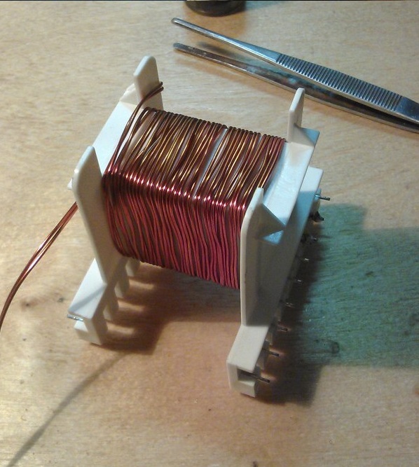
Figure 8 - The process of winding the secondary (high-voltage) winding
We wind on the frame the required number of turns in 2 wires with a diameter of 1 mm. We remember the direction of winding, and better mark the marker on the frame.
Stage 2:

Figure 9 - Isolate the secondary winding
We isolate the secondary winding with a fluoroplastic tape with a thickness of 1 mm, such insulation can withstand at least 1000 V. We also impregnate it with varnish, this is + 600V to insulation. If there is no PTFE tape, then we isolate it with the usual plumbing fum of 4-6 layers. This is the same fluoroplast, only 150-200 microns thick.
Stage 3:

Figure 10 - We start to wind the primary winding, solder the wires on the frame
Winding conduct in one direction with the secondary winding!
Stage 4:

Figure 11 - Display the tail of the primary winding
Winds the winding, we isolate it with the same fluoroplastic tape. It is also desirable to soak the varnish.
Stage 5:

Figure 12 - We saturate with varnish and solder the “tail”. Winding is over
Stage 6:
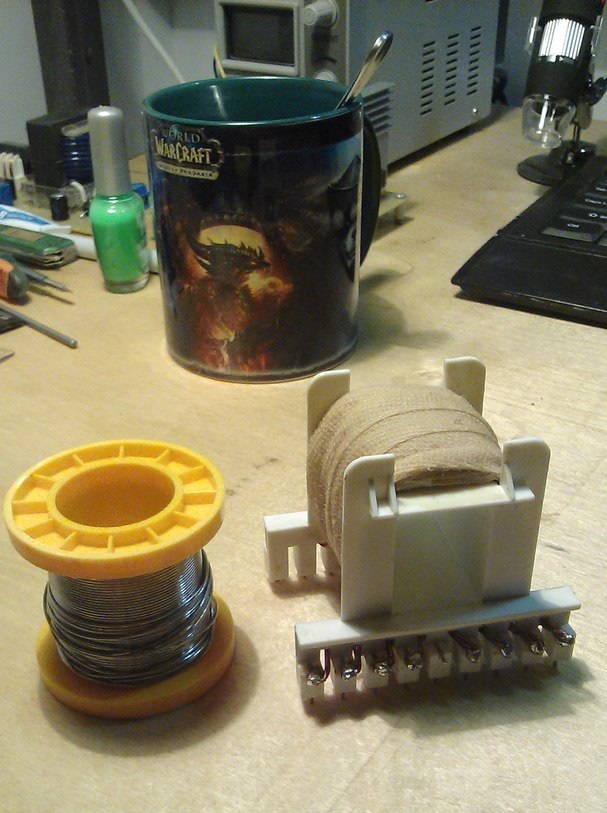
Figure 13 - We complete the winding and insulation of the transformer with a keeper tape with final impregnation in varnish
Stage 7:
Figure 14 - This is the complete version of the transformer.
A gap of 0.15 mm is established in the process of gluing, by inserting a suitable film between the halves of the core. The best option - film for printing. The core is glued together with glue with a moment (good) or epoxy resin. The 1st option for centuries, the 2nd allows in case of something to disassemble the transformer without damage, for example, if you need to wind more winding or add turns.
Now, by analogy, it is necessary to wind the choke, of course to wind on the toroidal core is more difficult, but this option will be more compact. All the data we have from the program, the core material is sprayed iron or permalloy. The saturation induction of this material is 0.55 T.
Stage 1:

Figure 15 - Wrapping the ring with fluoroplastic tape
This operation allows you to avoid the case of a breakdown of the winding on the core, it happens rarely, but we do it for quality and do it for ourselves!
Stage 2:
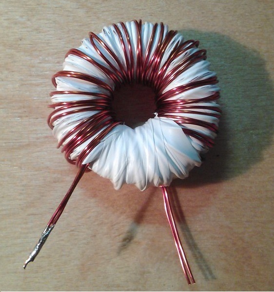
Figure 16 - We wind the required number of turns and isolate
In this case, the number of turns does not fit into one layer of winding, therefore, after winding the first layer, it is necessary to insulate and wind the second layer with subsequent insulation.
Stage 3:

Figure 17 - Isolate after the second layer and soak varnish
I hope my article will teach you the process of calculating and manufacturing a pulse transformer, as well as give you some theoretical concepts about its work and the materials from which it is made. I tried not to burden this part with excessive theory, everything was at a minimum and focus solely on practical issues. And most importantly, on key features that affect performance, such as clearance, winding directions, and so on.
To be continued...
Part 3
Part 4.1
Part 4.2
Part 5
Part 6
Prologue
And yet I was invited! Now deal with articles go more quickly. The topic of the next part, initially, I wanted to make the circuitry of a block, but why wait? But then I remembered my school youth and the very great problem I was faced with - how to make an impulse transformer unknown to me at the time of the
After these reflections, I came to the conclusion that the first topic should be about the transformer and about nothing else! I would also like to make a reservation: what do I mean by the term “powerful SMPS” - these are capacities from 1 kW and above, or in the case of amateurs at least 500 watts.
Figure 1 - Here is a 2 kW transformer for the N-bridge, we will end up with
Great battle or what material to choose?
Having once introduced impulse technology into my arsenal, I thought that transformers could be made only on ferrite available to all. Having collected the first constructions, the first thing I decided to put them on the court of the more experienced comrade, and very often heard the following phrase: “Your shitty ferrite is not the best material for the impulse . ” Immediately, I decided to find out from them what kind of alternative you could oppose him and I was told - alsifer or what is also called syndast.
')
Why is it so good and is it really better than ferrite?
First you need to decide what should be able to almost perfect material for a transformer:
1) it must be magnetically soft , that is, it is easy to magnetize and demagnetize:
Figure 2 - Hysteresis cycles of ferromagnets: 1) hard cycle, 2) soft cycle
2) the material should have as much as possible saturation induction, which will allow either to reduce the dimensions of the core, or, if they remain, to increase the power.
Saturation
The phenomenon of transformer saturation is that, despite the increase in current in the winding, the magnetic flux in the core, having reached a certain maximum value, then practically does not change.
In a transformer, the saturation mode leads to the fact that the transfer of energy from the primary to the secondary winding partially stops. Normal operation of a transformer is possible only when the magnetic flux in its core changes in proportion to the change in current in the primary winding. To fulfill this condition, it is necessary that the core is not in a state of saturation, and this is possible only when its volume and cross section are not less than a well-defined value. Consequently, the greater the power of the transformer, the greater must be its core.
In a transformer, the saturation mode leads to the fact that the transfer of energy from the primary to the secondary winding partially stops. Normal operation of a transformer is possible only when the magnetic flux in its core changes in proportion to the change in current in the primary winding. To fulfill this condition, it is necessary that the core is not in a state of saturation, and this is possible only when its volume and cross section are not less than a well-defined value. Consequently, the greater the power of the transformer, the greater must be its core.
3) the material should have the lowest possible loss of magnetization reversal and Foucault currents
4) the properties of the material should not greatly change under external influence: mechanical forces (compression or tension), changes in temperature and humidity.
Now consider the properties of ferrite and how it meets the requirements presented above.
Ferrite - is a semiconductor, and therefore has its own high electrical resistance. This means that at high frequencies the eddy current losses ( Foucault currents) will be quite low. It turns out at least one of the conditions from the list above, we have already fulfilled. Go ahead…
Ferrites are thermostable and unstable, but this parameter is not decisive for SMPS. It is important that ferrites work stably in the temperature range from -60 to +100 o C and this is the case of the simplest and cheapest brands.
Figure 3 - Magnetization curve at a frequency of 20 kHz at different temperatures
And finally, the most important point - on the graph above, we saw a parameter that will determine almost everything - saturation induction . For ferrite, it is usually taken 0.39 T. It is worth remembering that under different conditions - this parameter will change. It depends on both the frequency and the working temperature and on other parameters, but special emphasis should be placed on the first two.
Conclusion: ferrite
A few words about the alsifer and how it differs
1) The alsifer works in a slightly wider range of temperatures: from -60 to +120 o C - suitable? Even better than ferrite!
2) the hysteresis loss factor of the alsifer is constant only in weak fields (at low power), they grow in a powerful field and very much - this is a very serious minus, especially at powers above 2 kW, so it loses here.
3) induction of saturation up to 1.2 Tl! 4 times more than ferrite! - the main parameter and so overtakes, but not everything is so simple ... Of course, this dignity will not go anywhere, but paragraph 2 weakens it and very much - definitely a plus.
Conclusion: alsifer is better than ferrite, I was not lied to this uncle.
The result of the battle: anyone reading the description above will tell us alsifer give us! And rightly so ... but try to find a core of alsifer and so with an overall power of 10 kW? There is usually a person comes to a standstill, it turns out they are not particularly for sale, and if there is, then to order directly from the manufacturer and the price will scare you.
It turns out that we use ferrite, especially if we evaluate it as a whole, then it loses very little ... ferrite is evaluated relative to the alsifer in "8 out of 10 parrots".
I wanted to address my beloved matan, but decided not to, because 10 000 characters to the article I consider redundant. I can only advise a book with very good calculations of the authorship of B. Semenov "Power electronics: from simple to complex." I don’t see any sense in retelling his calculations with some additions
So, proceed to the calculation and manufacture of the transformer
First of all, I want to immediately recall a very serious moment - the gap in the core. He can "kill" all the power or add another 30-40%. I want to remind you that we are making a transformer for the N-bridge , and it refers to - forward-through converters (forward in bourgeois). This means that the clearance should ideally be 0 mm.
Once, while studying a course of 2-3, I decided to assemble a welding inverter, I turned to the topology of the Kemppi inverters. There I saw a transformer gap of 0.15 mm. It became interesting for what is it. He did not approach the teachers, but took and called the Russian representative office of Kemppi! And what to lose? To my surprise, I was connected to a circuit engineer, and he told me a few theoretical points that allowed me to “crawl out” over a 1 kW ceiling.
If in short - a gap of 0.1-0.2 mm is simply necessary! This increases the demagnetization rate of the core, which allows pumping more power through the transformer. The maximum effect of such a
For the manufacture of a transformer, we need this set:
but)
Figure 4 - Ferrite core E70 / 33/32 from material 390 (slightly better analogue of N87)
b)
Fig 5 - Frame for core E70 / 33/32 (the one that is larger) and choke iron choke D46
Overall power of such a transformer is 7.2 kW. We need such a reserve to provide starting currents 6–7 times the nominal (600% of the TZ). Such starting currents are true only in asynchronous motors, but you need to consider everything!
Unexpectedly, a certain choke “surfaced”, it will be needed in our further scheme (as many as 5 pieces) and therefore decided to show how to wind it.
Next, you need to calculate the winding parameters. I use the program from a friend in certain circles, Comrade Starichok51 . A person with great knowledge and always ready to teach and help, for which he thanks - in his time helped to take the right path. The program is called - ExcellentIT 8.1 .
I give an example of calculation for 2 kW:
Figure 6 - Calculation of a pulse transformer on a 2 kW boost circuit
How to calculate:
1) Highlighted in red. These are the input parameters, which are usually set by default:
a) maximum induction. Remember, for ferrite, it is 0.39 Tl, but our transformer operates at a sufficiently high frequency, so the program exposes 0.186 itself. This is the induction of saturation in very bad conditions, including heating to 125 degrees
b) the frequency of conversion, it is set by us and how it is defined on the diagram will be in the following articles. This frequency should be from 20 to 120 kHz. If less - we will hear the work of trance and whistling, if higher , then our keys (transistors) will have large dynamic losses. And IGBT keys, even expensive work up to 150 kHz
c) coefficient filling the window is an important parameter, because the space on the frame and the core is limited, you should not make it more than 0.35 otherwise the windings will not fit
d) current density - this parameter can be up to 10 A / mm 2 . This is the maximum current that can flow through a conductor. The optimal value of 5-6 A / mm 2 - in conditions of tough operation: poor cooling, constant operation at full load and so on. 8-10 A / mm 2 - you can set if your device is ideally ventilated and costs
e) power at the entrance. Since we calculate the transformer for DC-> DC 48V to 400V, then we set the input voltage as in the calculation. Where did the figure come from. In a discharged state, the battery gives 10.5V, further discharge - to reduce the service life, multiply by the number of batteries (4 pieces) and we get 42V. Take with a margin of 40V. 48V is taken from the product 12V * 4 pcs. 58V is taken from the consideration that in the charged state the battery has a voltage of 14.2-14.4V and by analogy we multiply by 4.
2) Highlighted in blue.
a) set 400V, because this margin for voltage feedback and for cutting a sine requires a minimum of 342V
b) rated current. We choose from the consideration 2400 W / 220 (230) V = 12A. As you can see everywhere I take a stock of at least 20%. So does any self-respecting manufacturer of high-quality equipment. In the USSR, such a stock was a reference 25%, even for the most difficult conditions. Why 220 (230) V is the voltage at the output of an already pure sine.
c) minimum current. Chosen from actual conditions, this parameter affects the size of the output choke, so the larger the minimum current, the smaller the choke, and hence the cheaper the device. Again, I chose the worst option 1A, it is a current for 2-3 light bulbs or 3-4 routers.
d) a fall on the diodes. Since If we have ultra-fast diodes at the output, then they drop 0.6V under worse conditions (temperature is exceeded).
e) wire diameter. I once bought a copper coil of 20 kg for such a case and with a diameter of 1 mm. Here we put the one that you have. Only I advise you not to put more than 1.18 mm, because will begin to affect the skin effect
Skin effect
The skin effect is the effect of decreasing the amplitude of electromagnetic waves as they penetrate deep into the conducting medium. As a result of this effect, for example, an alternating current of high frequency when flowing through a conductor is not distributed evenly over the cross section, but mainly in the surface layer.
If we speak not like Google, but with my kolkhoz language, then if we take a conductor of a large section, then it will not be fully used, since currents at a higher frequency flow across the surface, and the center of the conductor will be "empty"
If we speak not like Google, but with my kolkhoz language, then if we take a conductor of a large section, then it will not be fully used, since currents at a higher frequency flow across the surface, and the center of the conductor will be "empty"
3) Highlighted in green. Everything is simple here - the topology is planned with a “full bridge” and we choose it.
4) Selected orange. The process of selecting the core, everything is intuitive. A large number of standard cores are already in the library, like ours, but if anything can be added by entering the dimensions.
5) Selected purple. Output parameters with calculations. Separate window allocated cal. fill the window, remember - no more than 0.35, and preferably no more than 0.3. All the necessary values are also given: the number of turns for the primary and secondary windings, the number of wires of a previously specified diameter in the "spit" for winding.
The parameters for the further calculation of the output choke are also given: inductance and voltage ripple.
Now you need to calculate the output choke. It is necessary to smooth out the pulsations, as well as to create a "uniform" current. The calculation is carried out in the program of the same author and it is called DrosselRing 5.0 . I will give the calculation for our transformer:
Figure 7 - Calculation of the output choke for step-up DC-DC converter
In this calculation, everything is simpler and clearer, it works on the same principle as the output data: the number of turns and the number of wires in the spit.
Production stages
Now we have all the data for the manufacture of a transformer and a choke.
The main rule of winding a pulse transformer - without exception, all windings must be wound in one direction!
Stage 1:
Figure 8 - The process of winding the secondary (high-voltage) winding
We wind on the frame the required number of turns in 2 wires with a diameter of 1 mm. We remember the direction of winding, and better mark the marker on the frame.
Stage 2:
Figure 9 - Isolate the secondary winding
We isolate the secondary winding with a fluoroplastic tape with a thickness of 1 mm, such insulation can withstand at least 1000 V. We also impregnate it with varnish, this is + 600V to insulation. If there is no PTFE tape, then we isolate it with the usual plumbing fum of 4-6 layers. This is the same fluoroplast, only 150-200 microns thick.
Stage 3:
Figure 10 - We start to wind the primary winding, solder the wires on the frame
Winding conduct in one direction with the secondary winding!
Stage 4:
Figure 11 - Display the tail of the primary winding
Winds the winding, we isolate it with the same fluoroplastic tape. It is also desirable to soak the varnish.
Stage 5:
Figure 12 - We saturate with varnish and solder the “tail”. Winding is over
Stage 6:
Figure 13 - We complete the winding and insulation of the transformer with a keeper tape with final impregnation in varnish
Kiper tape
Kiper ribbon - cotton (less often silk or semi-silk) tape from keeper fabric from 8 to 50 mm wide, twill or diagonal weave; harsh, bleaching or dyed. The material of the tape is distinguished by its high density due to weaving; it is thicker than that of its closest analogue - calico tape - due to the use of thicker threads.
Thank you wikipedia.
Thank you wikipedia.
Stage 7:
Figure 14 - This is the complete version of the transformer.
A gap of 0.15 mm is established in the process of gluing, by inserting a suitable film between the halves of the core. The best option - film for printing. The core is glued together with glue with a moment (good) or epoxy resin. The 1st option for centuries, the 2nd allows in case of something to disassemble the transformer without damage, for example, if you need to wind more winding or add turns.
Winding throttle
Now, by analogy, it is necessary to wind the choke, of course to wind on the toroidal core is more difficult, but this option will be more compact. All the data we have from the program, the core material is sprayed iron or permalloy. The saturation induction of this material is 0.55 T.
Stage 1:
Figure 15 - Wrapping the ring with fluoroplastic tape
This operation allows you to avoid the case of a breakdown of the winding on the core, it happens rarely, but we do it for quality and do it for ourselves!
Stage 2:
Figure 16 - We wind the required number of turns and isolate
In this case, the number of turns does not fit into one layer of winding, therefore, after winding the first layer, it is necessary to insulate and wind the second layer with subsequent insulation.
Stage 3:
Figure 17 - Isolate after the second layer and soak varnish
Epilogue
I hope my article will teach you the process of calculating and manufacturing a pulse transformer, as well as give you some theoretical concepts about its work and the materials from which it is made. I tried not to burden this part with excessive theory, everything was at a minimum and focus solely on practical issues. And most importantly, on key features that affect performance, such as clearance, winding directions, and so on.
To be continued...
Part 3
Part 4.1
Part 4.2
Part 5
Part 6
Source: https://habr.com/ru/post/358318/
All Articles