Designing a powerful double conversion UPS (on-line). Part 1
Prologue
I would like to welcome everyone who is interested in electronics! This series of publications will be devoted to the complete design cycle of a powerful uninterruptible power supply with a power of 3.2 kW and, most importantly, with a pure sine at the output.
I'll tell you a little about myself - I work as an electronics engineer at an enterprise engaged in the production of machine tools and CNC lines, as well as powerful impulse devices: UPS, voltage stabilizers, inverters. Together with the company has gone from the design of systems from 1 kW to 1135 kW.
My publications will be more educational in nature with attempts to convey to interested people the basics of power calculations, circuit tracing and RF circuits, programming STM32 microcontrollers, as well as Altera FPGAs. And of course there are many more complex, but interesting things. Perhaps we start ...
And why did he suddenly need this pure sine and UPS in general?
These devices are needed to create autonomous systems both in production and in everyday life. As an occupant of a private house, I myself face problems in the supply of electricity. The use of UPS allows to ensure the normal functioning of the main systems at home, such as:
')
- heating system;
- work well and submersible pump;
- backup home server;
- ensuring the smooth operation of routers;
- Banal provision of lighting in the house.
Everything above is the problems that we can face. They are global, but is it worth making a UPS at all? After a couple of hours without light and you can wait!
This is partly correct, but I am used to living in a civilized world. Then we turn to production, why is there a reservation? From my experience I will describe several major problems:
- the need to ensure uninterrupted operation of conveyor lines;
- ensuring the autonomy of data centers, servers, companies and other networks from power cuts;
- protection of expensive equipment against overvoltage, undervoltage and short circuits;
Everything seems to be clearing up! It remains to decide: "why exactly pure sine?"
This question has a place to be, because 80% of modern devices have a built-in switching power supply, which allows them to be supplied with direct current with a voltage of + 310V. It remains to understand what is in the remaining 20% ...
These are mainly systems and devices where there are three-phase motors (asynchronous), as well as high-precision equipment and so on. If you think about it, then this category will get 90% of the equipment in production + to everything else and such household devices as boiler equipment, circulation pumps in underfloor heating and heating, and a pump for wells.
It turned out quite a serious reason to do design!
What do you get after studying a series of articles?
I will not torment, but you will get the following device:
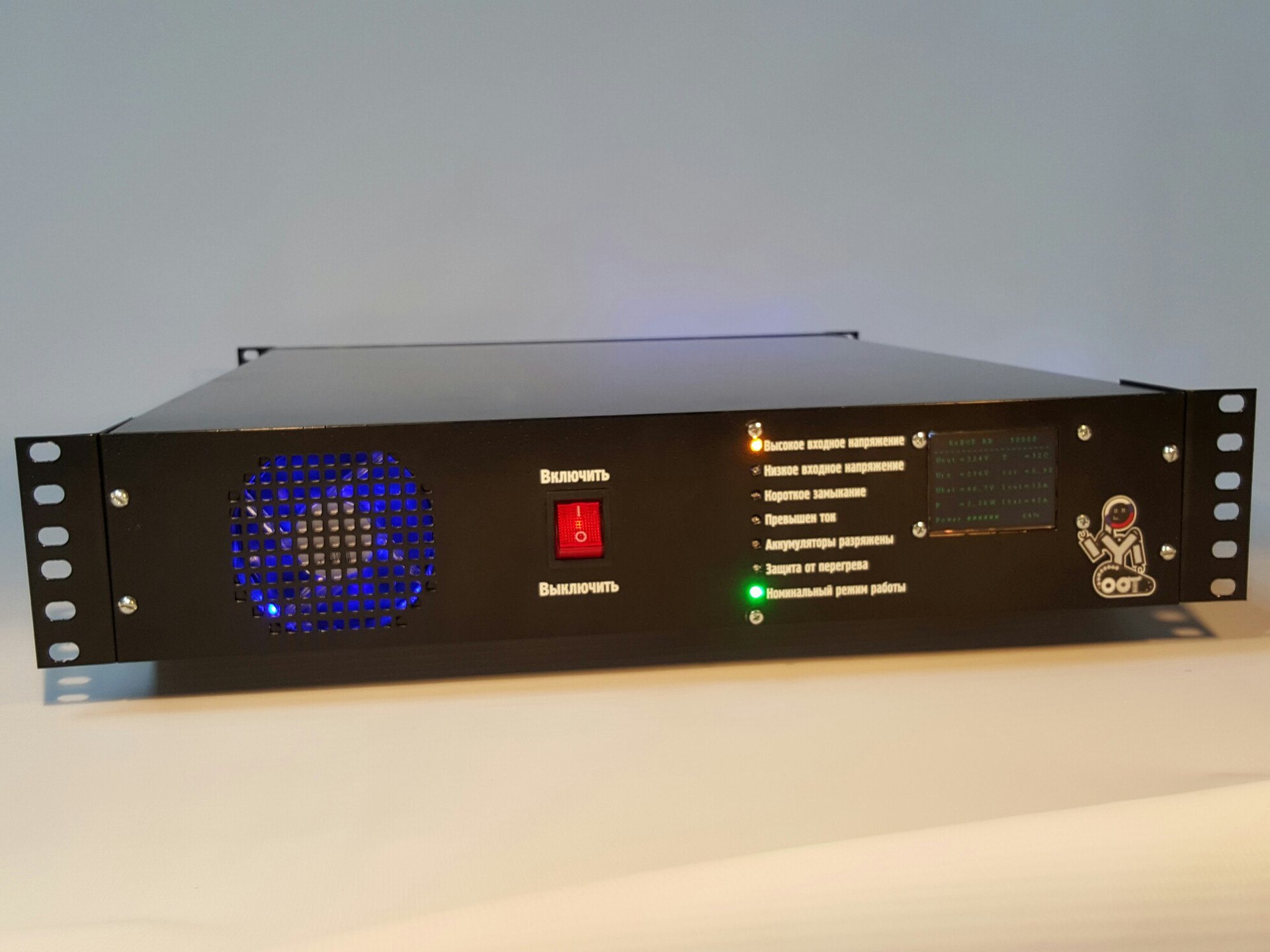
Figure 1 - View of the main panel of the UPS at 3200 W
Description: at the output you get exactly such a device and nothing else. Everything is done by hand and resorted to the production at a minimum. Our equipment was only manufactured body - standard for a server rack 2U and a depth of 600 mm.
On the panel there is a cooling cooler that works for air intake. It is also controlled by the "brain" based on STM32F103RBT6 using PWM with temperature feedback. That is, the value of turns depends on the temperature of the radiators of power switches and on the temperature of the transformer. Temperature measurement is implemented “in the old manner” on DS18B20, communicating via the 1-Wire interface.
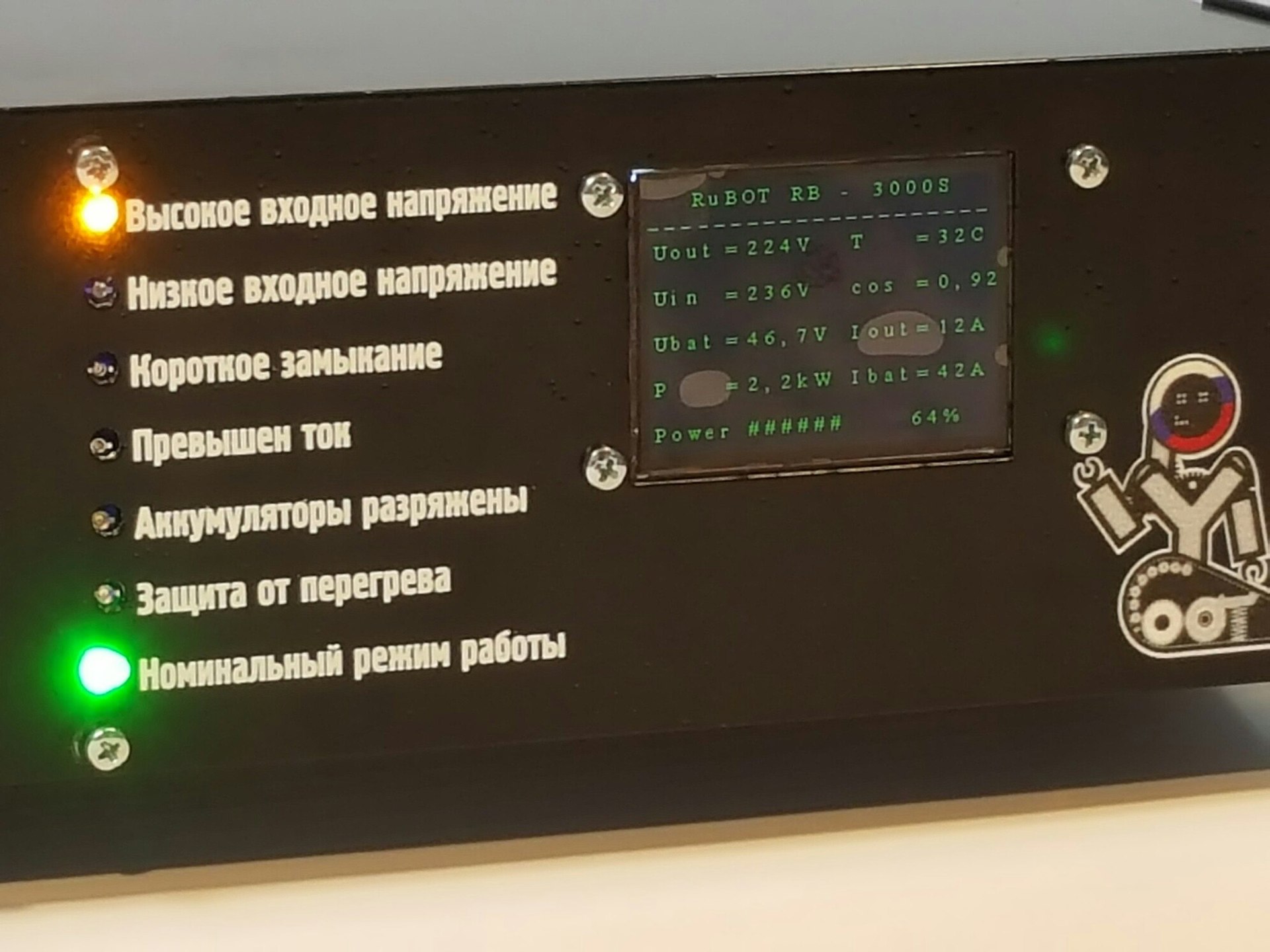
Figure 2 - View of the working panel with full parameters of the device
All data on the operation of the device is displayed on a 2.4 "TFT panel, working through the SPI interface through the ILI9341 controller built into the display. An LED scale has been added for a more visual display of the operating modes: " Red LED is on?
Now let's look a little from another angle on the device:
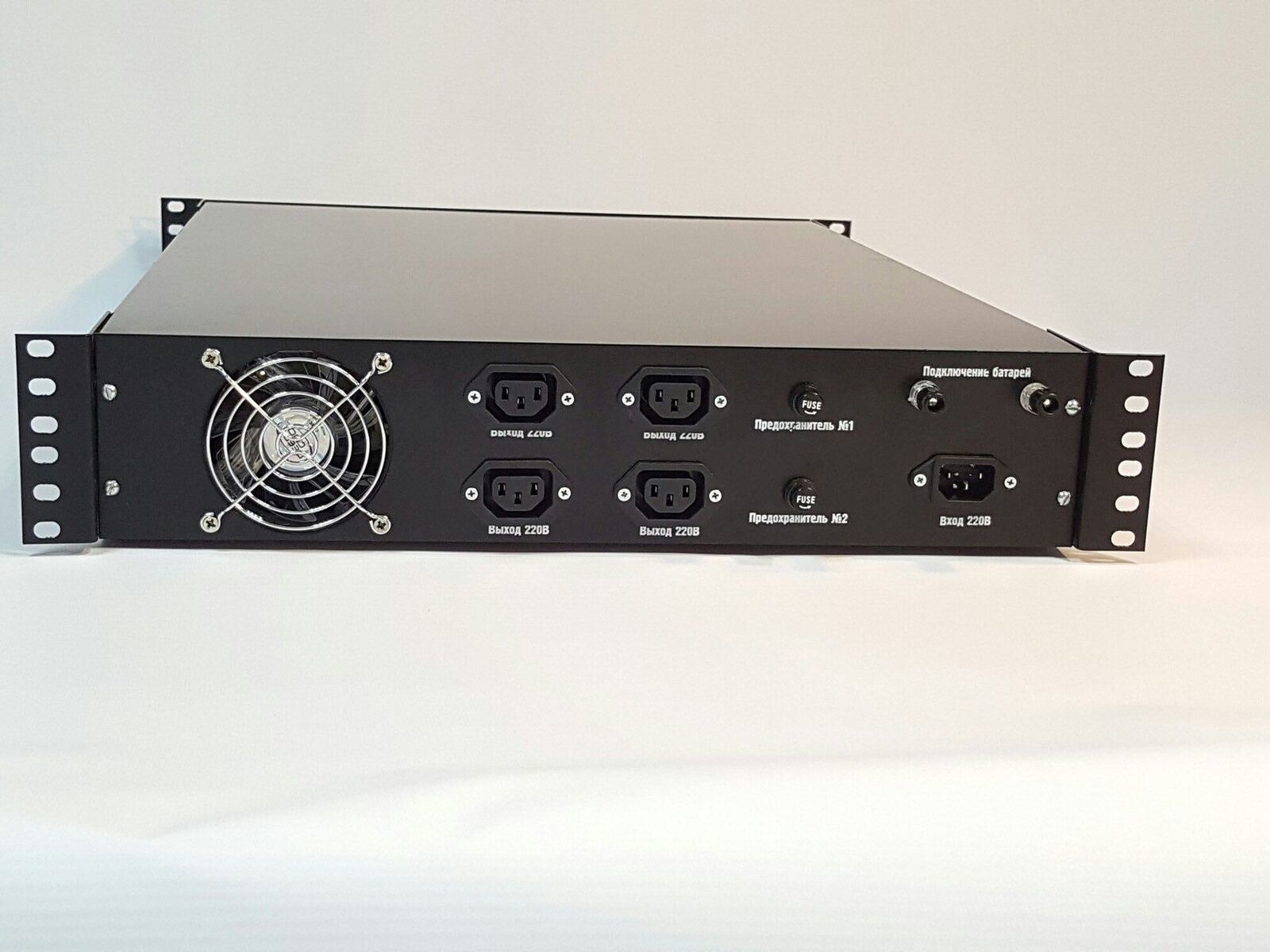
Figure 3 - View of the rear panel of the device
Description: on the rear panel everything is modest and functional: a connector for the input cable, 4 "sockets" for connecting the load, fuses for 25A, a terminal for connecting batteries with a limit (tested by me) current of 110A (manufacturer declared 150A).
Specifications specifications
First, a few notes to the general functionality. The first, like any on-line UPS, our device must perform the function of a voltage stabilizer. So come the top-end company Schneider Electric and I decided to learn from their experience, which is no secret. Now to the characteristics ... Required to get:
- rated power: 3200 W
- input voltage range: 85 - 265 V (this figure is stated by Schneider)
- output voltage: 230 V + - 3% (exactly 230, not 220. Standards have changed now)
- DC bus voltage: 48 V
- rated current of 230V: 16 A
- rated current on DC bus: 80 A
- starting currents: 650% of nominal
- overload capacity: 150% within 30 minutes, 200% within 12 minutes
- battery runtime: batteries are external and time depends on the number of batteries
- possibility of remote access to the device
- time between failures, not less: 120 000 hours
I think with the requirements placed on the device everything is clear, then we proceed to the stage of defining the design concept and the choice of topologies.
Design a block diagram of the device
Perhaps this is the most important design stage. Any mistake will result in a huge loss of time, resources and money, for this I advise you to treat this task very carefully and without haste.
Thoughts
1) It is necessary to choose the methods of switching circuits (switching). There are several methods / types and each has its own pros and cons. Consider the typical ones:
a) Mechanical is a method of switching circuits by means of electromechanical devices, most often a relay. Pros: simplicity. Cons: low reliability, long switching time (about 0.2 seconds while the relay is new), the possibility of sticking of the relay, which will cause the process of arc burning between the contacts. I think it is clear why this is not our method? We still focus on Schneider.
b) Electronic is a method of switching by means of NOT mechanical components: diodes, triacs, field effect transistors, thyristors. The options can be many, the most adequate in my opinion - the diode valve. Pros: simplicity, the absence of mechanical moving parts. Cons: additional heat loss. In our case, at 80A and a drop in the Schottky diodes of 0.5V, we will have to additionally dissipate about 180 W, and there are at least two such diodes. Losses in the form of 10% of KPD. I consider blasphemy, so the method is not ours again.
c) Complete failure of switching. Actually, why do we need it? I heard a bunch of cries against it, but
What is the essence of this - our batteries just hang in the buffer circuit on the DC bus and are constantly in the process of charge-discharge. It scares many people, but you try to lie down for a month on the sofa, and then be surprised that it is hard for you to climb the stairs. So it is with the battery - they need to be “trained” and therefore the buffer circuit is useful for them , provided that the current is very fast .
Pros: cheap, angry, reliable, the absence of the concept of "switching time" or "time of transition from mains power to batteries" and the absence of additional losses. Disadvantages: it is necessary to use only
2) It is necessary to choose a conversion scheme: HF vs LF
You can argue here endlessly and each one bends its own line. Many manufacturers call the conversion at frequencies of 10-150 kHz unreliable, but this is usually an elementary PR move with attempts to justify their inconsistency in the production of such equipment. I think if the technology was not the best choice, then the leading global companies would not have switched to it and would not have been engaged in its improvement over the past 20 years.
From the LF conversion bonuses at a frequency of 50 Hz, I can note the simplicity of production; the
Of the minuses ... there are a lot of them, but the main one is simply huge dimensions! Once they tried to make 1100 kW according to this scheme, and so there was 1.8 tons of copper alone! I think you can imagine all the scales.
The debate on the choice of technology will not develop, because even among my colleagues, he usually turned into a fight with a clear personality transition. Therefore, we simply choose the technology of conversion at high frequency (10-150 kHz).
Based on the arguments described above and a dozen others that will come out in the course of the project we will receive the following scheme:
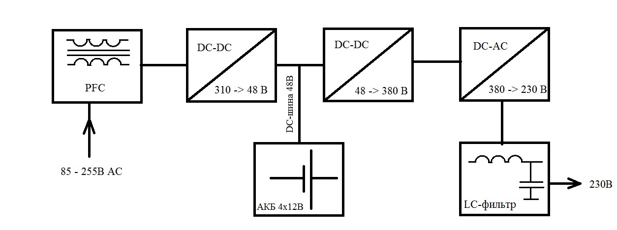
Figure 4 - Block diagram of the power section of the UPS double conversion
I will explain the displayed stages a little:
1) Almost immediately after the input voltage is applied to the PFC - it is the power corrector. It is needed primarily to reduce losses, so it is simply necessary. In Chinese schemes and most domestic ones, it is not provided at all, it reduces the cost, but the quality of the device can be safely "divided by 2".
Details of this parameter and the module will tell Google or me in the next part of the article. I can say one thing - get ready for a rather serious “matan” and remember Cauchy inequalities.
2) Next comes the first conversion - 85-255V AC to 48 V DC. Immediately please pay attention to a few points. Firstly, the input voltage range is very wide, it will create a problem - if the voltage is 3 times lower than the nominal (85V for example), then the current will increase by 3 times, therefore this feature ( Ohm's law ) must be kept in mind. This will force us further in the calculations of transformers and power IGBT keys to lay a minimum of three times the current margin.
Secondly, 48V is an approximate value for understanding. For the voltage on the battery in a charged state is 14.2 V, when connecting in series with 4 batteries, we get 56.8 V. It follows that the voltage on the DC bus will actually be about 57V - this is done so that it is applied to the battery the potential was higher than its own, then a potential difference would occur and a current would flow. The current “runs” in the direction of less potential, that is, on the battery. As soon as the potential in the DC bus is less than on batteries (for example, the mains voltage is gone) they begin to give energy (this is a reference to the switching method and why there is no switching process).
3) The battery sits on the DC bus in the buffer zone. Why 48V and why combine batteries? It's simple! The current when powered from 48 V is about 80 A, if powered from 12 V, then the current will be more than 300A! Huge value - huge losses. Yes, and the batteries, even gel, thanks for this mode of operation will not tell and will safely die in a year, instead of 10 years they are capable of.
4) Another DC-DC converter 48 -> 380 V. The principle of operation and circuitry will be in another part of the article, so far I will only explain why 380V, and not 310, which are obtained after rectifying the network. 380 V is necessary for us to calmly and without loss cut into a sinusoidal signal of excellent shape. When we start to disassemble this process, understand why such a stock.
5) LC-filter / circuit or 4th-order LPF. It is necessary that after cutting the sine using PWM to filter out all unnecessary harmonics, interference, noise and other debris and to receive our treasured clean signal at the output. It is designed for 1 kHz, which, at a modulation frequency of 75.8 kHz, makes it possible to get pulsations of no more than + - 3 V. This falls into our requirements for TK and therefore further increases the filter order, and therefore its dimensions, I simply do not see.
It remains to mention a few modules that I did not depict in the block diagram. Why? Yes, they simply do not affect the fundamental understanding of the work and structure of this device, and some are a separate "caste." What I forgot:
- control module, in fact, “brains” of all measurements and indication on STM32F100RBT6
- the module of the formation of pure sine, it is a separate board, but it is included in a large DC-AC unit
- standby power module that provides low-voltage power supply (+ 15V, + 5V, + 3.3V) on the popular 70 W TOP227
- emergency power module, which converts 48V with battery to the same +15, +5, + 3.3V.
Epilogue
Yes, I would not overload the reader with the flow of information - I plan to break the whole process of designing and self-manufacturing the UPS into at least 10 parts. And how do you want? This is a difficult and responsible business!
I plan on passing the whole part for each module described above, and also single out one little article as a guide on the choice of components and the search for favorable prices. Manufacture of transformers and chokes, their calculations and winding will also be considered separately. All these stages will be accompanied by a detailed photo report and video.
I hope you are intrigued, and perhaps someone has already become interesting, so read on ...
Calculation and manufacture of the "heart" of the IIP - pulse transformer.
Part 2
Part 3
Part 4.1
Part 4.2
Part 5
Part 6
Source: https://habr.com/ru/post/358316/
All Articles