Planar transformer: technology, calculations, cost
Not so long ago, I was approached by one company that needed to develop a line of LED drivers. I will not name the company name and TTX drivers, NDA did not sign, but ethics is ethics. It seems to be the usual order for the driver, which dozen for the year is recruited, but there were two mutually exclusive requirements: cost and size .
The task from the point of view of circuitry is simple, but from the point of view of production and design it turned out to be very interesting. And so - it was required to make a network driver for LED with a power factor corrector (power about 100 W), which cost $ 3 per lot and had dimensions of no more than 11 mm in height ! Many will say: “And what’s the problem with making a deshman driver?”, That's just not a deshmansky driver, since Another requirement is that it is possible to give without fear a 5 year warranty . And here begins the most interesting.
The choice of topology, circuitry was made, everything fit in size and cost, but such a wonderful picture was spoiled by a “classic” transformer. It is huge, it is expensive, it is technologically difficult to manufacture. It remained to solve the last problem and after two days in thought and calculations it was found - a planar transformer .
')
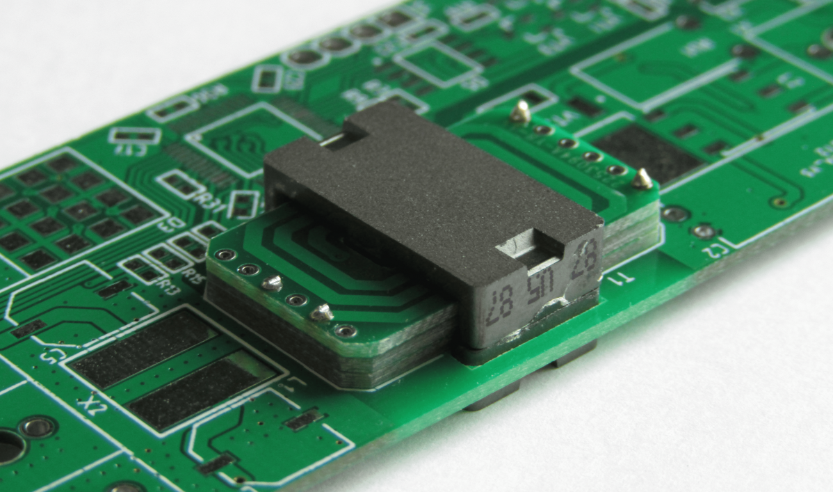
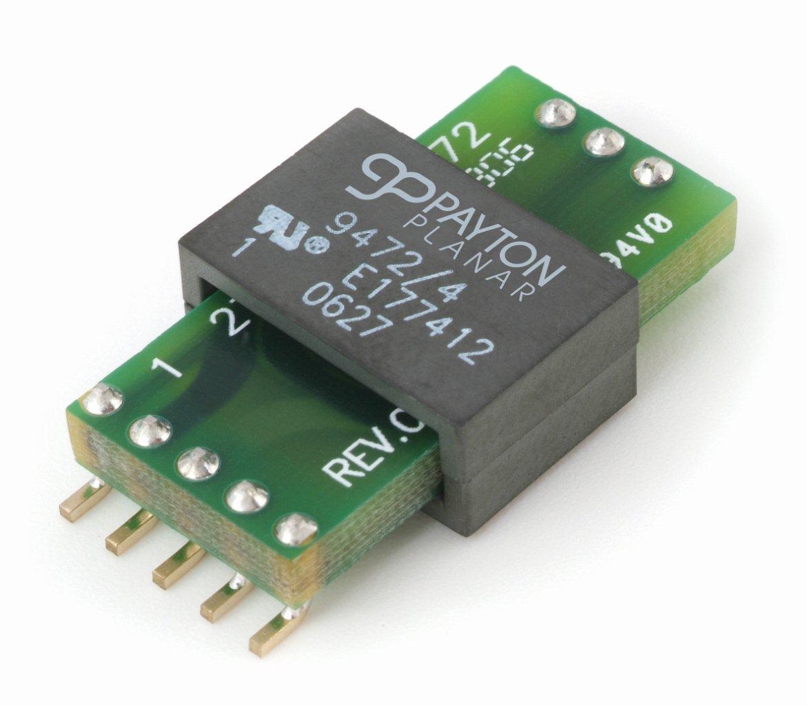
If you are interested in the choice between what and what, on which arguments it was based and how you managed to get the cost of the transformer less than $ 0.5, then I invite you to the tackle. Well, to improve the "appetite" I attach you a photo of the finished transformer:
I think it’s not a secret to anyone how an ordinary transformer looks like, but suddenly someone missed the last 150 years of the industrial revolution, so I remind you:
It looks like a normal transformer, wound on a frame from the core RM12. Why is he so bad? There are several reasons for this, of course, some of them lose their relevance in certain tasks, but the story will be conducted in the context of the task before me. And here are the main ones:
At this point, you are probably plagued by tormenting: “If everything is so bad, then why are ordinary transformers so common?” I said a little before that some of these disadvantages in certain tasks are not a minus. For example, if you open a UPS on-line, you will see that the transformer there is not the most dimensional element. And if you collect small batches of up to 100-200 devices per month, then surely the cost price will be equalized, because You can already make 100-200 pieces in Russia or hire a winder, buy a Chinese machine or make it yourself for 100-200 thousand rubles. and enjoy life.
And perhaps the main place where planar transformers do not supplant conventional ones - converters with a rated power greater than 2000 W.
In the very first picture you see this type of transformer already in the assembled state, the view is very unusual, is not it? Although people who opened up modern TVs, charging laptops (not cheap) have probably already seen such transformers or the like.
Planar transformers can be made in different designs, a clear classification does not exist as far as I know, but I divide them into 2 types:
Whatever type of planar transformer is considered, they have one thing in common - all windings are made in the form of copper tracks on a printed circuit board .
If you decide to familiarize yourself with this technology in more detail and go to Google, then surely in many articles you will find the phrase: "... and finally in recent years, planar transformers have become affordable. This is due to the fact that multilayer boards have become cheaper." When I designed my first planar transformer, the year so in 2010-11, this phrase confused me. I naively thought that planarniki do exclusively on multilayer printed circuit boards. At that time, I was still studying at a university, and although I worked and received a decent stipend, this type of board was not very affordable for me. I thought and decided tomake my Facebook !!!! reduce the cost of this technology, as it turned out later - invented a bicycle.
The essence of the reduction was the use of a “cake” of several two-layer printed circuit boards of small thickness (0.8 or 1 mm). For me, it seemed ingenious and simple solutions. But the problem was that, as always, I looked at the solutions of top companies dealing with power electronics, such as Texas Instruments, Linear, Infineon, Murata, and they used printed circuit boards in 6-8 layers and in 2010 they even standard 4 class (0.15 / 0.15 mm) were very expensive. Then it turned out that during the summer practice I was called into one good company and they told me there and showed that they have been doing these “pies” for planar transformers for 10 years already. Other companies also ranked lower than TI and Infineon. The main thing is that the idea was correct and this solution was not just the right one, but also a time-tested one .
All the elements of the “cake” are ordinary double-layer boards of standard accuracy class, which means they are soooo cheap and any manufacturer of printed circuit boards can make them. The elements of the “pie” of a planar transformer look like this:
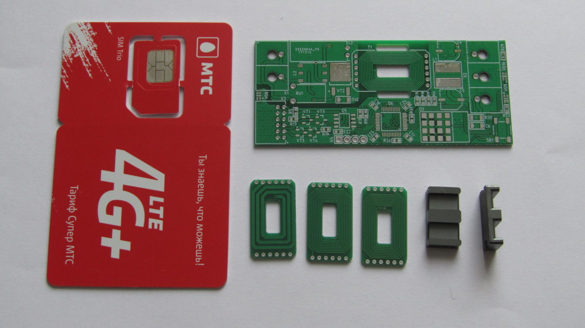
As you can see there are only 3 elements in my transformer, although it could have been more. Why 3? According to my calculations, in order to gain the required inductance in the primary winding, I would need 6 layers. 2 layers gives me the main board + 2 layers “piece of cake” + 2 layers “piece of cake”. The secondary winding fit only 2 layers, from here another "piece of cake." As a result, has a stack of 4 dual-layer printed circuit boards. Further arithmetic is even simpler: I use the core ELP18 / 4/10, which means that the distance under the “winding” is 4 mm. We divide this distance by the number of boards: 4 mm / 4 boards = 1 mm - the thickness of each printed circuit board. It's simple!
If you suddenly do not understand where the 4 mm gap came from, you can look at the datasheet on the core here . And for those who are not comfortable to follow the links or traffic do not want to spend on a large pdf-ku, a small clipping:
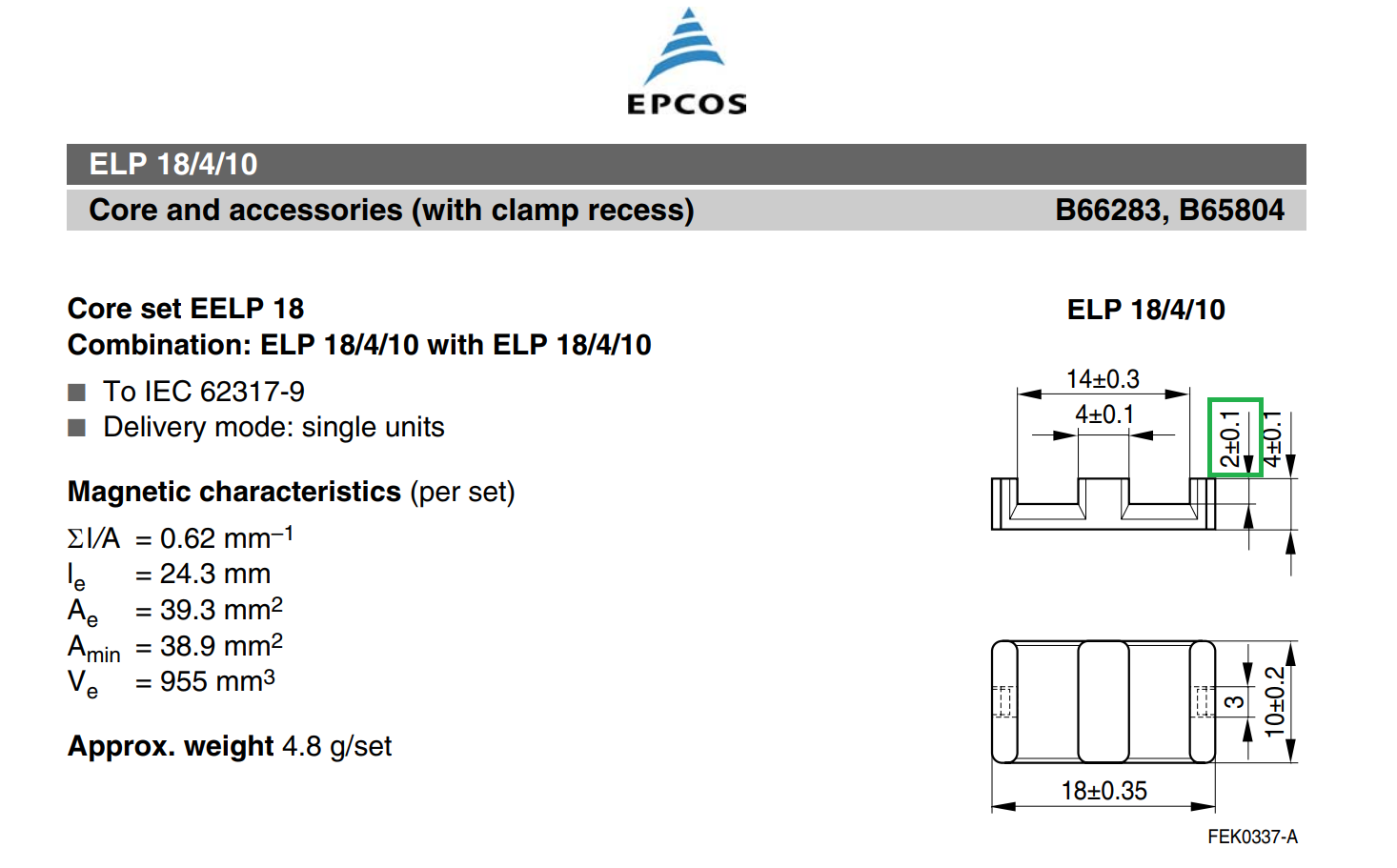
As you can see the size of the core window in one half is 2 mm, in the second half it is also 2 mm. We get the total size of the window in height - 4 mm.
Now it is possible to disassemble what the cost price of a planar transformer consists of. In fact, there are only 2 components: a core and 3 printed circuit boards. The core in bulk costs $ 0.14, printed circuit boards 3 pieces of $ 0.11 for each also on the series. We get $ 0.47 worth of the transformer itself. I did not include a compound for gluing the cores here, because if you scatter its cost for the entire batch, then even 1 cent does not work there and did not consider the assembly work. The work is not considered for one simple reason - the transformer is assembled at the stage of manual installation, but it costs a penny in Asia. For comparisons, soldering 2 transistors in the TO-220 package costs the same as installing a planar transformer, that is, again a miser comes out. That's how we get the figure of $ 0.5 for 1 transformer up to 100 watts .
A little about my results ... I managed to fit in the overall height and even did better - instead of the 11 mm limit, I got 9.6 mm. On the one hand, it is not very noticeable, but in practice this reduction in size is approximately 13%. With that, the main envelope in height asked no longer a transformer, but electrolytic SMD capacitors at the input and output.
At cost price - I can’t give you the exact figure, but it turned out to be in demand. It is worth noting the efforts of the customer himself, he managed to find suppliers who, on a large series, were able to give prices at a level, and sometimes slightly lower than at a digikey. Personally, my merit is that I solved a technical task and did it cheaply, and the customer himself has already done super-cheap without loss of quality.
Then my article takes more technical character than the narrative, and if you are not interested in power electronics, dry calculations and other bad things, then you can stop reading and proceed to the discussion in the comments. Beautiful pictures will no longer be. If you plan to adopt this technology for yourself, then everything is just beginning for you.
Planar transformers, due to their physical and constructive properties, allow us to get not only a gain in terms of manufacturability, and accordingly cost, but also open up new horizons for us in the design. Let's look at the main advantages that we get when using planar transformers:
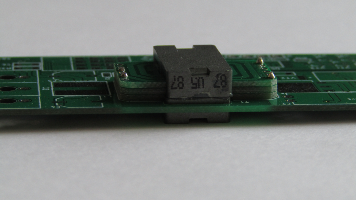
So that you can more clearly evaluate the full potential of this type of transformers, I can say that in this project, on one pair of ELP18 / 4/10 cores, I managed to build a 65 W resonant converter. And now look at its overall dimensions, is it not bad for such a trifle?
Techniques that allow you to calculate this type of transformer, quite a lot. True basic literature, including scientific, mainly in English, German and Chinese. I tried several in practice, all of them were taken from English-speaking sources and all showed an acceptable result. In the course of work, over the course of several years, I made minor edits that made it possible to somewhat increase the accuracy of the calculations, and I will demonstrate this technique to you.
I do not have any ambitions for its uniqueness, and I also do not guarantee that its results are sufficiently accurate in all frequency and power ranges. Therefore, if you plan to use in your work, be careful and always monitor the adequacy of the results.
A little bit about modeling ... You can, and sometimes you need to do it, but working even with a monster like Comsol, I could not get more accuracy than the usual methods described everywhere. I tried to take into account a greater number of parasitic parameters, and more accurately describe the skin effect, and to take into account magnetic changes in the core material and much more - accuracy was better than + -3-5% could not be obtained. Therefore, I don’t see any sense at the capacities up to 150–200 W (of course, you can disagree), but after 200 W you cannot do without it, especially if you have a resonant transducer.
When calculating any transformer, the first thing you need to find the maximum value of magnetic induction. Losses in the core and in copper conductors lead to the heating of the transformer, therefore, calculations must be made with respect to the maximum allowable overheating of the transformer. The latter is selected on the basis of operating conditions and requirements for the device.
To cases, an empirical assumption in which we assume that half of the total losses on a transformer is core loss. Based on this assumption, we calculate the maximum density of losses in the core according to the empirical formula:
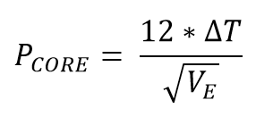
Where the value of the effective magnetic volume V E is taken from the documentation on the core in [cm 3 ] , the value of the maximum superheat ΔT is selected on the basis of calculations (for example, I usually take into account 50-60 degrees ). The dimension of the obtained value is [mW / cm 3 ] .
Now, knowing the maximum density of losses in the core, we can calculate the maximum value of inductance at which the superheat temperature will not be exceeded above the calculated one.

Where M , T , x , y are the parameters obtained empirically by the method of approximation of the loss curve, and f is the conversion frequency. You can get them in two ways: by processing the data (graphs) from the documentation on your core or by building these graphs yourself. The latter method will allow you to obtain more accurate data, but you will need a full-fledged thermal imager.
As an example, I will share with you these values for cores of Epcos N49 material, its counterpart from Ferrocube is also the popular and affordable material 3F3 . Both materials allow you to easily build converters with a resonant frequency up to 1 MHz inclusive. It is also worth noting that these parameters depend on the frequency, these figures are for frequencies 400-600 kHz . This is the most popular frequency range and material that I use.
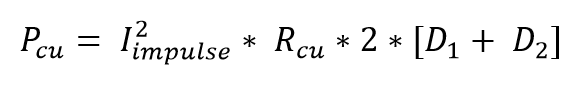
Further, it is worth recalling the second component of losses in the transformer - losses in the copper winding . They are considered easy, according to our favorite Ohm's law, which additionally took into account quite logical moments: the current is pulsed and it flows not 100% of the time, that is, the fill factor. I will not tell how to calculate the resistance of the copper winding according to its geometry, it’s too trite, and I’d like to remind you of the general formula:
Copper losses are counted separately for each winding, and then added. Now we know the losses in each layer of the “pie” and in the core. Those interested can simulate transformer overheating, for example, in Comsol or Solidworks Flow Simulation.
Continuing the theme of copper conductors, let us recall the phenomenon of the skin effect . If explained “on the fingers”, this is an effect when, with an increase in the frequency of the current flowing in the conductor, the current is “squeezed out” of the conductor (from the center to the surface) by another current, vortex .
Speaking more scientifically, as a result of alternating current flowing through the conductor, variable induction is induced, which in turn causes eddy currents. These eddy currents have a direction opposite to our main current and it turns out that they mutually calculate and the total current in the center of the conductor is zero.
The logic is simple - the higher the frequency of the current flow, the greater the effect of the skin effect and the lower the effective conductor cross section . Its influence can be reduced by optimizing the geometry of the windings, their parallelization and other methods that probably deserve, if not a whole book, then a large separate article.
For our calculations, it is sufficient to roughly estimate the effect of the skin effect using another empirical formula:
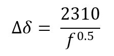
Where ∆δ is the thickness of the zone with zero current, f is the frequency of the converter in [kHz] . As you can see this effect is entirely tied to the switching frequency.
And now let's calculate how many turns and other things we need to make a forward running transformer. First of all, we consider how many turns we need in the primary winding:
Where U min is the minimum input voltage, D is the duty cycle, f is the frequency of operation, A e is the effective cross section of the core. Now we count the number of turns for the second winding:
Where N 1 is the number of turns in the primary winding, D is the duty cycle, U out is the nominal output voltage, U min is the minimum input voltage.
The next step is to calculate the inductance of the primary winding. Since the current in the winding we have impulse response, it will also depend on the inductance. We calculate it according to the following formula:
Where μ 0 is the effective magnetic permeability, μ a is the amplitude magnetic permeability, A e is the effective cross section of the core, N 1 is the number of turns in the primary winding, I e is the effective path length. Missing parameters, such as permeability and magnetic line length, can be found in the documentation for a specific core.
Now the final step that we need to take is to calculate the current in the primary winding. This will allow to calculate the cross section for the primary winding and, accordingly, the width of the conductor. The current value consists of two components and looks as follows:
Here, it seems, all the constituent formulas are familiar and calculated, the only thing I will note is the P max parameter. This is not just the value of the nominal output power, it is the total power of the converter, taking into account the efficiency at least approximately (I usually lay 95-97% for resonant converters) and the margin that you are laying into the device. In my devices, usually 10% power reserve, in especially important devices and nodes sometimes you have to lay 20-25% margin, but this causes a rise in price.
So we got all the parameters that are necessary for the calculation and design of a planar transformer. Of course, you will have to calculate the cross section for the windings yourself, but this is an elementary arithmetic that I don’t want to overload the article with. All the rest is already calculated and it remains only to design the board in any CAD system.
I hope my article will help you begin to use planar transformers in your home projects, as well as in commercial ones. This technology should be used carefully, because depending on the task, it may be more expensive than “classic” transformers.
The use of planar transformers undoubtedly opens up new technical capabilities, and modern Mosfet-s and new GaN transistors only contribute to this, allowing you to create converters with frequencies from 400 kHz and above. However, the cost of these “capabilities” is not always low enough, and for designing resonant transducers at such frequencies requires a large set of knowledge and experience.
But do not be upset! Any of you, even a beginner electronics engineer, is able to assemble topologies for simpler, for example, ZVS bridge (Full bridge). This topology allows you to get a very high efficiency and does not require some kind of super-secret knowledge. It is only necessary to make a prototype or a layout and experiment carefully. Good luck in mastering new horizons!
The task from the point of view of circuitry is simple, but from the point of view of production and design it turned out to be very interesting. And so - it was required to make a network driver for LED with a power factor corrector (power about 100 W), which cost $ 3 per lot and had dimensions of no more than 11 mm in height ! Many will say: “And what’s the problem with making a deshman driver?”, That's just not a deshmansky driver, since Another requirement is that it is possible to give without fear a 5 year warranty . And here begins the most interesting.
The choice of topology, circuitry was made, everything fit in size and cost, but such a wonderful picture was spoiled by a “classic” transformer. It is huge, it is expensive, it is technologically difficult to manufacture. It remained to solve the last problem and after two days in thought and calculations it was found - a planar transformer .
')
If you are interested in the choice between what and what, on which arguments it was based and how you managed to get the cost of the transformer less than $ 0.5, then I invite you to the tackle. Well, to improve the "appetite" I attach you a photo of the finished transformer:
The main disadvantages of "classic" transformers
I think it’s not a secret to anyone how an ordinary transformer looks like, but suddenly someone missed the last 150 years of the industrial revolution, so I remind you:
It looks like a normal transformer, wound on a frame from the core RM12. Why is he so bad? There are several reasons for this, of course, some of them lose their relevance in certain tasks, but the story will be conducted in the context of the task before me. And here are the main ones:
- Height. Even a person with a bad eye can roughly estimate the size of a transformer from a photo and say with confidence: "It is definitely more than 11 mm." Indeed, the transformer height on RM12 is about 24 mm, which is more than 2 times the required value.
- Manufacturability. When you need to wind 1-2 transformers, then you take the frame, the wire and shake. When you need to wind 100-200 pieces, you can order the winding in your own country, the price does not bite yet. When you need to wind 10,000 pieces, and then another 50,000, then a lot of nuances arise: price, quality, and the choice of another contractor in Asia. All this increases the final cost of the product, when I need just super cheap and very high quality.
- Repeatability. It is very difficult to wind and assemble two identical transformers, it is impossible to make 10,000 identical transformers. This I have experienced the hard way more than once, especially when it comes to production in SA. Now imagine
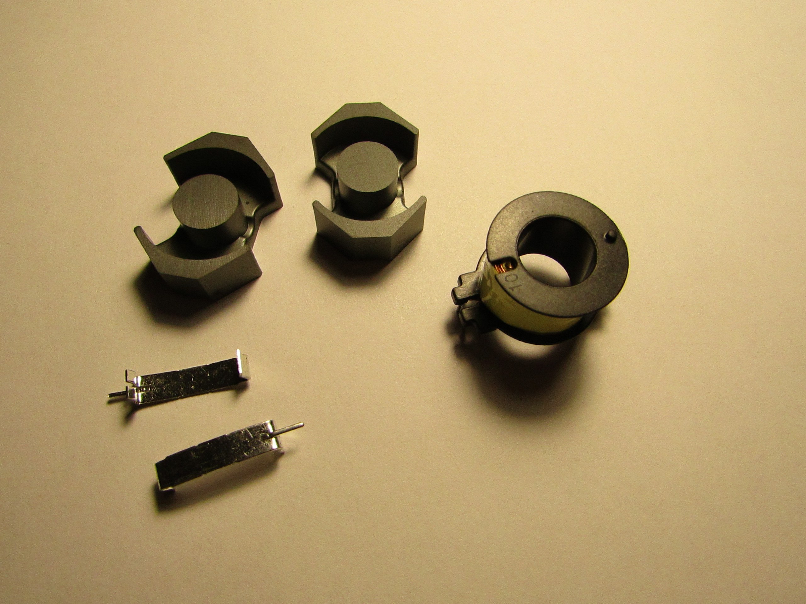
that you will have to “refine” a file of these 10,000 transformers during the final assembly. Submitted? You feel sad about the amount of effort, and therefore cost? I think it has become. - Cost price. This is generally a very difficult point, but let's look at the photo above and see that to assemble a classic transformer, we need a frame, core, brackets, copper wire, insulation, and all this with our hands or on a semi-automatic machine. Let's say it all costs "X dollars." For the manufacture of a planar transformer only a core is needed. I think it’s obvious here that 1 part is clearly cheaper than 1 is the same part + 4 more components?
At this point, you are probably plagued by tormenting: “If everything is so bad, then why are ordinary transformers so common?” I said a little before that some of these disadvantages in certain tasks are not a minus. For example, if you open a UPS on-line, you will see that the transformer there is not the most dimensional element. And if you collect small batches of up to 100-200 devices per month, then surely the cost price will be equalized, because You can already make 100-200 pieces in Russia or hire a winder, buy a Chinese machine or make it yourself for 100-200 thousand rubles. and enjoy life.
And perhaps the main place where planar transformers do not supplant conventional ones - converters with a rated power greater than 2000 W.
Planar Transformer Device
In the very first picture you see this type of transformer already in the assembled state, the view is very unusual, is not it? Although people who opened up modern TVs, charging laptops (not cheap) have probably already seen such transformers or the like.
Planar transformers can be made in different designs, a clear classification does not exist as far as I know, but I divide them into 2 types:
- Independent. The transformer is a separate electronic component that can be separately supplied and manufactured. This solution is good in the presence of a large range of devices, where the transformer is unified. This is not my case. I have to cheap, and unification always requires sacrifice in the form of a small appreciation.
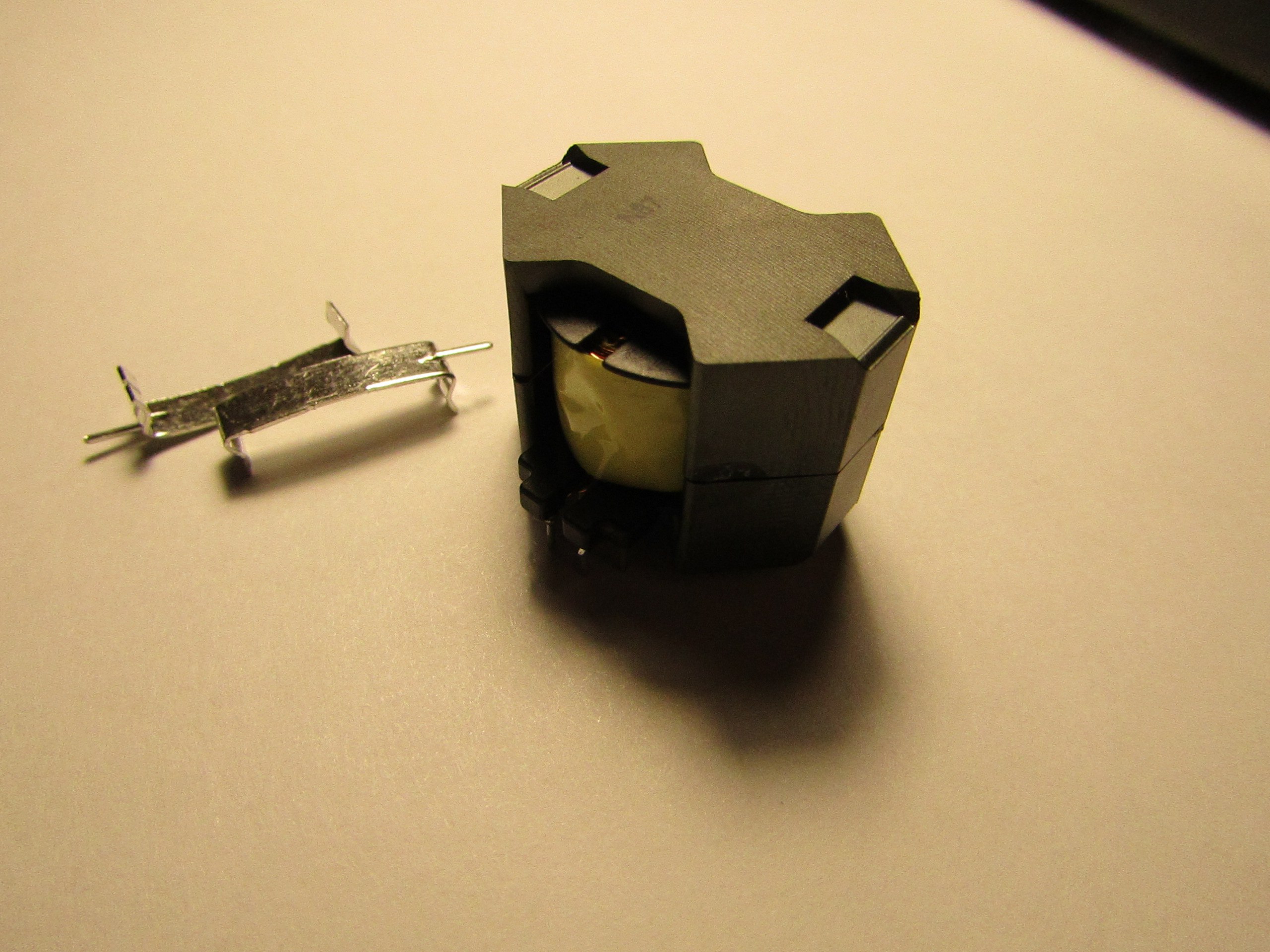
- With a common core. This is just my case. With this design, the transformer windings are made on the main printed circuit board of the device and are not its integral part. The core is simply put on the board and fastened with staples or otherwise, for example, with glue or compound.
Whatever type of planar transformer is considered, they have one thing in common - all windings are made in the form of copper tracks on a printed circuit board .
If you decide to familiarize yourself with this technology in more detail and go to Google, then surely in many articles you will find the phrase: "... and finally in recent years, planar transformers have become affordable. This is due to the fact that multilayer boards have become cheaper." When I designed my first planar transformer, the year so in 2010-11, this phrase confused me. I naively thought that planarniki do exclusively on multilayer printed circuit boards. At that time, I was still studying at a university, and although I worked and received a decent stipend, this type of board was not very affordable for me. I thought and decided to
The essence of the reduction was the use of a “cake” of several two-layer printed circuit boards of small thickness (0.8 or 1 mm). For me, it seemed ingenious and simple solutions. But the problem was that, as always, I looked at the solutions of top companies dealing with power electronics, such as Texas Instruments, Linear, Infineon, Murata, and they used printed circuit boards in 6-8 layers and in 2010 they even standard 4 class (0.15 / 0.15 mm) were very expensive. Then it turned out that during the summer practice I was called into one good company and they told me there and showed that they have been doing these “pies” for planar transformers for 10 years already. Other companies also ranked lower than TI and Infineon. The main thing is that the idea was correct and this solution was not just the right one, but also a time-tested one .
All the elements of the “cake” are ordinary double-layer boards of standard accuracy class, which means they are soooo cheap and any manufacturer of printed circuit boards can make them. The elements of the “pie” of a planar transformer look like this:
As you can see there are only 3 elements in my transformer, although it could have been more. Why 3? According to my calculations, in order to gain the required inductance in the primary winding, I would need 6 layers. 2 layers gives me the main board + 2 layers “piece of cake” + 2 layers “piece of cake”. The secondary winding fit only 2 layers, from here another "piece of cake." As a result, has a stack of 4 dual-layer printed circuit boards. Further arithmetic is even simpler: I use the core ELP18 / 4/10, which means that the distance under the “winding” is 4 mm. We divide this distance by the number of boards: 4 mm / 4 boards = 1 mm - the thickness of each printed circuit board. It's simple!
If you suddenly do not understand where the 4 mm gap came from, you can look at the datasheet on the core here . And for those who are not comfortable to follow the links or traffic do not want to spend on a large pdf-ku, a small clipping:
As you can see the size of the core window in one half is 2 mm, in the second half it is also 2 mm. We get the total size of the window in height - 4 mm.
Now it is possible to disassemble what the cost price of a planar transformer consists of. In fact, there are only 2 components: a core and 3 printed circuit boards. The core in bulk costs $ 0.14, printed circuit boards 3 pieces of $ 0.11 for each also on the series. We get $ 0.47 worth of the transformer itself. I did not include a compound for gluing the cores here, because if you scatter its cost for the entire batch, then even 1 cent does not work there and did not consider the assembly work. The work is not considered for one simple reason - the transformer is assembled at the stage of manual installation, but it costs a penny in Asia. For comparisons, soldering 2 transistors in the TO-220 package costs the same as installing a planar transformer, that is, again a miser comes out. That's how we get the figure of $ 0.5 for 1 transformer up to 100 watts .
A little about my results ... I managed to fit in the overall height and even did better - instead of the 11 mm limit, I got 9.6 mm. On the one hand, it is not very noticeable, but in practice this reduction in size is approximately 13%. With that, the main envelope in height asked no longer a transformer, but electrolytic SMD capacitors at the input and output.
At cost price - I can’t give you the exact figure, but it turned out to be in demand. It is worth noting the efforts of the customer himself, he managed to find suppliers who, on a large series, were able to give prices at a level, and sometimes slightly lower than at a digikey. Personally, my merit is that I solved a technical task and did it cheaply, and the customer himself has already done super-cheap without loss of quality.
Technical capabilities opened by a planar transformer
Then my article takes more technical character than the narrative, and if you are not interested in power electronics, dry calculations and other bad things, then you can stop reading and proceed to the discussion in the comments. Beautiful pictures will no longer be. If you plan to adopt this technology for yourself, then everything is just beginning for you.
Planar transformers, due to their physical and constructive properties, allow us to get not only a gain in terms of manufacturability, and accordingly cost, but also open up new horizons for us in the design. Let's look at the main advantages that we get when using planar transformers:
- Low thermal resistance. It is due to the higher ratio of the surface area of the core to its volume. Due to this, the cooling capacity of planar transformers is significantly higher compared with the "classical" transformers by 50-70% . This allows us to design a greater current density during the design, and therefore provide a higher energy density with the same effective core volume (V e ). At the same time, the temperature rise remains within acceptable limits.
- High current density. The increased current density is a consequence of the previous “plus” planar transformer. Usually for a transformer with a wire winding, the standard value of current density is about 6-7-8 A / mm 2 , when for a planar transformer it is about 15-25A / mm 2 . This, of course, other things being equal, such as the superheat temperature
- Excellent repeatability of parasitic parameters. The geometry of printed circuit boards during production is maintained very precisely, which provides almost perfect repeatability of parasitic parameters. This makes it quite easy to design resonant converters, for example, LLC half-bridge and achieve very high switching frequencies up to 2-4 MHz
- High coupling coefficient. Everything is simple - less winding losses,
which means higher efficiency of the converter we get - Low leakage inductance. Due to this, the amplitude of EMF emissions and voltage fluctuations below, which in turn increases the reliability of transistors
- Very high energy density. Due to the combination of all the previously described properties of the planar transformer.
So that you can more clearly evaluate the full potential of this type of transformers, I can say that in this project, on one pair of ELP18 / 4/10 cores, I managed to build a 65 W resonant converter. And now look at its overall dimensions, is it not bad for such a trifle?
Method for calculating planar transformer
Techniques that allow you to calculate this type of transformer, quite a lot. True basic literature, including scientific, mainly in English, German and Chinese. I tried several in practice, all of them were taken from English-speaking sources and all showed an acceptable result. In the course of work, over the course of several years, I made minor edits that made it possible to somewhat increase the accuracy of the calculations, and I will demonstrate this technique to you.
I do not have any ambitions for its uniqueness, and I also do not guarantee that its results are sufficiently accurate in all frequency and power ranges. Therefore, if you plan to use in your work, be careful and always monitor the adequacy of the results.
A little bit about modeling ... You can, and sometimes you need to do it, but working even with a monster like Comsol, I could not get more accuracy than the usual methods described everywhere. I tried to take into account a greater number of parasitic parameters, and more accurately describe the skin effect, and to take into account magnetic changes in the core material and much more - accuracy was better than + -3-5% could not be obtained. Therefore, I don’t see any sense at the capacities up to 150–200 W (of course, you can disagree), but after 200 W you cannot do without it, especially if you have a resonant transducer.
Calculation of planar transformer
When calculating any transformer, the first thing you need to find the maximum value of magnetic induction. Losses in the core and in copper conductors lead to the heating of the transformer, therefore, calculations must be made with respect to the maximum allowable overheating of the transformer. The latter is selected on the basis of operating conditions and requirements for the device.
To cases, an empirical assumption in which we assume that half of the total losses on a transformer is core loss. Based on this assumption, we calculate the maximum density of losses in the core according to the empirical formula:
Where the value of the effective magnetic volume V E is taken from the documentation on the core in [cm 3 ] , the value of the maximum superheat ΔT is selected on the basis of calculations (for example, I usually take into account 50-60 degrees ). The dimension of the obtained value is [mW / cm 3 ] .
Please note that many of the formulas that I describe are obtained empirically. Others are written in their final form without listing their mathematical inference. For those who are interested in the origin of the latter, I advise you simply to acquaint you with foreign literature on magnetic materials, for example, there are books by Epcos and Ferroxcube.
Now, knowing the maximum density of losses in the core, we can calculate the maximum value of inductance at which the superheat temperature will not be exceeded above the calculated one.
Where M , T , x , y are the parameters obtained empirically by the method of approximation of the loss curve, and f is the conversion frequency. You can get them in two ways: by processing the data (graphs) from the documentation on your core or by building these graphs yourself. The latter method will allow you to obtain more accurate data, but you will need a full-fledged thermal imager.
As an example, I will share with you these values for cores of Epcos N49 material, its counterpart from Ferrocube is also the popular and affordable material 3F3 . Both materials allow you to easily build converters with a resonant frequency up to 1 MHz inclusive. It is also worth noting that these parameters depend on the frequency, these figures are for frequencies 400-600 kHz . This is the most popular frequency range and material that I use.
- C M = 4.1 * 10 -5
- With T = 1.08 * 10 -2
- x = 1.96
- y = 2.27
Further, it is worth recalling the second component of losses in the transformer - losses in the copper winding . They are considered easy, according to our favorite Ohm's law, which additionally took into account quite logical moments: the current is pulsed and it flows not 100% of the time, that is, the fill factor. I will not tell how to calculate the resistance of the copper winding according to its geometry, it’s too trite, and I’d like to remind you of the general formula:
Copper losses are counted separately for each winding, and then added. Now we know the losses in each layer of the “pie” and in the core. Those interested can simulate transformer overheating, for example, in Comsol or Solidworks Flow Simulation.
Continuing the theme of copper conductors, let us recall the phenomenon of the skin effect . If explained “on the fingers”, this is an effect when, with an increase in the frequency of the current flowing in the conductor, the current is “squeezed out” of the conductor (from the center to the surface) by another current, vortex .
Speaking more scientifically, as a result of alternating current flowing through the conductor, variable induction is induced, which in turn causes eddy currents. These eddy currents have a direction opposite to our main current and it turns out that they mutually calculate and the total current in the center of the conductor is zero.
The logic is simple - the higher the frequency of the current flow, the greater the effect of the skin effect and the lower the effective conductor cross section . Its influence can be reduced by optimizing the geometry of the windings, their parallelization and other methods that probably deserve, if not a whole book, then a large separate article.
For our calculations, it is sufficient to roughly estimate the effect of the skin effect using another empirical formula:
Where ∆δ is the thickness of the zone with zero current, f is the frequency of the converter in [kHz] . As you can see this effect is entirely tied to the switching frequency.
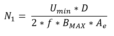
And now let's calculate how many turns and other things we need to make a forward running transformer. First of all, we consider how many turns we need in the primary winding:
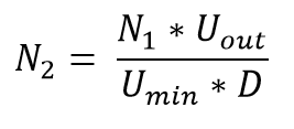
Where U min is the minimum input voltage, D is the duty cycle, f is the frequency of operation, A e is the effective cross section of the core. Now we count the number of turns for the second winding:
Where N 1 is the number of turns in the primary winding, D is the duty cycle, U out is the nominal output voltage, U min is the minimum input voltage.
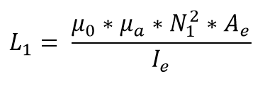
The next step is to calculate the inductance of the primary winding. Since the current in the winding we have impulse response, it will also depend on the inductance. We calculate it according to the following formula:
Where μ 0 is the effective magnetic permeability, μ a is the amplitude magnetic permeability, A e is the effective cross section of the core, N 1 is the number of turns in the primary winding, I e is the effective path length. Missing parameters, such as permeability and magnetic line length, can be found in the documentation for a specific core.
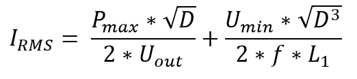
Now the final step that we need to take is to calculate the current in the primary winding. This will allow to calculate the cross section for the primary winding and, accordingly, the width of the conductor. The current value consists of two components and looks as follows:
Here, it seems, all the constituent formulas are familiar and calculated, the only thing I will note is the P max parameter. This is not just the value of the nominal output power, it is the total power of the converter, taking into account the efficiency at least approximately (I usually lay 95-97% for resonant converters) and the margin that you are laying into the device. In my devices, usually 10% power reserve, in especially important devices and nodes sometimes you have to lay 20-25% margin, but this causes a rise in price.
So we got all the parameters that are necessary for the calculation and design of a planar transformer. Of course, you will have to calculate the cross section for the windings yourself, but this is an elementary arithmetic that I don’t want to overload the article with. All the rest is already calculated and it remains only to design the board in any CAD system.
Total
I hope my article will help you begin to use planar transformers in your home projects, as well as in commercial ones. This technology should be used carefully, because depending on the task, it may be more expensive than “classic” transformers.
The use of planar transformers undoubtedly opens up new technical capabilities, and modern Mosfet-s and new GaN transistors only contribute to this, allowing you to create converters with frequencies from 400 kHz and above. However, the cost of these “capabilities” is not always low enough, and for designing resonant transducers at such frequencies requires a large set of knowledge and experience.
But do not be upset! Any of you, even a beginner electronics engineer, is able to assemble topologies for simpler, for example, ZVS bridge (Full bridge). This topology allows you to get a very high efficiency and does not require some kind of super-secret knowledge. It is only necessary to make a prototype or a layout and experiment carefully. Good luck in mastering new horizons!
Source: https://habr.com/ru/post/358174/
All Articles