ACS, raspberry and kettle
 The main actors are listed in the header, and as a result we will get a prototype of a simple access control system based on exactly the same RFID module RC522 , which can be used not only to open the door, but also to perform any similar action by applying and stopping the control signal.
In the presence of a lot of diverse information on the Internet with not quite working examples, I will try to describe everything step by step and in detail. This module works with RFID cards at a frequency of 13.56 MHz and, in addition to cards and chips with such a frequency, it also easily understands Moscow single tickets (I used the one-time single ticket used) and NFC tags.
Hardware
To implement the project, you need to connect the module and several additional components.
Module wiring diagram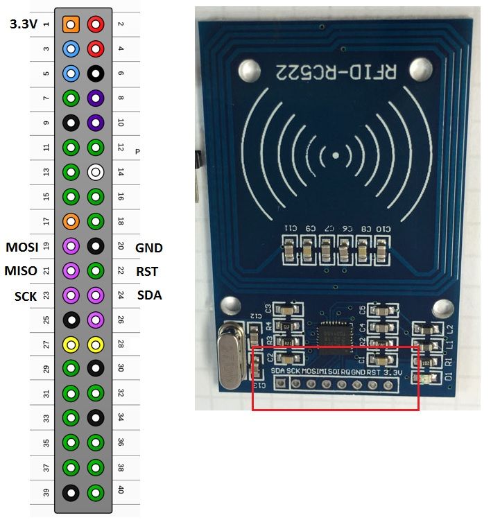
To test the module, I used several diodes and piezo-dynamics. Red and green diodes - to indicate the conditional operation of the conditional lock (red - the lock is closed, green - the lock is open), yellow diode - to indicate the control signal (in real conditions it will be replaced with a lock), piezo-dynamics - beeps when the lock is opened and signals an error. In a real circuit with a lock, it is advisable to use a relay to control the power circuit of the lock.
Diode and speaker wiring diagram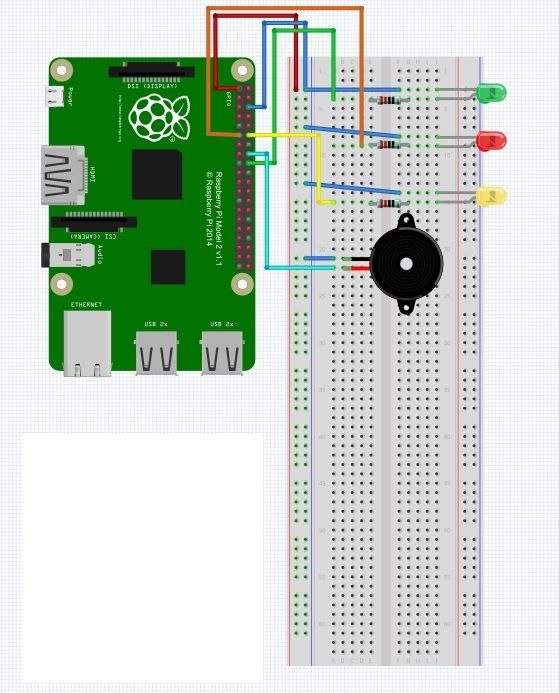
')
Software
First you need to enable SPI on Raspberry, if not enabled. How to do this is written here .
Now you can download the library for working with our module and check the reading and writing of maps. Reading is important for us, in particular reading the UID of the card, for this we enter in the console:
git clone https://github.com/mxgxw/MFRC522-python For correct operation of the downloaded code, you must also download and install SPI-py:
git clone https://github.com/lthiery/SPI-Py sudo python /SPI-Py/setup.py install Now you can read the UID of the card and the information recorded in it. To do this, run their uploaded files as an example:
cd MFRC522-python sudo python Read.py The following should appear on the screen:
Welcome to the MFRC522 data read example Press Ctrl-C to stop. After that, you can bring a card or tag to the reader and we will see its UID
Card detected Card read UID: 60,56,197,101 Size: 8 Sector 8 [12, 0, 0, 0, 0, 0, 0, 0, 0, 0, 0, 0, 0, 0, 0, 0] In this case, we are interested in this part: UID: 60,56,197,101 .
And we can change this part
Spoiler header
, replacing zeros with the values we need: Sector 8 [12, 0, 0, 0, 0, 0, 0, 0, 0, 0, 0, 0, 0, 0, 0, 0] , but this is not what interests us now.
Further, for the operation of our module and other components, I wrote a simple python script based on various sources.
Script with my comments
#!/usr/bin/env python import RPi.GPIO as GPIO import MFRC522 import signal import time red = 11 green = 18 speaker = 16 doorlock = 12 # UID (UID sudo python /MFRC522-python/Read.py card_01 = '6056197101' #white card_02 = '148167101184' #fob card_03 = '13652116101' # # GPIO.setmode(GPIO.BOARD) # , (3v3 - ) GPIO.setup(red, GPIO.OUT, initial=1) # 18 GPIO.setup(green, GPIO.OUT, initial=0) # 11 GPIO.setup(speaker, GPIO.OUT, initial=0) # 16 GPIO.setup(doorlock, GPIO.OUT, initial=0) # 12 continue_reading = True def end_read(signal,frame): # , global continue_reading print "Ctrl+C captured, ending read." continue_reading = False GPIO.cleanup() # Create an object of the class MFRC522 (??) MIFAREReader = MFRC522.MFRC522() while continue_reading: # - UID (status,TagType) = MIFAREReader.MFRC522_Request(MIFAREReader.PICC_REQIDL) # , " " if status == MIFAREReader.MI_OK: print "Card detected" # UID (status,uid) = MIFAREReader.MFRC522_Anticoll() # UID, if status == MIFAREReader.MI_OK: # UID UIDcode = str(uid[0])+str(uid[1])+str(uid[2])+str(uid[3]) print UIDcode # if UIDcode == card_01 or UIDcode == card_03 or UIDcode == card_02: # # , # ( , ), # .. # .. doorlock # , , GPIO.output((red, green, speaker, doorlock), (0,1,1,1)) print "Door open" # 1 time.sleep(1) GPIO.output((red, green, speaker, doorlock), (1,0,0,0)) # , print "Door closed" # , else: GPIO.output((red, green, speaker, doorlock), (1,0,0,0)) time.sleep(0.05) GPIO.output((red, green, speaker, doorlock), (1,0,1,0)) time.sleep(0.05) GPIO.output((red, green, speaker, doorlock), (1,0,0,0)) time.sleep(0.05) GPIO.output((red, green, speaker, doorlock), (1,0,1,0)) time.sleep(0.05) GPIO.output((red, green, speaker, doorlock), (0,1,0,0)) time.sleep(0.05) GPIO.output((red, green, speaker, doorlock), (0,1,1,0)) time.sleep(0.05) GPIO.output((red, green, speaker, doorlock), (0,1,0,0)) time.sleep(0.05) GPIO.output((red, green, speaker, doorlock), (0,1,1,0)) time.sleep(0.05) GPIO.output((red, green, speaker, doorlock), (1,0,0,0)) time.sleep(0.05) GPIO.output((red, green, speaker, doorlock), (1,0,1,0)) time.sleep(0.05) GPIO.output((red, green, speaker, doorlock), (1,0,0,0)) time.sleep(0.05) GPIO.output((red, green, speaker, doorlock), (1,0,1,0)) time.sleep(0.05) GPIO.output((red, green, speaker, doorlock), (0,1,0,0)) time.sleep(0.05) GPIO.output((red, green, speaker, doorlock), (0,1,1,0)) time.sleep(0.05) GPIO.output((red, green, speaker, doorlock), (0,1,0,0)) time.sleep(0.05) GPIO.output((red, green, speaker, doorlock), (0,1,1,0)) time.sleep(0.05) GPIO.output((red, green, speaker, doorlock), (1,0,0,0)) print "Unrecognised Card" Create a file and copy the code into it:
nano rf.py save the file (CTRL + x, y).
Run the script with the command
sudo python rf.py After the following will occur:
the red diode will light up, indicating that our “lock” is closed.
If the card with the number (without commas) is listed, the red diode will go out, the green diode will light up, indicating that the “lock” is open, the yellow diode will light up - in this case it is “control”, indicating that “ lock "is a control signal, piezo dynamics. After a specified time (in our case, 1 second), the diodes and the speaker will return to the initial state, the reader will wait for the card to be read.
If a card from a list is not brought to the reader, the red and green diodes will flash, the piezo-dynamics will squeak intermittently, signaling an error, the yellow diode will not light up (i.e. there is no signal to open the lock). A little less than a second, everything will return to its original state.
A short video illustrating the work:
Source: https://habr.com/ru/post/357956/
All Articles