Smart Redmond SkyPlug RSP-100S Socket Analysis of the design and the electrical circuit diagram. Identifying deficiencies
In this article I want to share with all the important information about the analysis and circuitry of such a device, like the smart REDMOND Smart plug SkyPlug RSP-100S socket, which can wirelessly connect via Bluetooth to a special application installed on Android smartphones. and iOS and allows you to remotely control the inclusion of electrical devices in the electric lighting network ~ 220 V (or 230 V).
I will not describe in more detail about the functions, characteristics and methods of controlling this outlet, since There have already been a lot of reviews and articles on this topic, here are some of them that I would recommend to start by reading who became interested in:
- www.ixbt.com/home/ready-4-sky-gadgets.shtml#1 - Gadgets for Redmond Sky Home: socket, base and tracker;
- geektimes.ru/company/redmond/blog/271932 - "Make any device smart": an overview of the smart Redmond SkyPlug RSP-100S socket.
Once I bought two such outlets in one of the company stores at the sale in order to use them for their intended purpose: to control the lighting of the aquarium and to control the power of the WiFi router connected to the 4G-USB-modem. It happens that the Internet from cellular operators will pee up so that disconnecting and reconnecting does not help, but only a complete power failure of the USB modem helps, or, alternatively, the power of the WiFi router as a whole. Since such a problem often arises and my router with a USB modem is installed on the second floor (there is more reliable reception), and I use the Internet on the first floor, then run to the second floor and briefly de-energize the WiFi router, because the person is a lazy animal. Therefore, there was an idea to manage the “internet reset” remotely via Bluetooth using such an outlet.
')
According to the characteristics indicated on the package and in the instruction manual, any household (in principle and not only household) electrical appliance with a power of no more than 2.3 kW can be connected as a load. But, of course, in order to make sure that this outlet will withstand such power, it is necessary to analyze the design, circuitry and the components used in the outlet and to identify the device’s shortcomings, which I want to draw attention to in this article. And so that everything was clearer, it would be nice to look at the scheme of this outlet. I tried to find the scheme on the Internet, but after a long dig, I did not find this information anywhere and as a result I had to copy it myself.
But why would I need a circuit of this outlet, if I adapted them for such simple needs? I will tell about this in my next article, let it become a small intrigue. :)
1 CONSTRUCTION OF SMART SOCKETS
The first thing that attracts in this outlet is a compact design, it is not bulky, the case is without flaws, everything is smooth and aesthetic.
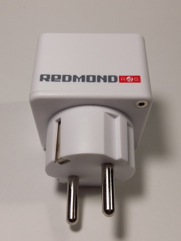
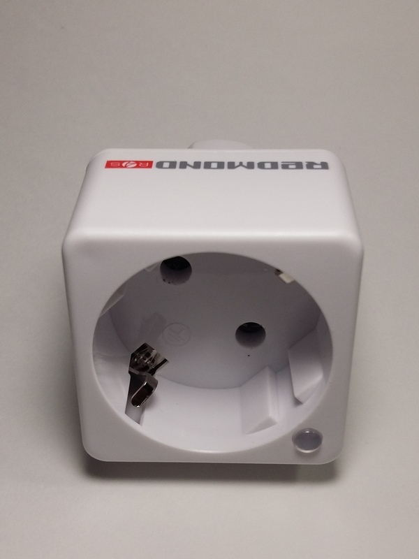
Figure 1 - The appearance of a smart outlet
But, as they say, appearance is deceptive, and you always want to look inside and see how it is, whether everything is as beautiful as the outside.
So, we unscrew those screws with slots under the “asterisk”, the benefit is that I found a attachment for a screwdriver for such screws in my toolbox. Open and look:
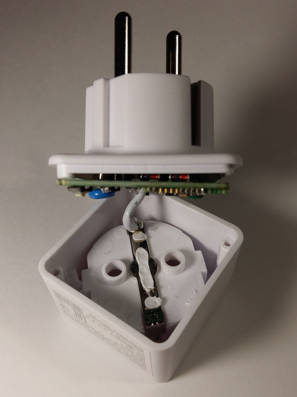
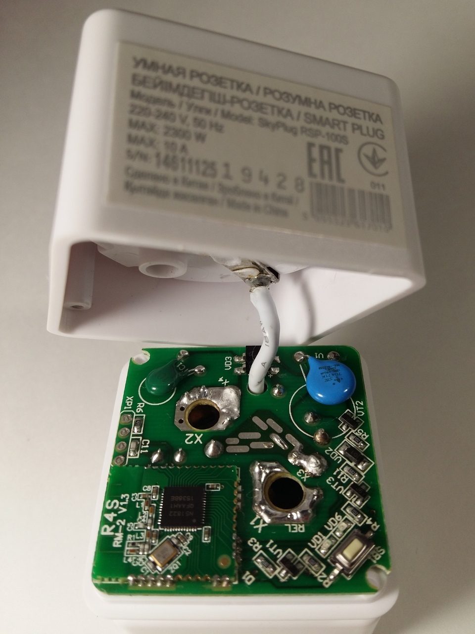
Figure 2 - The internal contents of a smart outlet
The pictures show a printed circuit board with electronic circuit. The printed circuit board is made to the size of the outlet, quite compact, but not without flaws. The first drawback that is striking is that the board after installation and assembly was not washed off the flux, in some places there was a straight layer of flux that the Chinese (yes, it was the Chinese, this outlet was made in China) did not wash . I don’t see the flux in the pictures, because, I confess, I laundered it before the shooting so that all the details of the board could be seen better. Also, another shortcoming is immediately revealed: the boards are not coated with varnish or other special coatings that protect the conductors, components and places of the component ration on the board from moisture, salts, fats and other substances, which couples can be in the kitchen, bathroom and other rooms. And if, say, someone wants to use this outlet in the garage, then there may still be more aggressive environments. But, I'm not sure that this outlet can be used outside of residential premises, and it is not known whether it can withstand negative ambient temperatures.
The pictures show that from the base (the lower part of the socket with the pin contacts) to the socket (the upper part of the socket with the socket for the load plug) the conductor of a relatively large cross section stretches - this is the wire from the ground contacts, it is non-detachable and connected by soldering and to remove the socket, it was necessary this wire is unsolder.

Figure 3 - Installation of the load grounding bracket
In the picture of the socket you can see the method of fastening the grounding contact bracket. It seems that the Chinese, wearing a bracket in place, fix it by melting the tabs with a regular soldering iron. Couldn’t it have been possible to make any special device for melting these projections? Of course, this does not affect the work, but nevertheless, there is a chance that this bracket will come off if the electrical equipment does not connect to the outlet properly and as a result it touches the board where phase voltage is present and a short circuit can occur, which will undoubtedly disable the socket and maybe wiring in the room.
This is how the board installed in the socket base looks like
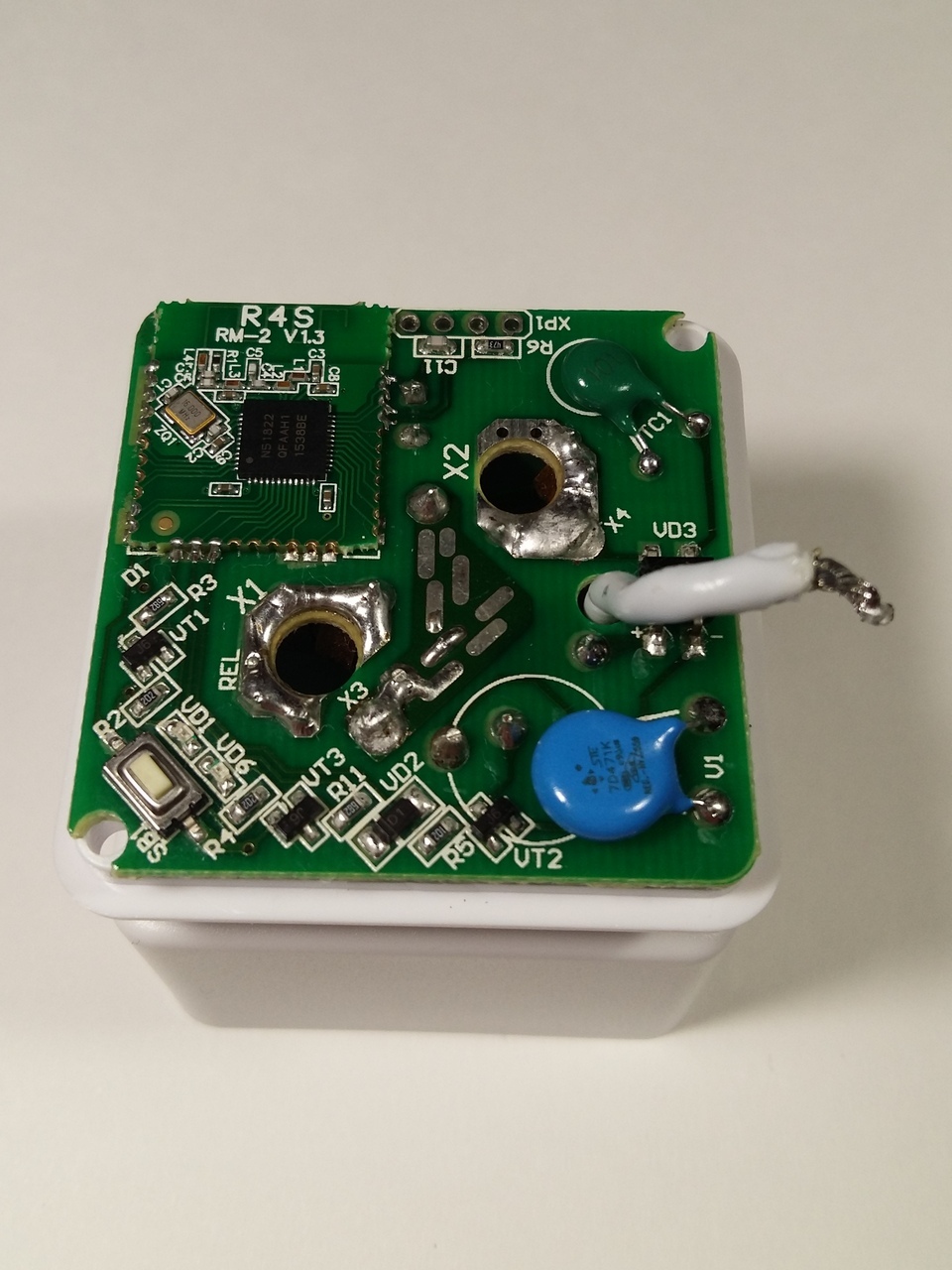
Figure 4 - Installing the board on the base of a smart outlet
I tried to separate the board from the base, but it failed on the first attempt. Then, looking into the gap between the board and the base, it became clear that the board holds. It is directly soldered to the contacts that go from the pins to the circuit board and are soldered in places marked on the board as X3 and X4. We take a soldering iron and tin extractor and release these contacts from the solder, carefully, effortlessly, raising the board to separate it and not to tear out at the same time the metallization of the holes for these contacts. So, the board is separated, and inside looks like as shown in the photo below.
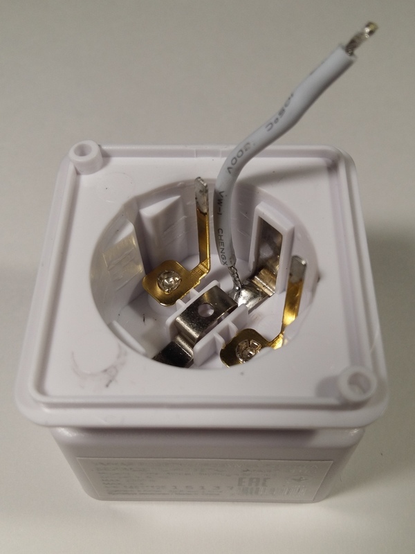
Figure 5 - Fastening the contacts of the plug smart socket
On the basis, it immediately catches the eye that the brass contacts coming from the pins to the board join to the pins themselves by ripping, in my opinion, not a very reliable connection. And one more note: the outlet housing is made of a low-melting polymer, as a result, if under the load of high power the contact of the smart outlet’s pins with the contacts in the wall outlet is not good enough, strong heating is possible in this place and the smart outlet can melt at the junction of the pins which will lead to its damage. It can also be seen that the ground contact bracket in the center has an opening and under the opening you can see the rack (as part of the plastic base construction) for a screw or screw. Again, the Chinese shalturili - saved on the screws. As a result of this saving, I determined that this bracket can be bent if the spring contacts of the ground of wall outlets (or network extension cords) are pressing against it outside the sides. The ends of the external contacts of the bracket should fall into special grooves, from which the contacts may fall out under the influence of the spring contact contacts due to the fact that the bracket is not screwed to the base and therefore does not have sufficient clamping strength.
Go ahead and consider the printed circuit board sockets.
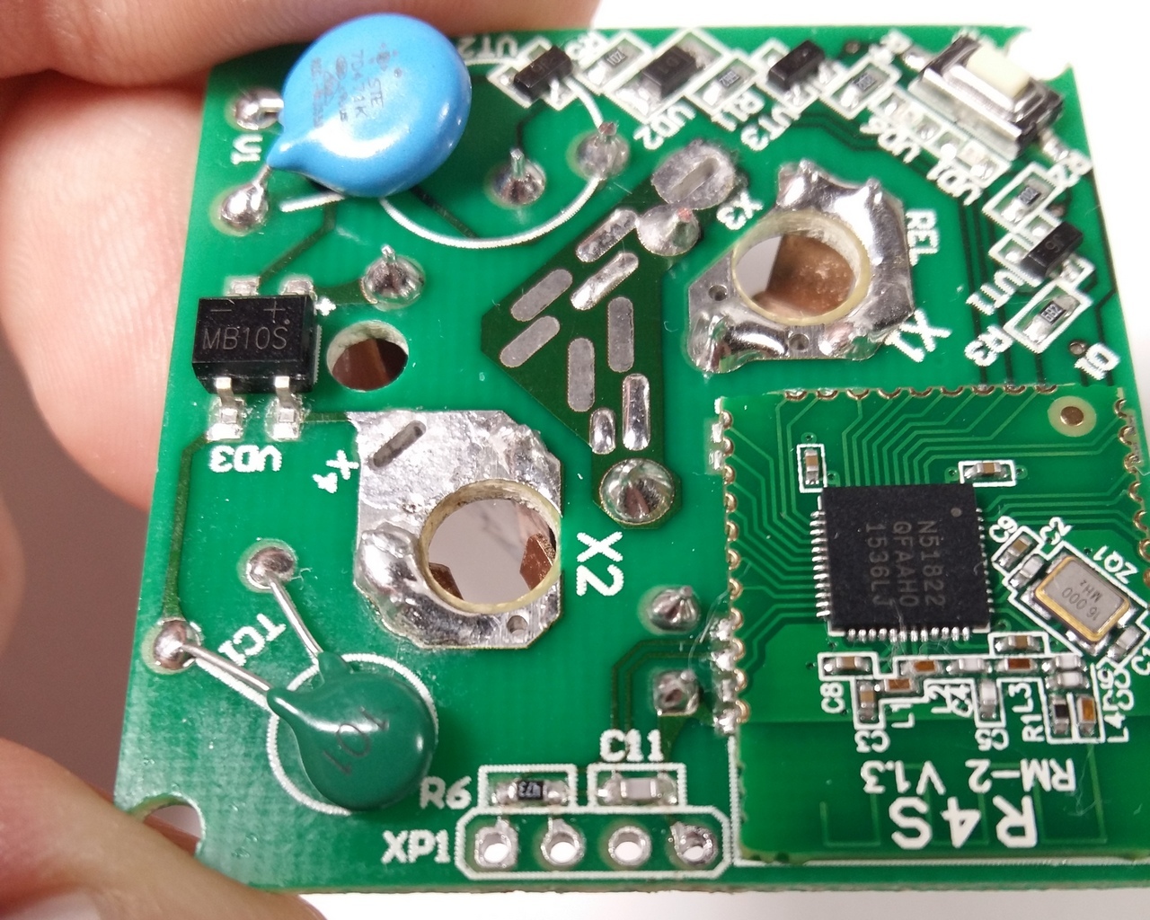
Figure 6 - Printed circuit board - top view
On the top side of the board, another small board immediately catches the eye. Immediately it becomes clear that this is a Bluetooth module, made on a separate scarf, and on this scarf you can see an installed chip with the marking N51822 and an antenna in the form of a zigzag printed conductor. We are looking for datasheet on this chip. My favorite site for searching datasheets for imported components alldatasheet.com did not give any results, immediately the thought arises that probably the chip is not from a particularly well-known manufacturer who did not make it to the lists of this famous site. Then we are looking for datasheets through search engines, as a result, it was found and the microcircuit turned out to be from Nordic Semiconductor, which I hadn’t heard about before, it may have come across its products, but did not attach any importance. The full name of this chip is: nRF51822, according to the data sheet, is a 2.4 GHz multi-protocol Bluetooth controller with low power consumption.
The board also shows a single button that allows you to control the on / off load manually, next to the SMD LEDs button, one of which is green - indicates operation, and the second is red - indicates the authorization mode via Bluetooth with a smartphone.
In addition, there is a varistor for overvoltage protection in the network and some kind of disk element of green color, which, as it turned out, is a thermistor, judging by the designation on the board - TC1. You can still see the diode bridge, marked with the poles of the conclusions.
Also from the top side of the board you can see two rather large holes, labeled X1 and X2 - the load plug goes through them and the load plug is connected to the socket contacts soldered to the board on the other side of the board.
There is a XP1 footprint on the board, in which nothing is installed, most likely, a connector under the programmer cable can be soldered here for in-circuit programming of the Bluetooth controller, since XP1 pads are connected to the handkerchief of the Bluetooth module.
On the remaining elements installed on the upper side of the board, it will be possible to find out by looking at the schematic diagram below.
We turn over the board and see that the Y32F-SS-112HM type electromagnetic relay is installed on the bottom side of the company Yuanze Electric, also unknown to me earlier. Having rummaged on the Internet, I did not find a specific datasheet for this relay, but I found similar ones by design and by name, and found out that the coil of this relay is designed for 12 V, which means that the device should be powered by approximately this voltage. Well, there are doubts that such a small relay will allow switching such powerful loads (10 A / 230 V), I think that it will not be enough for a long time, the contacts will either warm up and the plastic elements of the relay will melt, or the contacts will burn.
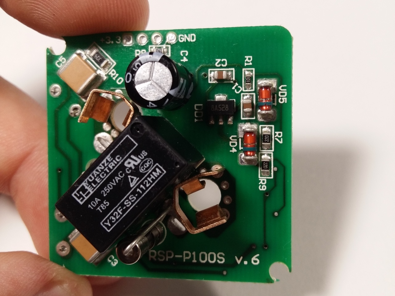
Figure 7 - Printed circuit board - bottom view
On either side of the relay, copper (or copper, but steel) contacts for connecting the load are visible. As I found out initially, as soon as I started using this outlet, these contacts are not sufficiently spring-loaded, i.e. they are not enough to return to their original state after using loads that have a Euro plug whose pins have a diameter of 5 mm, the contacts in the socket expand over time and as a result there will be no possibility to use electrical appliances with a plug whose contacts have a diameter of 4 mm, for example chargers for smartphones. I, for a more reliable connection on my outlet, pressed these contacts a little, for a while it would be enough.
Also, it is impossible not to notice two rather large SMD capacitors, designated as C3 and C5. Obviously, a transformer-free power supply for all elements of the outlet circuit is built on these capacitors.
Here you can see other elements of the scheme, about the functions and applications in this outlet will become clear after analyzing and constructing the concept of the outlet.
2 SCHEME ELECTRIC PRINCIPAL CLEAR SOCKETS
After a detailed analysis of the printed circuit board, all current-carrying printed conductors and elements installed on the board, I drew a schematic diagram of this smart outlet.
Below is a schematic diagram of a smart outlet with the exception of the handkerchiefs of the Bluetooth module, since there, most likely, the nRF51822 IC activation scheme will be typical and can be viewed in the datasheet on this IC.
It should be noted that I did not remove the firmware of the nRF51822 controller of the smart socket, because I do not have the technical means for this, and as long as I don’t care about the firmware, I’m not going to copy such sockets, so if anyone needs it, try it yourself, but then write down the results, if that.
The scheme of a smart socket is not so complicated as it seemed at the very beginning and consists of:
- varistor, which protects both the socket and the load from the power surges;
- fuse;
- transformerless power source based on high-voltage ceramic capacitors, quenching resistor, compact rectifier diode bridge, two 1.3-volt Zener diodes at 12 V, 3.3 V linear stabilizer to power the Bluetooth module;
- a Bluetooth module board, which includes a controller with a Bluetooth radio interface based on the IC nRF51822, into which you can flash the firmware to perform any actions either manually or remotely via the Bluetooth interface;
- Another important component is the electromagnetic relay, which is controlled by the Bluetooth module via a transistor switch, the relay supplies or removes the voltage of the electrical network going to the load;
- manual load control buttons;
- schemes of indication of modes based on LEDs, which are controlled by the same Bluetooth-module through transistor switches.
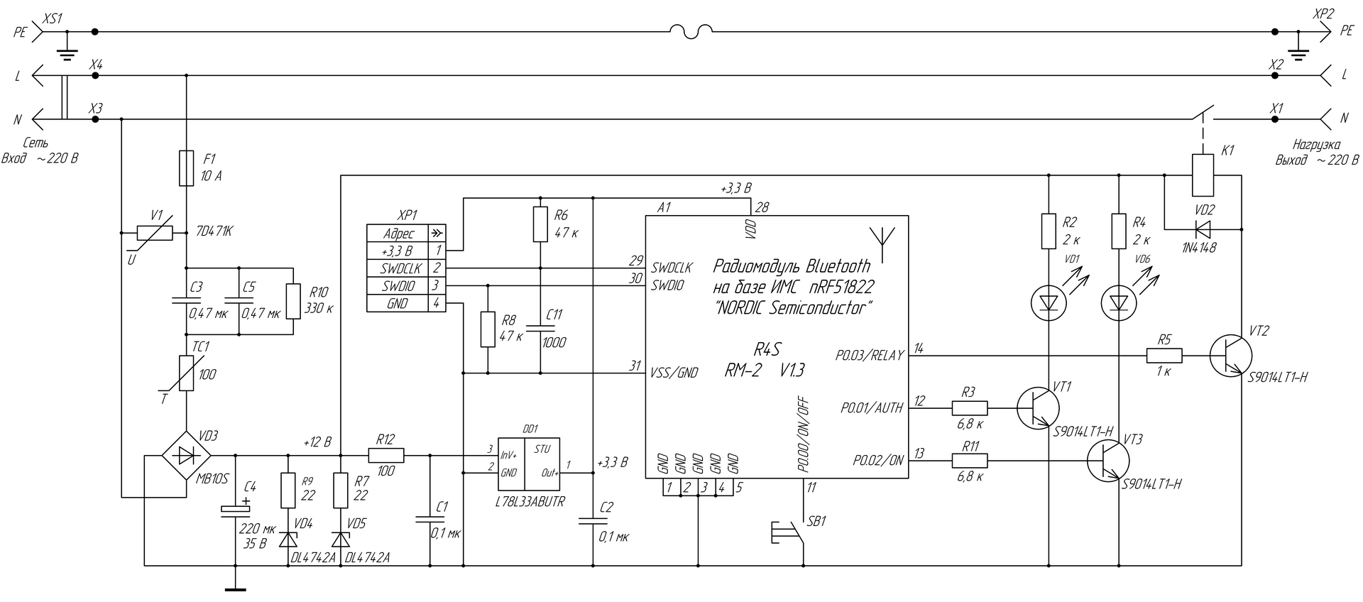
Figure 8 - Electrical schematic diagram of a smart outlet
In conclusion, I want to say that I drew the scheme as it is, up to positional notation and the nominal values of the applied elements. At first glance, the positional notation on the scheme will be numbered randomly, but it just so happened - I drew the scheme as I think it would be more convenient to read it, and I don’t know how it was painted by the developer, maybe he it was backwards, from that and the numbering he has this. I did not begin to renumber the components, since then there would be disagreements with the designations on the PCB. And, by the way, I also portrayed all the developer’s mistakes in the scheme as it is. More precisely, the error I found one, if there are those who also see it - write in a personal, it is not necessary to immediately identify it. The first one who sent the correct answer is a prize, let it be 50 rubles. at the expense of a mobile phone, for example. Then we will discuss this error in the comments, if you want.
PS I forgot to write right away that the pin numbers of the Bluetooth module’s handles are numbered conditionally, these are not the pin numbers of the IC controller itself, these are pin numbers for soldering the card itself, I counted them counterclockwise, starting from a group of pins that 5 pieces connected to common wire circuit (GND).
Now you can read the second part of the article “Smart socket REDMOND Smart plug SkyPlug RSP-100S (Part 2). The main drawback of the outlet and its elimination " , in which I describe the main drawback of this device.
I will not describe in more detail about the functions, characteristics and methods of controlling this outlet, since There have already been a lot of reviews and articles on this topic, here are some of them that I would recommend to start by reading who became interested in:
- www.ixbt.com/home/ready-4-sky-gadgets.shtml#1 - Gadgets for Redmond Sky Home: socket, base and tracker;
- geektimes.ru/company/redmond/blog/271932 - "Make any device smart": an overview of the smart Redmond SkyPlug RSP-100S socket.
Once I bought two such outlets in one of the company stores at the sale in order to use them for their intended purpose: to control the lighting of the aquarium and to control the power of the WiFi router connected to the 4G-USB-modem. It happens that the Internet from cellular operators will pee up so that disconnecting and reconnecting does not help, but only a complete power failure of the USB modem helps, or, alternatively, the power of the WiFi router as a whole. Since such a problem often arises and my router with a USB modem is installed on the second floor (there is more reliable reception), and I use the Internet on the first floor, then run to the second floor and briefly de-energize the WiFi router, because the person is a lazy animal. Therefore, there was an idea to manage the “internet reset” remotely via Bluetooth using such an outlet.
')
According to the characteristics indicated on the package and in the instruction manual, any household (in principle and not only household) electrical appliance with a power of no more than 2.3 kW can be connected as a load. But, of course, in order to make sure that this outlet will withstand such power, it is necessary to analyze the design, circuitry and the components used in the outlet and to identify the device’s shortcomings, which I want to draw attention to in this article. And so that everything was clearer, it would be nice to look at the scheme of this outlet. I tried to find the scheme on the Internet, but after a long dig, I did not find this information anywhere and as a result I had to copy it myself.
But why would I need a circuit of this outlet, if I adapted them for such simple needs? I will tell about this in my next article, let it become a small intrigue. :)
1 CONSTRUCTION OF SMART SOCKETS
The first thing that attracts in this outlet is a compact design, it is not bulky, the case is without flaws, everything is smooth and aesthetic.
Figure 1 - The appearance of a smart outlet
But, as they say, appearance is deceptive, and you always want to look inside and see how it is, whether everything is as beautiful as the outside.
So, we unscrew those screws with slots under the “asterisk”, the benefit is that I found a attachment for a screwdriver for such screws in my toolbox. Open and look:
Figure 2 - The internal contents of a smart outlet
The pictures show a printed circuit board with electronic circuit. The printed circuit board is made to the size of the outlet, quite compact, but not without flaws. The first drawback that is striking is that the board after installation and assembly was not washed off the flux, in some places there was a straight layer of flux that the Chinese (yes, it was the Chinese, this outlet was made in China) did not wash . I don’t see the flux in the pictures, because, I confess, I laundered it before the shooting so that all the details of the board could be seen better. Also, another shortcoming is immediately revealed: the boards are not coated with varnish or other special coatings that protect the conductors, components and places of the component ration on the board from moisture, salts, fats and other substances, which couples can be in the kitchen, bathroom and other rooms. And if, say, someone wants to use this outlet in the garage, then there may still be more aggressive environments. But, I'm not sure that this outlet can be used outside of residential premises, and it is not known whether it can withstand negative ambient temperatures.
The pictures show that from the base (the lower part of the socket with the pin contacts) to the socket (the upper part of the socket with the socket for the load plug) the conductor of a relatively large cross section stretches - this is the wire from the ground contacts, it is non-detachable and connected by soldering and to remove the socket, it was necessary this wire is unsolder.
Figure 3 - Installation of the load grounding bracket
In the picture of the socket you can see the method of fastening the grounding contact bracket. It seems that the Chinese, wearing a bracket in place, fix it by melting the tabs with a regular soldering iron. Couldn’t it have been possible to make any special device for melting these projections? Of course, this does not affect the work, but nevertheless, there is a chance that this bracket will come off if the electrical equipment does not connect to the outlet properly and as a result it touches the board where phase voltage is present and a short circuit can occur, which will undoubtedly disable the socket and maybe wiring in the room.
This is how the board installed in the socket base looks like
Figure 4 - Installing the board on the base of a smart outlet
I tried to separate the board from the base, but it failed on the first attempt. Then, looking into the gap between the board and the base, it became clear that the board holds. It is directly soldered to the contacts that go from the pins to the circuit board and are soldered in places marked on the board as X3 and X4. We take a soldering iron and tin extractor and release these contacts from the solder, carefully, effortlessly, raising the board to separate it and not to tear out at the same time the metallization of the holes for these contacts. So, the board is separated, and inside looks like as shown in the photo below.
Figure 5 - Fastening the contacts of the plug smart socket
On the basis, it immediately catches the eye that the brass contacts coming from the pins to the board join to the pins themselves by ripping, in my opinion, not a very reliable connection. And one more note: the outlet housing is made of a low-melting polymer, as a result, if under the load of high power the contact of the smart outlet’s pins with the contacts in the wall outlet is not good enough, strong heating is possible in this place and the smart outlet can melt at the junction of the pins which will lead to its damage. It can also be seen that the ground contact bracket in the center has an opening and under the opening you can see the rack (as part of the plastic base construction) for a screw or screw. Again, the Chinese shalturili - saved on the screws. As a result of this saving, I determined that this bracket can be bent if the spring contacts of the ground of wall outlets (or network extension cords) are pressing against it outside the sides. The ends of the external contacts of the bracket should fall into special grooves, from which the contacts may fall out under the influence of the spring contact contacts due to the fact that the bracket is not screwed to the base and therefore does not have sufficient clamping strength.
Go ahead and consider the printed circuit board sockets.
Figure 6 - Printed circuit board - top view
On the top side of the board, another small board immediately catches the eye. Immediately it becomes clear that this is a Bluetooth module, made on a separate scarf, and on this scarf you can see an installed chip with the marking N51822 and an antenna in the form of a zigzag printed conductor. We are looking for datasheet on this chip. My favorite site for searching datasheets for imported components alldatasheet.com did not give any results, immediately the thought arises that probably the chip is not from a particularly well-known manufacturer who did not make it to the lists of this famous site. Then we are looking for datasheets through search engines, as a result, it was found and the microcircuit turned out to be from Nordic Semiconductor, which I hadn’t heard about before, it may have come across its products, but did not attach any importance. The full name of this chip is: nRF51822, according to the data sheet, is a 2.4 GHz multi-protocol Bluetooth controller with low power consumption.
The board also shows a single button that allows you to control the on / off load manually, next to the SMD LEDs button, one of which is green - indicates operation, and the second is red - indicates the authorization mode via Bluetooth with a smartphone.
In addition, there is a varistor for overvoltage protection in the network and some kind of disk element of green color, which, as it turned out, is a thermistor, judging by the designation on the board - TC1. You can still see the diode bridge, marked with the poles of the conclusions.
Also from the top side of the board you can see two rather large holes, labeled X1 and X2 - the load plug goes through them and the load plug is connected to the socket contacts soldered to the board on the other side of the board.
There is a XP1 footprint on the board, in which nothing is installed, most likely, a connector under the programmer cable can be soldered here for in-circuit programming of the Bluetooth controller, since XP1 pads are connected to the handkerchief of the Bluetooth module.
On the remaining elements installed on the upper side of the board, it will be possible to find out by looking at the schematic diagram below.
We turn over the board and see that the Y32F-SS-112HM type electromagnetic relay is installed on the bottom side of the company Yuanze Electric, also unknown to me earlier. Having rummaged on the Internet, I did not find a specific datasheet for this relay, but I found similar ones by design and by name, and found out that the coil of this relay is designed for 12 V, which means that the device should be powered by approximately this voltage. Well, there are doubts that such a small relay will allow switching such powerful loads (10 A / 230 V), I think that it will not be enough for a long time, the contacts will either warm up and the plastic elements of the relay will melt, or the contacts will burn.
Figure 7 - Printed circuit board - bottom view
On either side of the relay, copper (or copper, but steel) contacts for connecting the load are visible. As I found out initially, as soon as I started using this outlet, these contacts are not sufficiently spring-loaded, i.e. they are not enough to return to their original state after using loads that have a Euro plug whose pins have a diameter of 5 mm, the contacts in the socket expand over time and as a result there will be no possibility to use electrical appliances with a plug whose contacts have a diameter of 4 mm, for example chargers for smartphones. I, for a more reliable connection on my outlet, pressed these contacts a little, for a while it would be enough.
Also, it is impossible not to notice two rather large SMD capacitors, designated as C3 and C5. Obviously, a transformer-free power supply for all elements of the outlet circuit is built on these capacitors.
Here you can see other elements of the scheme, about the functions and applications in this outlet will become clear after analyzing and constructing the concept of the outlet.
2 SCHEME ELECTRIC PRINCIPAL CLEAR SOCKETS
After a detailed analysis of the printed circuit board, all current-carrying printed conductors and elements installed on the board, I drew a schematic diagram of this smart outlet.
Below is a schematic diagram of a smart outlet with the exception of the handkerchiefs of the Bluetooth module, since there, most likely, the nRF51822 IC activation scheme will be typical and can be viewed in the datasheet on this IC.
It should be noted that I did not remove the firmware of the nRF51822 controller of the smart socket, because I do not have the technical means for this, and as long as I don’t care about the firmware, I’m not going to copy such sockets, so if anyone needs it, try it yourself, but then write down the results, if that.
The scheme of a smart socket is not so complicated as it seemed at the very beginning and consists of:
- varistor, which protects both the socket and the load from the power surges;
- fuse;
- transformerless power source based on high-voltage ceramic capacitors, quenching resistor, compact rectifier diode bridge, two 1.3-volt Zener diodes at 12 V, 3.3 V linear stabilizer to power the Bluetooth module;
- a Bluetooth module board, which includes a controller with a Bluetooth radio interface based on the IC nRF51822, into which you can flash the firmware to perform any actions either manually or remotely via the Bluetooth interface;
- Another important component is the electromagnetic relay, which is controlled by the Bluetooth module via a transistor switch, the relay supplies or removes the voltage of the electrical network going to the load;
- manual load control buttons;
- schemes of indication of modes based on LEDs, which are controlled by the same Bluetooth-module through transistor switches.
Figure 8 - Electrical schematic diagram of a smart outlet
In conclusion, I want to say that I drew the scheme as it is, up to positional notation and the nominal values of the applied elements. At first glance, the positional notation on the scheme will be numbered randomly, but it just so happened - I drew the scheme as I think it would be more convenient to read it, and I don’t know how it was painted by the developer, maybe he it was backwards, from that and the numbering he has this. I did not begin to renumber the components, since then there would be disagreements with the designations on the PCB. And, by the way, I also portrayed all the developer’s mistakes in the scheme as it is. More precisely, the error I found one, if there are those who also see it - write in a personal, it is not necessary to immediately identify it. The first one who sent the correct answer is a prize, let it be 50 rubles. at the expense of a mobile phone, for example. Then we will discuss this error in the comments, if you want.
PS I forgot to write right away that the pin numbers of the Bluetooth module’s handles are numbered conditionally, these are not the pin numbers of the IC controller itself, these are pin numbers for soldering the card itself, I counted them counterclockwise, starting from a group of pins that 5 pieces connected to common wire circuit (GND).
Now you can read the second part of the article “Smart socket REDMOND Smart plug SkyPlug RSP-100S (Part 2). The main drawback of the outlet and its elimination " , in which I describe the main drawback of this device.
Source: https://habr.com/ru/post/357936/
All Articles