Making the PC turn on cotton per evening
Foreword
In childhood, watching many American films, was delighted with the way the actors turned off the light in the room "clapping their hands", I always wanted the same thing at home. In recent years, the PC has become an integral part of my life: coming home and having lost your shoes, the first step is to turn on your “iron horse” and wait for it to load. Of course, in recent years, with the advent of SSD, this expectation has been minimized, but nevertheless, along with the approach to the computer, some time is lost. Yes, and actually why bother to go into the room at all, beat the button with your feet, if you can do some kind of remote way to turn on "my charms."
Actually, over time, two “dreams” merged: to turn on the PC for cotton. At the moment I am studying at the university and the time has come to do coursework on circuitry, and the teacher said that you can make it in hardware and not on paper, which is more interesting in my opinion. Thus, the chance to “kill two birds with one stone” turned up - to implement the old idea and pass the course project. The initial idea was to make some device that can be placed on the case, power it from the power supply, connect it to the button via a relay and clap the loop. As a result, they decided to move away a little from this idea by expanding it a bit: the system will now consist of two blocks connected via Bluetooth. One block will pick up the clap and send a special signal to the second block, the second block will receive this signal and close the relay.
Where to begin
First of all, it was necessary to decide on which hardware to implement my project. The choice fell on the Arduino platform. Why precisely Arduino? In this article, I will not list the technical characteristics of this platform at least because it is not about this. Actually the answer to this question lies in three reasons:
- Cheapness - in China, microcontrollers with this platform can be found for $ 5 or even less
- Ease of use - on the Internet a lot of guides on this platform and to understand them is easy
- A huge number of all kinds of sensors
The latter way is important for those who want to do something else with their microcontroller. After all, the next day you can screw something else on the board, reflash it and it will perform completely different tasks. In general, back to our topic.
Actually make a list of what we need for this:
')
- 2x Arduino Uno R3 - one for each unit
- 2x Bluetooth HC-05 - Again, one for each unit, and the main thing is HC-05, because only they support the Master and Slave modes
- The microphone is a simple electret microphone, it costs only a penny.
- Relay
- 2x LEDs - red and green
- Any wiring, resistors, etc.
- And of course the soldering iron
Getting started
Consider our microcontroller

As you can see, it has analog pins signed with the letter A (for example, A0), inputs for external power, outputs for power supply + 5V and + 3.3V, digital pins, outputs to the ground, etc.
You can connect it to your computer via USB, the benefit comes with a cable. And even if you don’t have one, you can buy it at any electronics store. To work directly with Arduino there is their own very convenient IDE, which can be obtained from the official site .
In order to continue to work with Arduino, you must still tell at least a little about it.
Microcontrollers for Arduino are distinguished by the presence of a bootloader pre-flashed in them. Using this bootloader, the user loads his program into the microcontroller without using traditional individual hardware programmers. The loader connects to the computer via the USB interface (if it is on the card) or using a separate UART-USB adapter. Bootloader support is built into the Arduino IDE and runs in one click.
In case of overwriting the bootloader or buying a microcontroller without a bootloader, the developers provide the opportunity to flash the bootloader into the microcontroller on their own. For this, the Arduino IDE has built-in support for several popular low-cost programmers, and most Arduino boards have a pin-in connector for in-circuit programming (ICSP for AVR, JTAG for ARM).
The Arduino programming language is a standard C ++ (using the AVR-GCC compiler) with some special features.
Programs written by the Arduino programmer are sketches (or sometimes sketches - barbarism from an English sketch) and are saved in files with the ino extension. These files are processed by the Arduino preprocessor before compilation. It is also possible to create and connect standard C ++ files to the project.
So, after downloading the Arduino IDE from the official site and installing it, open it and see it:

Our sketch is divided into 2 blocks - setup () and loop (). The first block is written what should be initially initialized when the controller is turned on in the network. In the second - the actual code itself, which will be executed continuously. Actually all this follows from the names of these blocks.
First block
First of all, it was necessary to assemble and connect a microphone. In fact, the electret microphone that we bought is a kind of two-leg capacitor:
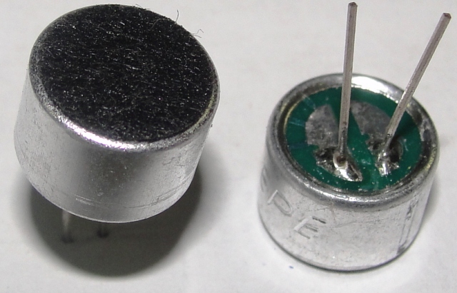
The leg with the characteristic three stripes, as in the image above, is the “minus” of the microphone, respectively, the second leg is the “plus”, the main thing is not to confuse, otherwise the microphone will not work. Actually a good googling, it turned out that in the first place you simply wouldn’t connect a microphone, and secondly the signal would be very weak, that is, you would most likely need an operational amplifier. On the seller’s website, where the microphone was bought, there was such a scheme:
Without amplifiers, just an RC circuit, I thought I wasn’t, I’ll collect and see if it works or not. The blessing of the house lay the necessary resistors and a capacitor. Also for the reliability of the connection, so that it does not dangle on the wires in the air, take the PCB, which is also sold in any store of radio components. It turned out something like this:

It may not be very neat, but the main thing to work remains to be checked. Our microphone now has 3 legs: + 5V, GND (ground) and analog output. Connect these legs, respectively, to 5V, GND and A0 input of the controller. Iii after a lot of trial and error, everything turned out! The microphone really works. The Arduino ADC outputs values from 0 to 1024. It remains to connect two LEDs for at least some visual interaction with the system. It is impossible to connect the LED directly to the power supply; otherwise, we will burn it. To avoid this, we hang on the "+" LED resistor 220 OM. Usually a short leg is a minus, and a long leg is a plus. So the “-” LED is connected to the GND output on the board, and the “+” to the digital output. Since we have 2 LEDs, we’ll make a common ground for them, connect red to 13 pin and green to 12th. When registering at least some sound will turn on a red LED. If we register the sound first, then silence for some time, and then the sound again, then we light the green LED. In fact, everything is simple. And in practice it turned out too. The sketch itself turned out like this:
#define MIC A0 // , int ClapMargin = 9; // ( ) int mic_prev = 0; int SilenceLen=1500; // int NextClapLen = 2500; //, . int SkipLen = 800; // void setup() { analogReference(INTERNAL);// 1.1 Serial.begin(9600); pinMode(12, OUTPUT); pinMode(13, OUTPUT); } int ReadNext() { int result; int d; d = analogRead(MIC); // result = abs(mic_prev-d); // mic_prev = d; // return result; // } int WaitForClap(int WaitLen) { int d, i; i = 0; // do { d = ReadNext(); // i++; // if (d > ClapMargin) { // Serial.println(d); return d; // } if ( (WaitLen != -1) && (i >= WaitLen) ) { // WaitLen WaitLen -1 return 0; // 0 } } while (1); } //- SkipLen void Skip(int SkipLen) { int i; for (i=0; i<SkipLen; i++) { ReadNext(); } } void loop() { int d1, d2; if(WaitForClap(-1)> ClapMargin)// { digitalWrite(12, HIGH);// Serial.println("raz"); Skip(SkipLen); d1 = WaitForClap(SilenceLen); // Serial.println(d1); if (d1 == 0) { digitalWrite(12, HIGH); Skip(500); d2 = WaitForClap(NextClapLen); // 2 if (d2 > ClapMargin) { digitalWrite(12, LOW);// digitalWrite(13, HIGH);// delay(1000); } } } digitalWrite(12, LOW);// digitalWrite(13, LOW); Skip(SkipLen); } So, we learned to catch the necessary signal, it remains to inform the second block about the presence of cotton. To do this, we need Bluetooth modules. I took the Bluetooth hc-05 shield, which looks like this:
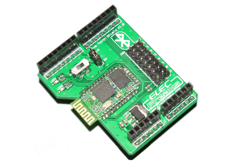
Simply we connect it to our Uno pin to pin, so we connect the module itself and duplicate the outputs of our board. It should look something like this (Shields can be in several different variations, the essence is the same):

Also on the Bluetooth Shield you can see a lever that has two positions: H and L. H-mode Master (Master), L-mode Slave (Slave). In this case, put the lever on the Master. So, having connected the bluetooth module, we can connect our LEDs and a microphone to the same pins from above. In general, with this block finished, go to the next.
Second block
In the second block, we will need an electromagnetic relay, a double external socket, a wire for connecting to a 220 V electrical network, and another Bluetooth Shield HC-05.
Shield is connected to the board in exactly the same way, the only difference will be that the lever must be set to L - SLave mode.
One outlet will be constantly energized to power the unit, the second will be shorted to the relay, so it will be possible, then supply the mains voltage to it, then remove it.
So we connect the relay. The principle of its operation is simple and consists in the following: 2 of the legs of the relay are wound on an inductor, applying voltage to it creates an electromagnetic field, which attracts the so-called anchor inside the relay, thereby closing the circuit. Removing the voltage from the coil, the anchor returns to its original state, breaking the circuit. Thus, the relay is a kind of key.
So, we need a relay, which, when applied to a 5V coil, will close the circuit to us. In this case, you need to choose a relay that can pass the currents necessary to turn on the PC. Given that most modern PCs consume from 450 W to 1000 W, we are more than enough relay passing through a current of 6 Amps. In the nearest electronics store, this Chinese tianbo hjr-3ff-sz was acquired:

As you can see, he has 5 legs, 2 of which are on the coil, it remains only to find out which ones. To do this, google it and find the following scheme:
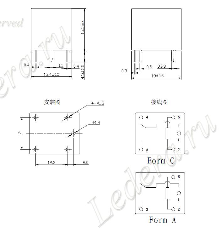
Connect the 2nd leg to the GND board, and the 5th to the 13th digital output. The socket itself is connected to the 1st and 3rd leg of the electromagnetic relay so that the initial state of the socket is turned off. The block is ready, it remains only to load the sketch. Code for this block:
#include <SoftwareSerial.h>// Bluetooth #include <Wire.h> #define rxPin 2 #define txPin 3 SoftwareSerial btSerial(rxPin, txPin); void setup() { // put your setup code here, to run once: // Bluetooth Serial.begin(9600); pinMode(rxPin, INPUT); pinMode(txPin, OUTPUT); btSerial.begin(38400); pinMode(13, OUTPUT);// 13 } void loop() { // put your main code here, to run repeatedly: if(btSerial.available()) { char c=(char)btSerial.read(); Serial.println(c); digitalWrite(13, !digitalRead(13));// , , 13 } } We also upgrade the code for the first block, adding the pairing of bluetooth to each other:
#include <SoftwareSerial.h> #include <Wire.h> #define MIC A0 // , int ClapMargin = 9; // ( ) int mic_prev = 0; int SilenceLen=1500; // int NextClapLen = 2500; //, . int SkipLen = 800; // #define rxPin 2 #define txPin 3 SoftwareSerial btSerial(rxPin, txPin); void setup() { // put your setup code here, to run once: analogReference(INTERNAL);// 1.1 Serial.begin(9600); pinMode(12, OUTPUT);// 12 13 pinMode(13, OUTPUT); // define pin modes for tx, rx pins: // Bluetooth bluetooth pinMode(rxPin, INPUT); pinMode(txPin, OUTPUT); btSerial.begin(38400); Serial.println("Serial started"); digitalWrite(12, HIGH);// btSerial.println("AT"); while (!btSerial.available()); while (btSerial.available() > 0) char c = btSerial.read(); btSerial.println("AT+INIT"); while (!btSerial.available()); while (btSerial.available() > 0) char c = btSerial.read(); btSerial.println("AT+INQ"); while (!btSerial.available()); while (btSerial.available() > 0) char c = btSerial.read(); btSerial.println("AT+LINK=2014,5,191146");//2014,5,191146 - while (!btSerial.available()); while (btSerial.available() > 0) char c = btSerial.read(); digitalWrite(12, LOW);// } int ReadNext() { int result; int d; d = analogRead(MIC); // result = abs(mic_prev-d); // mic_prev = d; // return result; // } int WaitForClap(int WaitLen) { int d, i; i = 0; // do { d = ReadNext(); // i++; // if (d > ClapMargin) { // Serial.println(d); return d; // } if ( (WaitLen != -1) && (i >= WaitLen) ) { // WaitLen WaitLen -1 return 0; // 0 } } while (1); } //- SkipLen void Skip(int SkipLen) { int i; for (i=0; i<SkipLen; i++) { ReadNext(); } } void loop() { int d1, d2; if(WaitForClap(-1)> ClapMargin)// { digitalWrite(12, HIGH); Serial.println("raz"); Skip(SkipLen); d1 = WaitForClap(SilenceLen); // Serial.println(d1); if (d1 == 0) { digitalWrite(12, HIGH); Skip(500); d2 = WaitForClap(NextClapLen); // 2 if (d2 > ClapMargin) { digitalWrite(12, LOW);// digitalWrite(13, HIGH);// btSerial.print('1');// Bluetooth delay(1000); } } } digitalWrite(12, LOW);// digitalWrite(13, LOW); Skip(SkipLen); } Result
So the bluetooth is connected, the microphone is working, the LEDs are working, the cotton is identified, the signal to the second unit is transmitted, all that remains is to carefully assemble it into the enclosures and configure the BIOS to turn on when power is applied.
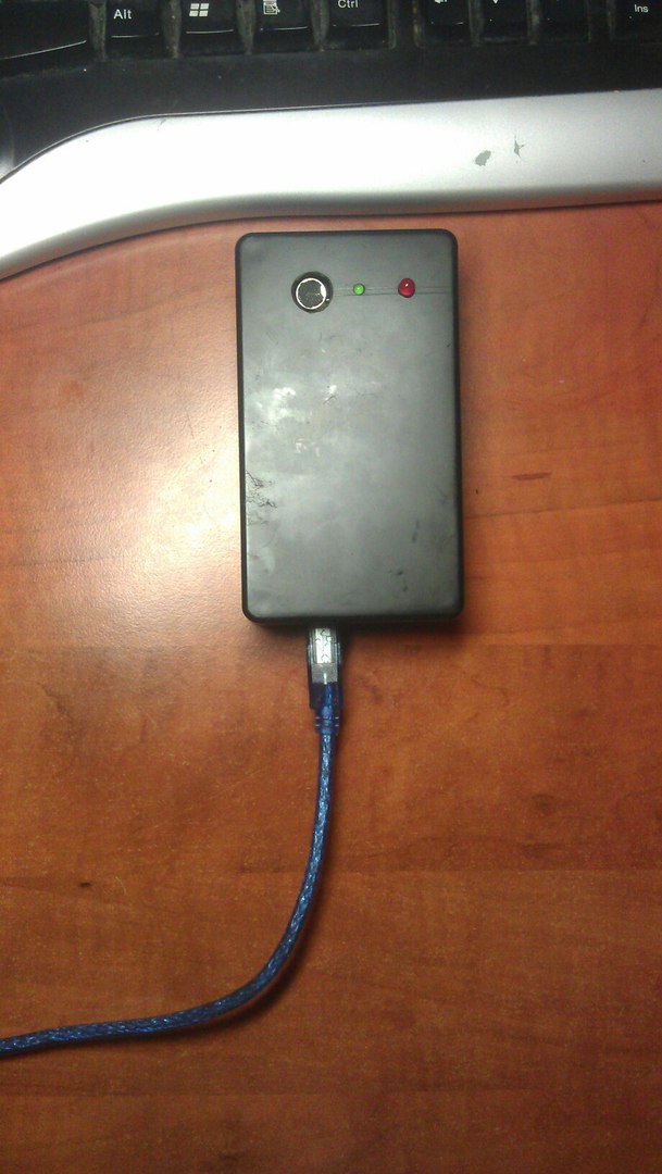
Here's what happened:
1st unit (power output on the side of the case, on the top visible green and red LEDs and a microphone).
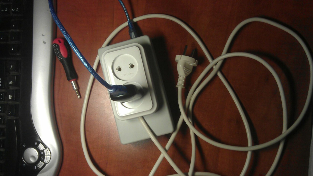
2nd unit (power is also displayed on the side of the case, on top of 2 sockets, one is constantly powered to power the microcontroller through the adapter for the phone, the second is for connecting the PC itself).
We look at the result:
Results
- Arduino is awesome. Cheap microcontrollers, a lot of sensors, a lot of various guides on the Internet, as well as the C ++ language
- Such a thing you can really do yourself in the evening, the main thing is to buy everything in advance
- This device can be used not only to turn on the PC, but also to turn on other electrical devices, such as lamps. And this is a big plus
- This idea can be expanded, for example, by creating many such devices, connecting them into a single network, and managing it via Bluetooth using a smartphone, well, it is so, for the future
Source: https://habr.com/ru/post/357930/
All Articles