Keyboard layout indicator in the form of a color cube on the table using Arduino
As you know, people are divided into two categories: those who switch the layout using Ctrl + Shift and those who use Alt + Shift. And then there are the lucky ones who do not need it - those who have only one layout (usually English). The rest envy them and suffer with two, or even three, layouts: English, Russian, Ukrainian (Belarusian, Kazakh, etc.).
The problem is that when switching a language, you have to constantly look at this little language icon. There are other options:
- Using separate combinations for different languages (Ctrl + 1 (2.3)) - programmers who work in different IDEs will agree that this is not an option, since such combinations are often as busy and overlapping, and using others in the IDE is unusual. The nuance is that the layout in the operating system is in fact the layout for the current program, and not for everything (I wondered if not everyone noticed it). Ie, if Word is now active with the English layout, then, switching to the browser, there may be another layout. And you have to either look at the icon again or re-enter, for example, Ctrl + 1, even if the language has not changed.
- Using programs like Punto switcher that are trying to automatically fix the layout doesn’t always work out correctly and often makes typing even more difficult.
- Use programs that switch themes Windows - not everyone will like the multi-colored taskbar or windows.
Idea
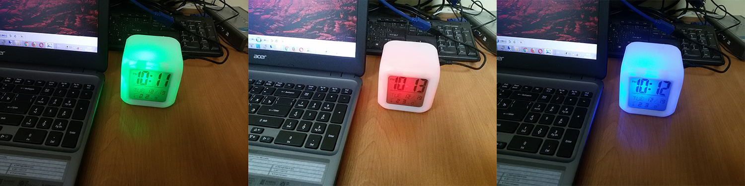
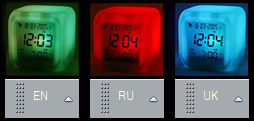
And let's make an Arduino based cube with LED backlight that will stand on the table and change its color depending on the layout. Each language is a different color. For example, English is green, Russian is red, Ukrainian is blue. This will allow you to see the language of the current application with peripheral vision.
Immediately I say, it is not difficult to do even non-electronics.
Hardware
Need to:
- Arduino Micro - plus the board is that there is a micro-USB, which allows you to connect it with a popular cable to a PC. You can use any compact micro USB card.
- RGB LED. You can use instead of it and 3 multi-colored LEDs.
- 3 220 Ohm resistors.
- “Cube”.
Anything can be used as a “cube”. I bought an alarm clock from Aliexpress.com in the form of a cube. Here is the cube itself:
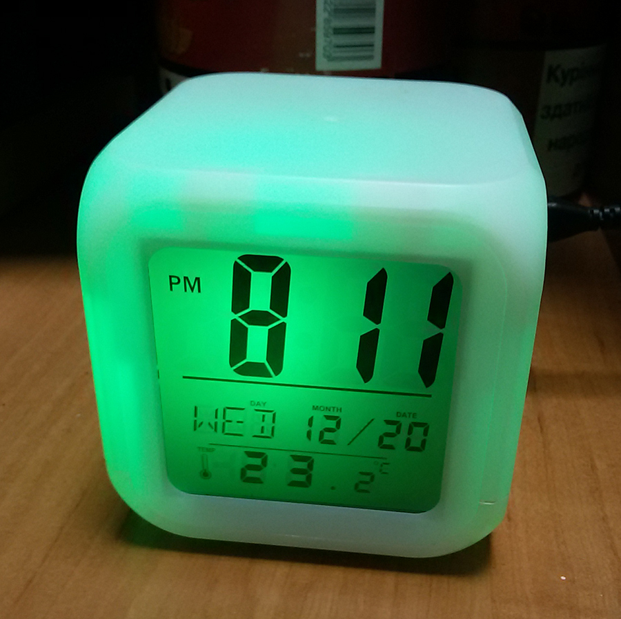
I liked the size, price and additional use in the form of a temperature sensor (the clock in the cube itself is not accurate, therefore useless). On the same Aliexpress.com you can find other options:
- pyramid clock;
- just a cube with backlight.
Considering today's capabilities, it is possible to print something on a 3D printer. And just use the frame with the photo.
Write the code
Everything is simple, we read in the loop COM-port. When reading the value of 1 - turn on the green LED, the rest extinguish. Upon receipt of 2 - turn on the red LED, the rest extinguish. Upon receipt of 3 - turn on the blue LED, the rest extinguish.
int inByte = 0; int LED_R = 5;// int LED_G = 6;// int LED_B = 9;// int RV = 255; // int GV = 255;// int BV = 255;// void setup() { Serial.begin(9600); pinMode(LED_R, OUTPUT); pinMode(LED_G, OUTPUT); pinMode(LED_B, OUTPUT); } void loop() { if (Serial.available() > 0) { delay(100); inByte = Serial.read(); if (inByte == '2') { // RU analogWrite(LED_R, RV); analogWrite(LED_G, 0); analogWrite(LED_B, 0); } else if (inByte == '1') { // EN analogWrite(LED_R, 0); analogWrite(LED_G, GV); analogWrite(LED_B, 0); } else if (inByte == '3') { //UA analogWrite(LED_R, 0); analogWrite(LED_G, 0); analogWrite(LED_B, BV); } } } Solder
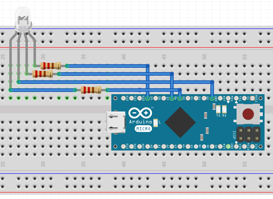
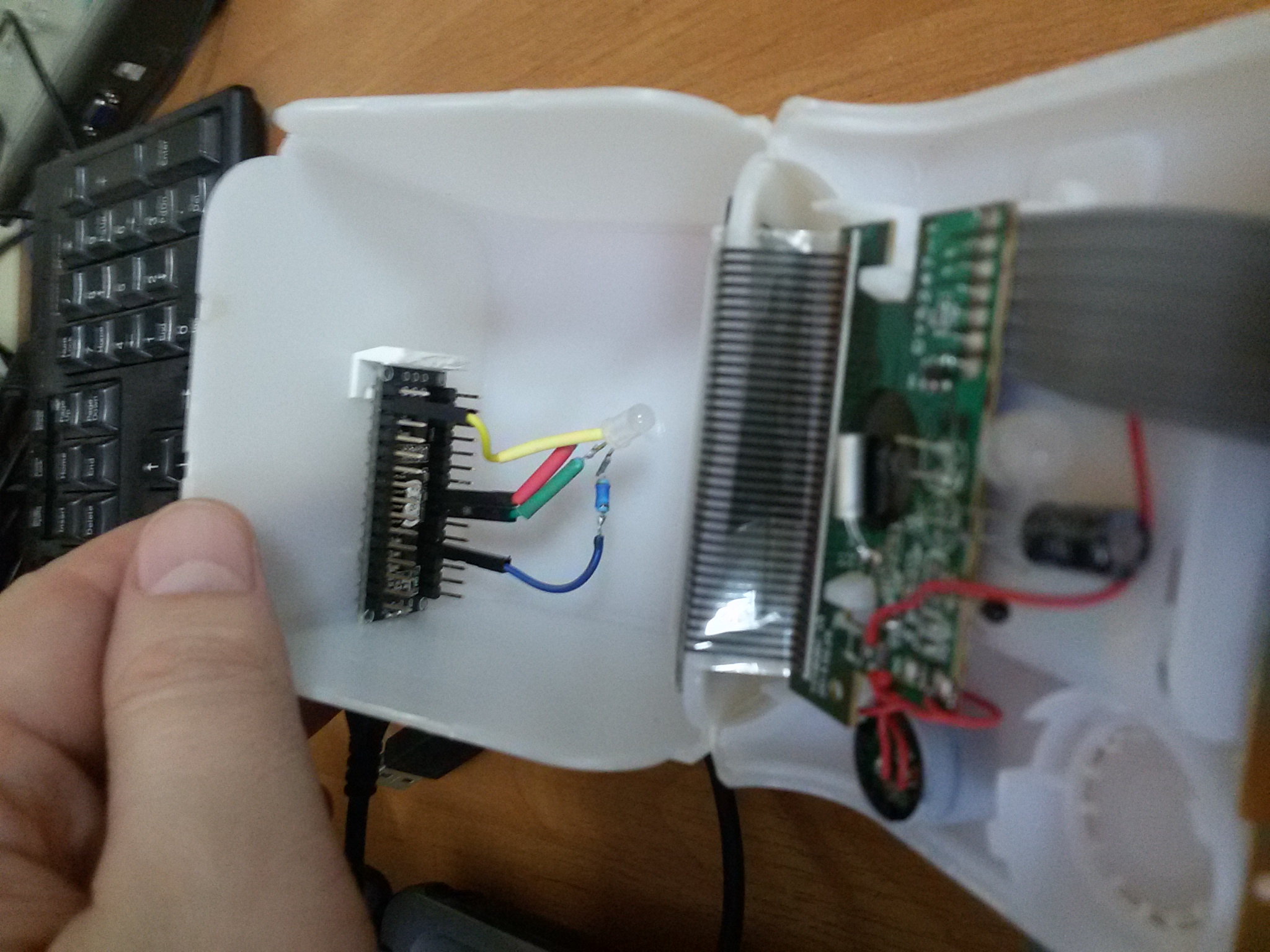
Even easier. Common pin connect with ground (GND). The rest through a 220 Ohm resistor with corresponding pins, as shown in the figure.
Set in a cube, after cutting a hole for the connector.
Software part
It's a little more complicated here. When changing the language, the corresponding value (1 or 2 or 3) should be sent to the COM port.
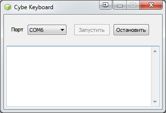
For non-programmers below, there is a link to a Windows program that does this. The only thing in the program you need to specify the COM port to which the Arduino is connected. It is not difficult to find out in the device manager. The program after launching is minimized to tray, but it must be added to the autorun when Windows starts.
The program is written in Delphi, currently does not have:
- Automatic port search functions. This is easy to do, Arduino will send some code at the start, the program will go through the ports and stop if it is read.
- Choice of languages. The program works only with Russian, English and Ukrainian. You can make it possible to specify any language by code.
- Autostart program.
Result
Interestingly, in Windows there is some delay after pressing the language switch combination. In this case, the cube works faster than the indicator, which is very convenient. I have been using this system for more than a year and can’t imagine how to work without it.
If you like the post, I will refine the program by adding the missing functionality described above.
')
Source: https://habr.com/ru/post/357924/
All Articles