Arduino <-> STM32 HAL, or there and back
... and then again there, and again back ... In general, I had quite a lot of “thuds” and “backward”.

I started my GPS Logger project on the Arduino platform . Gradually, I grew to the controller STM32F103 , but the code remained at the base of the Arduin clone - stm32duino. What exactly I am building, why, what libraries I use and other questions about the device itself, I will leave behind the scenes today - I described all this in the mentioned articles (there is a third part about the buildsystem ). Today's topic is moving to HAL (aka STM32Cube).
')
From time to time in the comments to my articles, as well as in personal conversations with colleagues, the question “why arduino? There is a HAL! ”. At first I waved away, they say, I already have the code on the Arduin libraries, I do not want to rewrite. And I did not like HAL because of its ugly and unwieldy style. But the innate curiosity prompted all the same to look once more at HAL from different sides.
I spent several months trying different approaches, libraries and platforms. As a result, I came to the conclusion that HAL, although cumbersome, deserves attention, on the whole. Some things can be achieved with it, which cannot be done using only the Arduino approach (for example, DMA). As a result, I rewrote my project using HAL (not all, the part still remained on the Arduino, but also on top of HAL) about what I want to tell in this article.
So, the architecture that was at the beginning of the work:
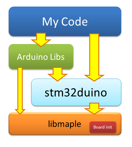
The system layer is implemented by the libmaple library from Leaf Labs. It takes all the work with registers, initialization of the board and other low-level things. The STM32duino library implements the arduino interface and is based on libmaple. Application-level libraries are mainly based on STM32duino, but sometimes they go down to the libmaple level for some custom low-level calls (for example, FreeRTOS works with the SysTick timer).
All this design works pretty well out of the box, many arduino libraries start up with a half kick. Porting my project from classic arduino to stm32duino took only 10 minutes! The stm32duino has quite a larger community, a lot of people graze on the forum and can give competent advice. All code is open, more or less structured, and, theoretically, it can be contributed there (although it takes sooo much time to go from patch to merge).
But there is a nuance. The company Leaf Labs sour the year in 2012 and therefore the library libmaple is supported only by the community (stm32duino community!). On the one hand, there seems to have been licked a bunch of bugs, and the library itself was well optimized, but on the other hand, support for new microcontrollers (as well as new features for the old ones) can wait for a long time.
Whether it is HAL - ST is released itself, there is support for everything that only moves, a convenient graphical configurator STM32CubeMX is available, there is a large (and professional) community. In general, one chocolate! I just didn’t want to throw out all the work and start everything from scratch on HAL. I began to look for the arduino port on top of HAL.
Almost immediately, I stumbled upon the HALMX STM32 . And this is a project from the creators of STM32duino. Just by looking carefully at the code and the forks tree, I realized that it is still very far from a full-fledged framework. Only GPIO and a little more peripherals work. Hope that all the bugs are licked there is meaningless. The authors at the forum confirmed that they just wanted to indulge, tried that this approach was possible. No more.
But the port STM32GENERIC looked more interesting. There was a lot more code there, fresh HAL and CMSIS are flowing in, frequent commits and pull requests into the mainline - all this gave us hope. But these hopes were immediately broken when I tried to compile my project with STM32GENERIC. When assembling, tons of Vorning fell, and in some places it was not compiled at all. Maybe I just did not download it in time?
Having put the props where necessary, I, nevertheless, collected all this gizmo, but, as is usually the case, it did not start - the board simply showed no signs of life. What exactly was not just looking at the code was impossible to understand. In general, I fixed my fixes in STM32GENERIC in pull request and for some time scored. But the awl in one place did not give me rest.
So how does the architecture change with the STM32GENERIC?
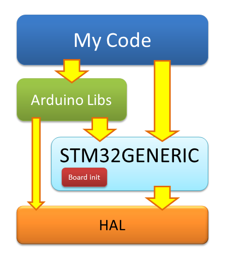
No way! Everything is almost the same. Only instead of libmaple - HAL, instead of stm32duino - STM32GENERIC. Yes, you can write on the arduino framework, flavoring it all with HAL code, but the overall architecture remained the same. I did not like the following moments in it:
I would prefer something like that.

In this scheme, Arduin is assigned only the role of C ++ wrapper over HAL. What is solely to support (implement) the desired interface for the overlying libraries. The board itself is initialized by code that lives in my main () or somewhere nearby. The initialization code runs on top of the HAL and could be mostly generated by CubeMX.
At the expense of libraries. I use NeoGPS (NMEA stream parser) and Adafruit GFX (graphics library + display driver on the SSD1306 controller). These libraries are well written and debugged, they do their job well. I do not see the point of abandoning them and rewriting the client code for something else (which still needs to be tested). I am also in search of a library for working with an SD card. I tried the SD library from the Arduin kit, but it's terrible there. Now I am actively looking towards the SdFat library.
No sooner said than done. Of course, everything and immediately sport on HAL is not possible. But porting on a piece is possible. First, I commented out all the code in my project and turned off all the libraries, leaving only main (). I also commented out the initialization functions of the board from STM32GENERIC and began to gradually copy the necessary things to my main (). As a payload, I added a blinker LED. Pretty quickly, this whole construct was compiled and linked. Only not earned.
What exactly interfered with the work was not obvious. Chinese ST-Link I did not start. It was necessary to look for the cause in some other way. I decided to go the other way - to create a blinker from scratch in CubeMX. Given that the code itself was almost identical, the implementation of the name CubeMX worked, but mine did not. For two nights I reduced one implementation to another, copied the code back and forth. In the end, I was able to start a blinker in my project. I can not say that I found some fundamental problem. Rather, it was a set of small jambs, without which nothing worked
So, the initialization of the board is ready. Most of the code is generated by CubeMX
It's time to take on the periphery. To control the device, I have 2 buttons. Also, I have a status LED, which shows the device status in various blinks.
At first, it turned out to be quite nice (how cute such a bulky code can be). The functional control of the diode moved to its own class.
The mortar itself is trivial and beautiful.
Button handler is easy too
Practice shows that memory consumption must be monitored at each stage. In the current version, the firmware took about 3.5k, of which about 2.5k is HAL (of which almost 2kb is the initialization of the clock). The rest is the initialization code of the board and the interrupt vector.
Too much for “simple wrappers over registers”, but tolerable. If desired, you can enable link time optimization and then the size of the firmware is reduced to 1.8k. The piece is interesting, but the disassembled code becomes almost unreadable. Left as it is at the time of development, this flag can be enabled at the very end, when everything is ready.
But you cannot get far on light bulbs and buttons alone. The next part I decided to uncomment was FreeRTOS. I wanted to tear off my code from STM32GENERIC to the maximum, so I decided to try to screw FreeRTOS from scratch, instead of using a copy of STM32GENERIC - they never know what they were replacing.
After downloading the sources from the FreeRTOS website, I began to screw them according to the instructions . This required to deploy the source, put a couple of files specific to the corresponding platform (port.c and portmacro.h). You also need to remember to set your settings in the configuration file (FreeRTOSConfig.h), and also to declare a couple of handlers of emergency situations in your code (vApplicationStackOverflowHook () and vApplicationMallocFailedHook ()) - they will not be linked without them.
Finally, the final, but the most important stroke, without which nothing will work - interrupt handlers. Probably, it would be correct to declare handlers in my code and make calls to the corresponding FreeRTOS handlers in them, but the STM32GENERIC suggested a simpler way - using defines, substituted the necessary names with ready handlers
FreeRTOS started without any problems, but I was confused by one of the linking works (actually 3 of the same)
Guglezh did not give anything useful. The only more or less relevant advice was to change the alignment in the script of linking certain sections from 4 bytes to 8, but the advice did not help. I went through the entire FreeRTOS platform-specific code using the word align and found it in two pieces of assembly code (just interrupt handlers).
Unfortunately, none of my friends are familiar with the ARM assembler and could not explain the essence of this line. But comparing these pieces with the similar one from stm32duino, I saw that the alignment there was set to 2 bytes, not 4. Yes, there the FreeRTOS version is slightly older, but these pieces of assembly code are identical. Differs only in the .align line. And everything worked there. By changing the alignment to 2 vorning gone and nothing broke. By the way, I will be grateful if someone explains to me the essence of this alignment.
UPD: STM32GENERIC developers proposed another solution
Well, so far everything is going well, but only bulbs and buttons are ready. Now it's time to take on the heavier peripherals - USB, UART, I2C and SPI. I decided to start with USB - the ST-Link debugger (even the real one from Discovery) stubbornly did not want to debug my board, so debugging on prints via USB is the only debugging method available to me. You can, of course, through the UART, but this is a bunch of additional wires.
I went a long way again - I generated the corresponding blanks in the STM32CubeMX, added the USB Middleware from the STM32F1Cube package to my project. You only need to enable USB clocking, define the handlers for the corresponding USB interrupts and polish the little things. For the most part, I copied all the important USB module settings from the STM32GENERIC, except maybe a bit of memory allocation (they used malloc, and I used static distribution).
Here are a couple of interesting pieces that I dragged to myself. For example, in order for a host (computer) to understand that something was connected to it, the device “distorts” the USB D + line (which is connected to pin A12). After seeing such a host, it begins to poll the device for what it is, what interfaces it can, at what speed it wants to communicate, etc. I don’t really understand why this should be done before USB is initialized, but in stm32duino it is done in much the same way.
Another interesting point is the support of the stm32duino bootloader. In order to upload firmware, you must first reboot the controller to the bootloader. The easiest way is to press the reset button. But to make it more convenient, you can learn from the Arduino experience. When thetrees were young AVR controllers did not yet have USB support onboard, there was a USB-UART adapter on the board. The DTR UART signal is connected to the microcontroller reset. When the host sends a DTR signal, the microcontroller is reloaded into the bootloader. Works reinforced!
In the case of USB, we only emulate the COM port. Accordingly, the bootloader needs to be rebooted independently. In addition to the DTR signal, just in case, the stm32duino loader is still waiting for a special magic constant (1EAF - a reference to Leaf Labs)
In general, USB earned. But this layer only works with bytes, not strings. Therefore, debag prints look like this ugly.
Those. there is no support for formatted output at all - neither you need to print a number, nor assemble a string from pieces. The following options appear:
I chose the latter because the Adafruit GFX library code also relies on Print, so I still need to twist it. In addition, the code STM32GENERIC was already at my fingertips.
I created the MiniArduino directory in my project in order to put the minimum amount of code there to implement the arduino interface pieces I needed. I started to copy one file at a time and watch what other dependencies are needed. So I had a copy of the class Print and several strapping files.
But this is not enough. Still, it was necessary to somehow connect the Print class with USB functions (for example, CDC_Transmit_FS ()). For this, I had to draw in the class SerialUSB. He pulled the Stream class and a piece of GPIO initialization. The next step was to connect UART'a (I have a GPS connected to it). So, I also pulled in a SerialUART class, which pulled along another layer of peripheral initialization from STM32GENERIC.
In general, I was in the following situation. I copied almost all the files from STM32GENERIC into my MiniArduino. I also had my own copy of the USB and FreeRTOS libraries (there would have to be more copies of HAL and CMSIS, but I was too lazy). At the same time, I had been trampling on the spot for a month and a half - I connected and disconnected various pieces, but I did not write a single line of new code.
It became clear that my original idea to take control of the entire system part is not very successful. Anyway, part of the initialization code lives in the STM32GENERIC and it looks like it is more comfortable there. Of course, it was possible to break all dependencies and write your own wrapper classes for your tasks, but this would slow me down for another month - this code should also be debugged. Of course, for your own ChSV it would be cool, but you need to move forward!
In general, I threw out all duplicate libraries and almost all of my system layer and returned to STM32GENERIC. This project is developing quite dynamically - several commits per day are stable. In addition, over the past month and a half, I learned a lot, read most of the STM32 Reference Manual, looked at how the HAL libraries and STM32GENERIC wrappers were made, and advanced in understanding USB descriptors and microcontroller peripherals. In general, I was now much more confident in STM32GENERIC than before.
However, my adventures are not over. There was still a UART and I2C (I have a display living there). With the UART, everything was simple enough. I just removed the dynamic memory allocation, and so that the unused UARTs would not eat this very memory, I simply commented out them.
But the implementation of I2C in STM32GENERIC planted kaku. At what very interesting, but which took away from me at least 2 pm. Well, or gave 2 pm hard debag on prints - this is which side to look at.
In general, the implementation of the display did not start. In the already traditional style - that's just not working and everything. What does not work is not clear. The library of the display itself (Adafruit SSD1306) seems to be tested on the previous implementation, but the interference of bugs is not worth excluding. Suspicion falls on HAL and the I2C implementation of STM32GENERIC.
For a start, I commented out all the display code and I2C and wrote I2C initialization without any libraries, on a pure HAL
I set the state of the registers immediately after initialization. I made the same dump in the working version on stm32duino. Here is what I received (with comments to myself)
The first big difference is the 14th bit set in the I2C_OAR1 register. This bit is not described at all in the datasheet and falls into the reserved section. True with the proviso that there still need to write a unit. Those. This is a bug in libmaple. But since everything works there, then this is not the problem. We dig further.
Another difference is the busy bit set. At first, I did not give it any significance, but looking ahead I’ll say it was he who signaled the problem! .. But first things first.
I bungled an initialization code on my knee without any libraries.
After some effort, this code has earned me (in this case, drew stripes). So the problem is in the I2C layer STM32GENERIC. I began to gradually remove my code, replacing it with the appropriate parts from the library. But as soon as I switched the initialization code of the pins from my implementation to the library, the entire transfer on I2C began to fall on timeouts.
Then I remembered the busy bit and tried to understand when it occurs. It turned out that the busy flag occurs as soon as the initialization code turns on the I2c clocking. Those. The module turns on and does not work right away. Interestingly.
Above this code, only initialization pins. Well, what to do - we cover debag prints through the line and there
But bad luck - GPIO_InitStruct is filled correctly. Only mine works, but this one does not. Really, mysticism !!! Everything is like a textbook, but nothing works. I studied the library code line by line in search of at least something suspicious. In the end, I came across this code (it calls the function above)
See the bug in it? And she is! I even removed the extra parameters so that the problem was more visible. In general, the difference is that my code initializes both pins in one structure at once, and the STM32GENERIC code in turn. Apparently, the pin initialization code somehow affects the level on this pin. Until initialization on this pin, nothing is issued and the resistor is pulled up to unity. At the moment of initialization, for some reason, the controller sets zero on the corresponding leg.
This fact is in itself harmless. But the problem is that lowering the SDA line while the SCL line is raised is the start condition for the i2c bus. Because of this, the receiver of the controller goes crazy, sets the BUSY flag and starts to wait for the data. I decided not to gut the library to add the ability to initialize several pins at once. Instead, I just rearranged these 2 lines in places - the initialization of the display was successful. Fix has been adopted in STM32GENERIC .
By the way, the initialization of the bus in libmaple is made interesting. Before starting the initialization of i2c peripherals on the bus, first make a reset. To do this, the library translates pins into the usual GPIO mode and jerks these legs several times, simulating the start and stop sequences. This helps to bring to life the devices stuck on the tire. Unfortunately, there is no similar thing in HAL. Sometimes my display still sticks and then only power off saves.
I was glad to finally return to programming and continue writing features. The next major piece was an SD card connection via SPI. This in itself is an exciting, interesting and painful exercise. I will definitely tell you about it in the next article. One of the problems was the large load (> 50%) of the processor. This called into question the energy efficiency of the device. Yes, and use the device was uncomfortable, because UI was stupid.
Understanding the question, I found the reason for such resource consumption. All work with the SD card was happening byte-by-processor. If it was necessary to write a data block to the card, then the byte send function is called for each byte.
No, well, it's not serious! There is a DMA! Yes, the SD library (the one that comes with Arduino) is clumsy and needs to be changed, but the problem is more global.The same picture is observed in the library working with the screen, and even listening to the UART I have done through a survey. In general, I began to think that rewriting all components on HAL is not such a stupid idea.
I started, of course, with something simpler - the UART driver, which listens to the data stream from the GPS. The Arduino interface does not allow you to cling to the interruption of the UART and snatch incoming characters on the fly. As a result, the only way to get data is a constant survey. Of course, I added vTaskDelay (10) to the GPS handler in order to reduce the load at least a little, but in fact it is a crutch.
The first thought, of course, was to screw the DMA. It would even work if it were not for the NMEA protocol. The problem is that in this protocol the information just goes as a stream, and individual packets (lines) are separated by a newline character. In addition, each line can be a different length. Because of this, it is not known in advance how much data to take. DMA does not work that way - there the number of bytes must be set in advance when forwarding is initiated. In short, DMA disappears, we are looking for another solution.
If you look closely at the design of the NeoGPS library, you can see that the library accepts input data byte-by-byte, but the values are updated only when the entire string arrives (to be more precise, the package consists of several lines). Sono matter what, feed the library bytes one at a time as received, or then all at once. So, you can save CPU time - save the received string to the buffer, while doing this can be done directly in the interrupt. When the string is accepted entirely - you can begin processing.
The following design appears
Although the initialization is lapped from the STM32GENERIC, it is fully consistent with that offered by CubeMX
In fact, the TX pin could not be initialized, but the uartHandle.Init.Mode could be set to UART_MODE_RX - we are only going to accept. However, let it be - suddenly I need to somehow tune the GPS module and write commands to it.
The design of this class could look better if it were not for the limitations of the HAL architecture. So, we can not just set the mode, they say, take everything in a row, directly hook on the interrupt and snatch the received bytes directly from the receiving register. It is necessary to tell HAL in advance how much and where we will receive the byte - the corresponding handlers themselves write the received bytes into the provided buffer. For this, in the last line of the initialization function there is a call HAL_UART_Receive_IT (). Since the length of the string is not known in advance, one has to take one byte.
You also need to announce as many as 2 kolbek. One is the interrupt handler, but its job is just to call the handler from HAL. The second function is “callback” of HAL, that the byte has already been received and it is already in the buffer.
The charReceivedCB () method prepares the HAL to receive the next byte. And it is he who determines that the line has already ended and it is possible to signal this to the main program. As a means of synchronization, it would be possible to use a semaphore in the signal mode, but for such simple purposes it is recommended to use direct notifications.
The response (waiting) function is waitForString (). Its task is simply to hang on the synchronization object and wait (or exit with a timeout)
It works like this.The thread that is responsible for GPS in its normal state is asleep in the waitForString () function. The interrupts coming from the GPS bytes are added to the buffer by the handler. If the \ n (end of line) character arrives, the interrupt wakes up the main thread, which begins to pour bytes from the buffer into the parser. Well, when the parser has finished processing the message packet, it will update the data in the GPS model.
I ran into one very nontrivial moment, at which stuck for several days. It seems like the synchronization code is taken from examples, but at first it did not work - it hung the whole system. I thought that the problem was in direct notifications (functions xTaskNotifyXXX), I redid it into ordinary semaphores, but the application was still hung.
It turned out you need to be very careful with interrupt priority. By default, I set zero (highest) priority to all interrupts. But FreeRTOS has a requirement that priorities be in a given range. Interrupts with too high priority cannot call FreeRTOS functions. Only interrupts with a configLIBRARY_MAX_SYSCALL_INTERRUPT_PRIORITY priority and below can call system functions (a good explanation is at the end of the article and here). This default setting is set to 5. I changed the UART interrupt priority to 6 and everything started up.
Now you can do something more complicated, such as the display driver. But here it is necessary to make an excursion into the theory of the I2C bus. By itself, this bus does not regulate the data transfer protocol on the bus - you can either write bytes or read. You can even write in one transaction, then read (for example, write the address, and then read the data at this address).
However, most devices define a higher level protocol in about the same way. The device provides the user with a set of registers, each with its own address. In this case, in the communication protocol, the first byte (or several) in each transaction determines the address of the cell (register) to which we will continue to read or write. At the same time, multibyte exchange in the style “we will write / read many bytes starting from this address” is also possible. The last option is not bad for DMA.
Unfortunately, the display based on the SSD1306 controller provides a completely different protocol - the command one. The first byte of each transaction is the “command or data” attribute. In the case of a command, the command code is the second byte. If the team needs arguments, they are passed as separate commands after the first one. To initialize the display, you need to send about 30 commands, but they cannot be folded into one array and sent in one block. You need to send them one by one.
But with the sending of an array of pixels (frame buffer) it is quite possible to use the services of DMA. This is what we will try.
Here are just a library Adafruit_SSD1306 written very clumsily and squeeze in there with little blood does not work. Apparently, the library was first written to communicate with the display via SPI. Then someone added support for I2C, and SPI support was left on. Then someone started writing all sorts of low-level optimizations and hiding them behind ifdefs. The result was noodles from the support code of different interfaces. So before you go further you had to comb it.
At first I tried to put it in order, framing the code for different interfaces and defaults. But if I want to write the communication code with the display, use DMA and synchronization via FreeRTOS, then I have very little success. It will be more accurate, but this code will need to be written directly in the library code. So I decidedone more time to upset the library , make the interface and put each driver into a separate class. The code has become cleaner, and one could safely add support for new drivers without changing the library itself.
So let's go.I already showed I2C initialization. Nothing has changed there. But with the sending team a little easier. Remember I talked about the difference between the register and the command protocol for I2C devices? And although the display implements the command protocol, it can be simulated quite well with the help of the register one. You just need to imagine that the display has only 2 registers - 0x00 for commands and 0x40 for data. And HAL even provides a function for this type of transmission.
With the sending of data at first it was not very clear. Source code sent data in small packets of 16 bytes.
I tried to play around with the size of the packets and send in larger packets, but at best I received a broken display. Well, or all hung.
The reason turned out to be trivial - buffer overflow. The wire class from Arduin (in any case, STM32GENERIC) provides its own buffer of only 32 bytes. But why do we even need an additional buffer if the Adafruit_SSD1306 class already has one? Especially with HAL sending turns out in one line
So, half the battle is done - they wrote the driver for the display on a pure HAL. But in this version it is still demanding of resources - 12% of the power for the display 128x32 and 23% for the display 128x64. Using DMA here asks.
To begin, initialize the DMA. We want to implement data transfer in I2C №1, and this function lives on the sixth DMA channel. Initialize byte-wise copying from memory to peripherals
Interrupts are a mandatory part of the design. Otherwise, the HAL_I2C_Mem_Write_DMA () function will start an I2C transaction, but no one will complete it. Again we deal with the bulky design of HAL and the need for as many as two callbacks. Everything is exactly the same as with the UART. One function is an interrupt handler — we simply redirect the call to HAL. The second function is a signal that the data has already gone.
Of course, we will not constantly poll I2C, but has the transfer already ended? Instead, you need to fall asleep on the synchronization object and wait for the transfer to finish.
Data transfer still takes 24 ms - this is almost pure transfer time of 1 kb (display buffer size) at a speed of 400 kHz. Only with this most of the time the processor just sleeps (or does other things). Total CPU utilization dropped from 23% to only 1.5-2%. I think it was worth fighting for this indicator!
In some sense, connecting an SD card via SPI was easier - by that time I began to screw the sdfat library , and there good people had already allocated communication with the card to a separate driver interface. True, with the help of defines, you can choose only one of the 4 ready-made versions of the driver, but this could be easily squandered and substituted for its implementation.
As before, we start with a simple one - with an oak implementation without any DMA. Initialization partially generated by CubeMX, and partly lapped to the SPI implementation of STM32GENERIC
The interface design is sharpened by arduino with numbering of pins with one number. In my case, setting the CS pin through the parameters did not make sense - I have this signal firmly tied to the A4 pin, but I had to follow the interface.
By the design of the SdFat library, the SPI port speed is configured before each transaction. Those.theoretically, you can start communicating with the map at low speed, and then raise it. But I scored this and set the speed once in the begin () method. So the activate / deactivate methods turned out to be empty. Like setSpiSettings ()
CS signal control methods are quite trivial.
We select to the most interesting - reading and writing. The first most oak implementation without DMA
In the SPI interface, data is received and transmitted simultaneously. To accept something you need to send something. Normally, HAL does this for us — we simply call the HAL_SPI_Receive () function and it organizes both sending and receiving. But in fact, this function sends the garbage that was in the receive buffer.
But there is a nuance.SD cards are very capricious. They do not like being shoved by anything that comes when the card sends data. So I had to use the HAL_SPI_TransmitReceive () function and forcibly send 0xffs while receiving data.
Let's take measurements. Let one stream be in a cycle write to the card 1kb of data.
With this approach, in a second it manages to record about 15-16kb. Not much. But it turned out that I put the prescaler on as much as 256. That is, SPI clocking is exposed to much less bandwidth. Experimentally, I found out that the frequency is higher than 9 MHz (the prescaler is set to 8) is meaningless - the recording speed above 100-110 kb / s cannot be achieved (on another flash drive, by the way for some reason only 50-60 kb / s could be recorded, and the third is generally only 40kb / s). Apparently everything depends on the timeout of the flash drive itself.
In principle, this is more than enough, but we are going to pump data through DMA. We act according to the already familiar pattern. First of all initialization. Reception and transmission on SPI live with us on the second and third DMA channels, respectively.
Do not forget to enable interrupts. I will have them with a priority of 8 - slightly lower than that of the UART and I2C
I decided that the overhead of running DMA and synchronization for short transmissions could exceed the gain, because for small packets (up to 16 bytes) I left the old version. Packets longer than 16 bytes are forwarded via DMA. The synchronization method is exactly the same as in the previous section.
Of course, without interruption in any way. It's all the same as in the case of I2C
We start, we check. In order not to torment the flash drive, I decided to debug on reading a large file, and not on the record. Then I found a very interesting point: the reading speed in the non-DMA version was about 250-260 kb / s, whereas with DMA only 5 !!! Moreover, CPU consumption without using DMA was 3%, while with DMA it was 75-80% !!! Those. the result is exactly the opposite of what was expected.
Having logged the driver code almost through a line, I discovered a problem: I used the wrong callback function. Initially, my code used HAL_SPI_Receive_DMA () and together with it the callback HAL_SPI_RxCpltCallback was used in pairs. This design did not work due to the nuance with simultaneous sending of 0xff. When I changed HAL_SPI_Receive_DMA () to HAL_SPI_TransmitReceive_DMA (), it was also necessary to change the callback to HAL_SPI_TxRxCpltCallback (). Those.In fact, the reading took place, but due to the lack of callbacks, the speed was regulated by a timeout of 100ms.
Having repaired the callback, everything fell into place. CPU load dropped to 2.5% (now honest), and the speed even jumped right up to 500kb / s. True, the prescaler had to be put on 4 - with the prescaler on 2 the asserts fell in the SdFat library. It looks like the speed limit of my card.
Unfortunately, this has nothing to do with writing speed. The write speed was still about 50-60kb / s, and the processor load ranged from 60-70%. But digging up the whole evening, and taking measurements in different places, I found out that the actual send () function of my driver (which records one sector of 512 bytes) works in just 1-2ms, including wait and synchronization. Sometimes, however, some timeout is fired and the recording lasts 5-7ms. But the problem is not really in the driver but in the logic of working with the FAT file system.
Rising to the level of files, partitions and clusters, the task of writing 512 to a file is not so trivial. You need to read the FAT table, find a place in it for the recorded sector, write the sector itself, update the records in the FAT table, write these sectors to disk, update the records in the table of files and directories, and a whole bunch of other things. In general, one call to FatFile :: write () could take up to 15-20ms, and a hefty piece of this time is taken by the actual work of the processor for processing records in the file system.
As I have already noted, the CPU usage for writing is 60-70%. But this number also depends on the type of file system (Fat16 or Fat32), the size and, accordingly, the number of these clusters on the partition, the speed of the flash drive, the jammed and fragmented media, the use of long file names and much more. So please treat these measurements as some kind of relative numbers.
With this component came out interesting. In the original implementation of USB Serial from STM32GENERIC there were a number of shortcomings and I undertook to rewrite it for myself. But while I was studying how the USB CDC works, I read the sources and studied the documentation, the guys from STM32GENERIC have significantly improved their implementation. But first things first.
So, the original implementation did not suit me for the following reasons:
For now, let's start with a simple one — synchronous sending of messages, without synchronization and formatting. In fact, the code I honestly slyamzil from STM32GENERIC.
Formally, this is not a synchronous code, since He does not wait for sending data. But this function waits until the previous data is sent. Those.The first call will send the data to the port and exit, but the second call will wait until the data sent on the first call actually goes. In the case of a timeout, data is lost. Also, nothing happens if there is no USB connection at all.
Of course, this is only a blank, because This implementation does not solve the indicated problems. What is needed to make this code asynchronous and non-blocking? Well, at least the buffer. Only when to transfer this buffer?
I think here it is worth making a small excursion into the principles of USB operation. The fact is that the transfer in the USB protocol can only be initiated by the host. If the device needs to transfer data to the host side, the data are prepared in a special PMA (Packet Memory Area) buffer and the device waits until the host picks up this data. The PMC buffer is prepared by the CDC_Transmit_FS () function. This buffer lives inside the USB peripherals, and not in the user code.
I honestly wanted to draw a beautiful picture here, but I never figured out how to display it better.
But it would be great to implement the following scheme. The client code, as necessary, writes data to a cumulative (user) buffer. From time to time the host comes and takes away everything that has accumulated in the buffer by this moment. This is very similar to what I described in the previous paragraph, but there is one key caveat: the data is in the user buffer, not in the PMA. Those.I would like to do without a call to CDC_Transmit_FS (), which pours data from the user buffer into PMA, and instead catch the callback “the host has arrived, the data asks”.
Unfortunately, this approach is not possible in the current USB CDC Middleware design. More precisely, it may be possible, but you need to wedge into the implementation of the CDC driver. I'm still not versed in the USB protocols to do this. In addition, I am not sure that there will be enough USB time limits for such an operation.
Fortunately, at this moment I noticed that STM32GENERIC had already traveled around such a thing. Here is the code I creatively reworked.
The idea behind this code is as follows. Although it was not possible to catch the “host came, wants data” notification, it turned out you can organize a callback “I sent the data to the host, you can pour the following”. Such a double buffer is obtained — while the device is waiting for data to be sent from the internal PMA buffer, the user code can write to the accumulation buffer. When sending data is completed, the cumulative buffer is poured into PMA. It remains only to organize this same callback. For this you need a bit to file the function USBD_CDC_DataIn ()
By the way, the usbDebugWrite function is protected by a mutex and should work correctly from several threads. The USBSerialTransferCompletedCB () function did not protect — it is called from an interrupt and operates with volatile variables. Frankly, somewhere a bug walks here, very rarely symbols are swallowed. But for me this is not critical for debugging. In the “production” code this will not be called.
While this thing can operate only with constant strings. It's time to screw up the analog printf (). I don’t want to use the present printf () function — it pulls the extra kilobyte code for 12 and the heap, which I don’t have. I did find my debug logger, which I once wrote for the AVR. My implementation can print strings as well as numbers in decimal and hexadecimal format. After some doping and testing it turned out something like this:
My implementation is much simpler than the library one, but I can do everything I need to print strings, decimal and hexadecimal numbers with formatting (field width, finishing the number with zeros to the left). It still does not know how to print negative numbers and floating point numbers, but this is easy to add. Later, I may make it possible to write the result to a string buffer (like sprintf), and not just to USB.
The performance of this code is about 150–200 kb / s along with transmission via USB and depends on the number (length) of messages, the complexity of the format string, and also on the size of the buffer. This speed is quite enough to send a couple of thousand small messages per second. Most importantly, calls are not blocking.
In principle, this could have been completed, but I noticed that the guys from STM32GENERIC just recently poured in a new HAL . It is interesting in him that there were a lot of files in the name stm32f1xx_ll_XXXX.h. They found an alternative and lower-level implementation of HAL. Those.the usual HAL provides a fairly high-level interface in the style of “take this array here and pass it to me over this interface. On completion, report an interrupt. ” On the contrary, the files with the letters LL in the name provide a lower-level interface like “set these flags of such and such register”.
Why is this necessary? In most cases, the high-level interface really solves the problem well. HAL (Hardware Abstraction Layer) fully justifies its name - abstracts the code from the processor and hardware registers. But in some cases, HAL limits the flight of the programmer’s imagination, whereas using lower-level abstractions could accomplish the task more effectively. In my case, this is GPIO and UART.
Let's try to touch the new interfaces. Let's start with light bulbs. Unfortunately, there are not enough examples on the Internet. We will try to understand the code comments to the functions, the benefit is all right.
Apparently, these low-level pieces can also be divided into 2 parts:
By default, the first ones are disabled by defining USE_FULL_LL_DRIVER. Well disconnected and to hell with them. We will use the second. After a bit of shamanism, I got this kind of LED driver.
Everything is very simple!The nice thing is that it really works with registers and flags directly. There is no overhead on the module HAL GPIO, which itself compiles as much as 450 bytes, and pin controls from STM32GENERIC, which pulls another 670 bytes. Here, in general, the whole class with all the calls is zailed by the vLEDThread function, the size of which is 48 bytes!
Managing clocking through LL HAL I niasilil. But this is not critical, because calling __HAL_RCC_GPIOC_IS_CLK_ENABLED () from a normal HAL is actually a macro that only sets a couple of flags in certain registers.
With buttons, everything is also simple
With the UART everything will be more interesting. Let me remind you the problem. With HAL, the reception needed to be “recharged” after each received byte. The “take it all” mode is not provided in the HAL. And with LL HAL, everything should work out for us.
Setting the pins made not only ponder, but also look in the Reference Manual
We remake the initialization of UART to new interfaces
Now interrupt. In the past, we had as many as 2 functions - one handled the interrupt, and the second was a callback (from the same interrupt) about the received byte. In the new version, we set up an interrupt only for receiving a byte, so that we receive the received byte immediately.
The size of the driver code has decreased from 1242 to 436 bytes, and the consumption of RAM from 200 to 136 (of which 128 is a buffer). In my opinion not bad. The only pity is that this is not the most voracious part. It would be possible to cut something a little more, but at the moment I don’t particularly chase after the consumption of resources - I still have them. Yes, and the high-level interface HAL in the case of the rest of the periphery works very well.
Although at the start of this project phase I was skeptical about the HAL account, but I still managed to rewrite all the work with peripherals: GPIO, UART, I2C, SPI and USB. I have profoundly advanced the understanding of the work of these modules and tried to convey knowledge in this article. But this is not a translation of the Reference Manual. On the contrary, I worked in the context of this project and showed how to write peripheral drivers in pure HAL.
The article turned out more or less linear history. But in fact, I had a number of brunchs in which I simultaneously sawed in opposite directions. In the morning I could rest against the performance problems of some kind of arduino library and firmly decide to rewrite everything to HAL, and by evening I would find out that someone had already written DMA support in STM32GENERIC and I had a desire to run backwards. Or, for example, a couple of days to butt with arduino interfaces trying to understand how it is more convenient to transmit data on I2C, whereas on the HAL this is done in 2 lines.
In general, I achieved what I wanted. The main work with the periphery is under my control and written in HAL. Arduino also serves only as an adapter for some libraries. True, tails still remained. You still need to get up the courage and remove STM32GENERIC from your repository, leaving only a couple of really useful classes. But this article will not apply to such cleaning.
As for Arudino and its clones. I still like this framework. With it, you can go and look at something that is not really bothering yourself with reading manuals and datasheets. With arduino, in principle, even end devices can be made, if there are no special requirements for speed, power consumption or memory. In my case, these parameters are very important, so I had to move to HAL.
I started working on stm32duino. This clone really deserves attention if you want to have an “arduino” on the STM32 and that everything works out of the box. In addition, there is closely watching the consumption of RAM and flash. By contrast, the STM32GENERIC is thicker in itself and is based on a monstrous HAL. But this framework is actively developing and look more finished. In general, I can recommend both frameworks with a slight preference for STM32GENERIC for HAL and more dynamic development at the moment. In addition, for HAL on the Internet is full of examples and you can always podtyunit something for themselves.
By the very HAL, I still am with a certain degree of disgust. The library is too bulky and ugly. I make a discount on the fact that the library is sishnaya, which causes the use of long-term names of functions and constants. But still this is not the library, work with which brings pleasure. Rather, it is a necessary measure.
Okay interface - insides too make you wonder. Huge functions with functionality for all occasions entail a useless waste of resources. And if with more code in the flash you can fight with the help of link time optimization, then a huge consumption of RAM is treated except by rewriting it on LL HAL.
But even this is not frustrating, but in some places just a devil-may-care attitude to resources. So I noticed a huge memory overhead in the USB Middleware code (formally, this is not HAL, but comes as part of the STM32Cube). Usb structures occupy 2.5kb in memory. The structure of USBD_HandleTypeDef (544 bytes) largely repeats PCD_HandleTypeDef from the bottom layer (1056 bytes) - it also defines endpoints. Transmit / receive buffers are also declared in at least two places - USBD_CDC_HandleTypeDef and UserRxBufferFS / UserTxBufferFS.
Handles are generally declared in RAM. What for?They are constant! Almost 400 bytes in RAM. Fortunately, some of the descriptors are constant (slightly less than 300 bytes). Descriptors are immutable information. And here there is a special code that patches them, and, again, a constant. Yes, and such that there is already inscribed. Functions like SetBuffer for some reason accept a non-constant buffer, which also makes it difficult to put descriptors and some other things in the flash. What is the reason? It is fixed in 10 minutes !!!
Or, the initialization structure is part of the object handle (for example, i2c). Why store it after the periphery is initialized? Why do I need pointers to unused structures - for example, why is the data associated with DMA, if I do not use it?
Special conversion into “Unicode type”, which could be done in the compile time. Yes, and a special buffer for it is selected
Not deadly, but makes you wonder if HAL is as good as apologists write about it? Well, this is not what you expect from the library from the manufacturer and designed for professionals. These are microcontrollers! Here people save every byte and every microsecond is expensive. And here, you understand, the buffer per pound and conversion of constant strings on the fly. It is worth noting that most of the comments to the USB Middleware relate.
UPD: in HAL 1.6 I2C DMA Transfer Completed callback was also broken. Those.there the code disappeared altogether, which in the case of sending data via DMA confirmation generates, although it is described in the documentation. At the reception there, but the transfer is not. I had to move back to HAL 1.4 for the I2C module, the benefit here is one module - one file.
Finally, I will quote the consumption of flush and RAM of various components. In the Drivers section, I gave values for both HAL-based drivers and LL HAL drivers. In the second case, the corresponding sections from the HAL section are not used.
That's all. I would be glad to receive constructive comments, as well as recommendations if anything can be improved here.
I started my GPS Logger project on the Arduino platform . Gradually, I grew to the controller STM32F103 , but the code remained at the base of the Arduin clone - stm32duino. What exactly I am building, why, what libraries I use and other questions about the device itself, I will leave behind the scenes today - I described all this in the mentioned articles (there is a third part about the buildsystem ). Today's topic is moving to HAL (aka STM32Cube).
')
From time to time in the comments to my articles, as well as in personal conversations with colleagues, the question “why arduino? There is a HAL! ”. At first I waved away, they say, I already have the code on the Arduin libraries, I do not want to rewrite. And I did not like HAL because of its ugly and unwieldy style. But the innate curiosity prompted all the same to look once more at HAL from different sides.
I spent several months trying different approaches, libraries and platforms. As a result, I came to the conclusion that HAL, although cumbersome, deserves attention, on the whole. Some things can be achieved with it, which cannot be done using only the Arduino approach (for example, DMA). As a result, I rewrote my project using HAL (not all, the part still remained on the Arduino, but also on top of HAL) about what I want to tell in this article.
Architecture analysis
So, the architecture that was at the beginning of the work:
The system layer is implemented by the libmaple library from Leaf Labs. It takes all the work with registers, initialization of the board and other low-level things. The STM32duino library implements the arduino interface and is based on libmaple. Application-level libraries are mainly based on STM32duino, but sometimes they go down to the libmaple level for some custom low-level calls (for example, FreeRTOS works with the SysTick timer).
All this design works pretty well out of the box, many arduino libraries start up with a half kick. Porting my project from classic arduino to stm32duino took only 10 minutes! The stm32duino has quite a larger community, a lot of people graze on the forum and can give competent advice. All code is open, more or less structured, and, theoretically, it can be contributed there (although it takes sooo much time to go from patch to merge).
But there is a nuance. The company Leaf Labs sour the year in 2012 and therefore the library libmaple is supported only by the community (stm32duino community!). On the one hand, there seems to have been licked a bunch of bugs, and the library itself was well optimized, but on the other hand, support for new microcontrollers (as well as new features for the old ones) can wait for a long time.
Whether it is HAL - ST is released itself, there is support for everything that only moves, a convenient graphical configurator STM32CubeMX is available, there is a large (and professional) community. In general, one chocolate! I just didn’t want to throw out all the work and start everything from scratch on HAL. I began to look for the arduino port on top of HAL.
Almost immediately, I stumbled upon the HALMX STM32 . And this is a project from the creators of STM32duino. Just by looking carefully at the code and the forks tree, I realized that it is still very far from a full-fledged framework. Only GPIO and a little more peripherals work. Hope that all the bugs are licked there is meaningless. The authors at the forum confirmed that they just wanted to indulge, tried that this approach was possible. No more.
But the port STM32GENERIC looked more interesting. There was a lot more code there, fresh HAL and CMSIS are flowing in, frequent commits and pull requests into the mainline - all this gave us hope. But these hopes were immediately broken when I tried to compile my project with STM32GENERIC. When assembling, tons of Vorning fell, and in some places it was not compiled at all. Maybe I just did not download it in time?
Having put the props where necessary, I, nevertheless, collected all this gizmo, but, as is usually the case, it did not start - the board simply showed no signs of life. What exactly was not just looking at the code was impossible to understand. In general, I fixed my fixes in STM32GENERIC in pull request and for some time scored. But the awl in one place did not give me rest.
So how does the architecture change with the STM32GENERIC?
No way! Everything is almost the same. Only instead of libmaple - HAL, instead of stm32duino - STM32GENERIC. Yes, you can write on the arduino framework, flavoring it all with HAL code, but the overall architecture remained the same. I did not like the following moments in it:
- The initialization of the board (a piece in the scheme called board init) and main () is in STM32GENERIC. In most cases, this is more than enough. But I plan to use various energy-saving modes, and for this you need to be able to correctly manage the clocking and initialization of the controller. The exit from some modes implies the MK core reset, which means I need to be closer to this reset.
- I would like my device to simultaneously implement a USB CDC (virtual COM port) and a Mass Storage Class Device. In the STM32GENERIC implementation, the USB layer is buried deep enough and implements either the CDC or the MSC (switches by define), whereas I would like to have more control over this piece in order to implement both interfaces simultaneously.
- Finally, arduino is like a Swiss knife - it is inferior to individual specialized tools, but it is universal. As a consequence, we have a bunch of code that is present there just in case. For example, the GPIO control code contains references to ADCs, timers, and PWM simply because arduino pins can perform these functions. At me all periphery is in advance distributed and can be initialized more effectively.
I would prefer something like that.
In this scheme, Arduin is assigned only the role of C ++ wrapper over HAL. What is solely to support (implement) the desired interface for the overlying libraries. The board itself is initialized by code that lives in my main () or somewhere nearby. The initialization code runs on top of the HAL and could be mostly generated by CubeMX.
At the expense of libraries. I use NeoGPS (NMEA stream parser) and Adafruit GFX (graphics library + display driver on the SSD1306 controller). These libraries are well written and debugged, they do their job well. I do not see the point of abandoning them and rewriting the client code for something else (which still needs to be tested). I am also in search of a library for working with an SD card. I tried the SD library from the Arduin kit, but it's terrible there. Now I am actively looking towards the SdFat library.
There: Initialization of the board
No sooner said than done. Of course, everything and immediately sport on HAL is not possible. But porting on a piece is possible. First, I commented out all the code in my project and turned off all the libraries, leaving only main (). I also commented out the initialization functions of the board from STM32GENERIC and began to gradually copy the necessary things to my main (). As a payload, I added a blinker LED. Pretty quickly, this whole construct was compiled and linked. Only not earned.
What exactly interfered with the work was not obvious. Chinese ST-Link I did not start. It was necessary to look for the cause in some other way. I decided to go the other way - to create a blinker from scratch in CubeMX. Given that the code itself was almost identical, the implementation of the name CubeMX worked, but mine did not. For two nights I reduced one implementation to another, copied the code back and forth. In the end, I was able to start a blinker in my project. I can not say that I found some fundamental problem. Rather, it was a set of small jambs, without which nothing worked
- The flash start address was incorrectly forwarded from the project settings to the code. This is important because The first 8kb flash takes the bootloader, so the interrupt controller needs to say that the vector table has moved a bit.
- The interrupt handlers lived in my .cpp files, but I forgot to tell them extern “C”. Without this, the functions were differently different and did not overlap the corresponding weak functions from HAL.
- Some code was superfluous, somewhere, on the contrary, some trifles were missing
So, the initialization of the board is ready. Most of the code is generated by CubeMX
Initialization Board
// Set up board clocks void SystemClock_Config(void) { // Set up external oscillator to 72 MHz RCC_OscInitTypeDef RCC_OscInitStruct; RCC_OscInitStruct.OscillatorType = RCC_OSCILLATORTYPE_HSE; RCC_OscInitStruct.HSEState = RCC_HSE_ON; RCC_OscInitStruct.LSEState = RCC_LSE_OFF; RCC_OscInitStruct.HSIState = RCC_HSI_ON; RCC_OscInitStruct.HSICalibrationValue = 16; RCC_OscInitStruct.HSEPredivValue = RCC_HSE_PREDIV_DIV1; RCC_OscInitStruct.PLL.PLLState = RCC_PLL_ON; RCC_OscInitStruct.PLL.PLLSource = RCC_PLLSOURCE_HSE; RCC_OscInitStruct.PLL.PLLMUL = RCC_PLL_MUL9; HAL_RCC_OscConfig(&RCC_OscInitStruct); // Set up periperal clocking RCC_ClkInitTypeDef RCC_ClkInitStruct; RCC_ClkInitStruct.ClockType = RCC_CLOCKTYPE_HCLK|RCC_CLOCKTYPE_SYSCLK |RCC_CLOCKTYPE_PCLK1|RCC_CLOCKTYPE_PCLK2; RCC_ClkInitStruct.SYSCLKSource = RCC_SYSCLKSOURCE_PLLCLK; RCC_ClkInitStruct.AHBCLKDivider = RCC_SYSCLK_DIV1; RCC_ClkInitStruct.APB1CLKDivider = RCC_HCLK_DIV2; RCC_ClkInitStruct.APB2CLKDivider = RCC_HCLK_DIV1; HAL_RCC_ClockConfig(&RCC_ClkInitStruct, FLASH_LATENCY_2); // Set up USB clock RCC_PeriphCLKInitTypeDef PeriphClkInit; PeriphClkInit.PeriphClockSelection = RCC_PERIPHCLK_USB; PeriphClkInit.UsbClockSelection = RCC_USBCLKSOURCE_PLL_DIV1_5; HAL_RCCEx_PeriphCLKConfig(&PeriphClkInit); // Set up SysTTick to 1 ms // TODO: Do we really need this? SysTick is initialized multiple times in HAL HAL_SYSTICK_Config(HAL_RCC_GetHCLKFreq()/1000); HAL_SYSTICK_CLKSourceConfig(SYSTICK_CLKSOURCE_HCLK); // SysTick_IRQn interrupt configuration HAL_NVIC_SetPriority(SysTick_IRQn, 0, 0); } // Handle SysTick timer extern "C" void SysTick_Handler(void) { HAL_IncTick(); HAL_SYSTICK_IRQHandler(); } void InitBoard() { // Initialize board and HAL HAL_Init(); SystemClock_Config(); HAL_NVIC_SetPriorityGrouping(NVIC_PRIORITYGROUP_4); } There: light bulbs and buttons
It's time to take on the periphery. To control the device, I have 2 buttons. Also, I have a status LED, which shows the device status in various blinks.
At first, it turned out to be quite nice (how cute such a bulky code can be). The functional control of the diode moved to its own class.
LED driver
#define LED_PORT GPIOC const uint16_t LED_PIN = GPIO_PIN_13; // Class to encapsulate working with onboard LED(s) // // Note: this class initializes corresponding pins in the constructor. // May not be working properly if objects of this class are created as global variables class LEDDriver { public: LEDDriver() { // enable clock to GPIOC __HAL_RCC_GPIOC_CLK_ENABLE(); // Turn off the LED by default HAL_GPIO_WritePin(LED_PORT, LED_PIN, GPIO_PIN_SET); // Initialize PC13 pin GPIO_InitTypeDef ledPinInit; ledPinInit.Pin = LED_PIN; ledPinInit.Mode = GPIO_MODE_OUTPUT_PP; ledPinInit.Speed = GPIO_SPEED_FREQ_LOW; HAL_GPIO_Init(LED_PORT, &ledPinInit); } void turnOn() { HAL_GPIO_WritePin(LED_PORT, LED_PIN, GPIO_PIN_RESET); } void turnOff() { HAL_GPIO_WritePin(LED_PORT, LED_PIN, GPIO_PIN_SET); } void toggle() { HAL_GPIO_TogglePin(LED_PORT, LED_PIN); } }; The mortar itself is trivial and beautiful.
Twinkle
int main(void) { InitBoard(); LEDDriver led; while(1) { HAL_Delay(500); led.toggle(); } } Button handler is easy too
Driver buttons
// Pins assignment #define BUTTONS_PORT GPIOC const uint16_t SEL_BUTTON_PIN = GPIO_PIN_14; const uint16_t OK_BUTTON_PIN = GPIO_PIN_15; // Initialize buttons related stuff void initButtons() { // enable clock to GPIOC __HAL_RCC_GPIOC_CLK_ENABLE(); // Initialize button pins GPIO_InitTypeDef pinInit; pinInit.Mode = GPIO_MODE_INPUT; pinInit.Pull = GPIO_PULLDOWN; pinInit.Speed = GPIO_SPEED_FREQ_LOW; pinInit.Pin = SEL_BUTTON_PIN | OK_BUTTON_PIN; HAL_GPIO_Init(BUTTONS_PORT, &pinInit); … } // Reading button state (perform debounce first) inline bool getButtonState(uint16_t pin) { if(HAL_GPIO_ReadPin(BUTTONS_PORT, pin)) { // dobouncing vTaskDelay(DEBOUNCE_DURATION); if(HAL_GPIO_ReadPin(BUTTONS_PORT, pin)) return true; } return false; } Practice shows that memory consumption must be monitored at each stage. In the current version, the firmware took about 3.5k, of which about 2.5k is HAL (of which almost 2kb is the initialization of the clock). The rest is the initialization code of the board and the interrupt vector.
Too much for “simple wrappers over registers”, but tolerable. If desired, you can enable link time optimization and then the size of the firmware is reduced to 1.8k. The piece is interesting, but the disassembled code becomes almost unreadable. Left as it is at the time of development, this flag can be enabled at the very end, when everything is ready.
There: FreeRTOS
But you cannot get far on light bulbs and buttons alone. The next part I decided to uncomment was FreeRTOS. I wanted to tear off my code from STM32GENERIC to the maximum, so I decided to try to screw FreeRTOS from scratch, instead of using a copy of STM32GENERIC - they never know what they were replacing.
After downloading the sources from the FreeRTOS website, I began to screw them according to the instructions . This required to deploy the source, put a couple of files specific to the corresponding platform (port.c and portmacro.h). You also need to remember to set your settings in the configuration file (FreeRTOSConfig.h), and also to declare a couple of handlers of emergency situations in your code (vApplicationStackOverflowHook () and vApplicationMallocFailedHook ()) - they will not be linked without them.
Finally, the final, but the most important stroke, without which nothing will work - interrupt handlers. Probably, it would be correct to declare handlers in my code and make calls to the corresponding FreeRTOS handlers in them, but the STM32GENERIC suggested a simpler way - using defines, substituted the necessary names with ready handlers
/* Definitions that map the FreeRTOS port interrupt handlers to their CMSIS standard names. */ #define vPortSVCHandler SVC_Handler #define xPortPendSVHandler PendSV_Handler #define xPortSysTickHandler HAL_SYSTICK_Callback FreeRTOS started without any problems, but I was confused by one of the linking works (actually 3 of the same)
ld.exe: warning: changing start of section .text by 4 bytesGuglezh did not give anything useful. The only more or less relevant advice was to change the alignment in the script of linking certain sections from 4 bytes to 8, but the advice did not help. I went through the entire FreeRTOS platform-specific code using the word align and found it in two pieces of assembly code (just interrupt handlers).
Interrupt handler
void vPortSVCHandler( void ) { __asm volatile ( " ldr r3, pxCurrentTCBConst2 \n" /* Restore the context. */ " ldr r1, [r3] \n" /* Use pxCurrentTCBConst to get the pxCurrentTCB address. */ " ldr r0, [r1] \n" /* The first item in pxCurrentTCB is the task top of stack. */ " ldmia r0!, {r4-r11} \n" /* Pop the registers that are not automatically saved on exception entry and the critical nesting count. */ " msr psp, r0 \n" /* Restore the task stack pointer. */ " isb \n" " mov r0, #0 \n" " msr basepri, r0 \n" " orr r14, #0xd \n" " bx r14 \n" " \n" " .align 4 \n" "pxCurrentTCBConst2: .word pxCurrentTCB \n" ); } Unfortunately, none of my friends are familiar with the ARM assembler and could not explain the essence of this line. But comparing these pieces with the similar one from stm32duino, I saw that the alignment there was set to 2 bytes, not 4. Yes, there the FreeRTOS version is slightly older, but these pieces of assembly code are identical. Differs only in the .align line. And everything worked there. By changing the alignment to 2 vorning gone and nothing broke. By the way, I will be grateful if someone explains to me the essence of this alignment.
UPD: STM32GENERIC developers proposed another solution
There: USB
Well, so far everything is going well, but only bulbs and buttons are ready. Now it's time to take on the heavier peripherals - USB, UART, I2C and SPI. I decided to start with USB - the ST-Link debugger (even the real one from Discovery) stubbornly did not want to debug my board, so debugging on prints via USB is the only debugging method available to me. You can, of course, through the UART, but this is a bunch of additional wires.
I went a long way again - I generated the corresponding blanks in the STM32CubeMX, added the USB Middleware from the STM32F1Cube package to my project. You only need to enable USB clocking, define the handlers for the corresponding USB interrupts and polish the little things. For the most part, I copied all the important USB module settings from the STM32GENERIC, except maybe a bit of memory allocation (they used malloc, and I used static distribution).
Here are a couple of interesting pieces that I dragged to myself. For example, in order for a host (computer) to understand that something was connected to it, the device “distorts” the USB D + line (which is connected to pin A12). After seeing such a host, it begins to poll the device for what it is, what interfaces it can, at what speed it wants to communicate, etc. I don’t really understand why this should be done before USB is initialized, but in stm32duino it is done in much the same way.
USB jitter
USBD_HandleTypeDef hUsbDeviceFS; void Reenumerate() { // Initialize PA12 pin GPIO_InitTypeDef pinInit; pinInit.Pin = GPIO_PIN_12; pinInit.Mode = GPIO_MODE_OUTPUT_PP; pinInit.Speed = GPIO_SPEED_FREQ_LOW; HAL_GPIO_Init(GPIOA, &pinInit); // Let host know to enumerate USB devices on the bus HAL_GPIO_WritePin(GPIOA, GPIO_PIN_12, GPIO_PIN_RESET); for(unsigned int i=0; i<512; i++) {}; // Restore pin mode pinInit.Mode = GPIO_MODE_INPUT; pinInit.Pull = GPIO_NOPULL; HAL_GPIO_Init(GPIOA, &pinInit); for(unsigned int i=0; i<512; i++) {}; } void initUSB() { Reenumerate(); USBD_Init(&hUsbDeviceFS, &FS_Desc, DEVICE_FS); USBD_RegisterClass(&hUsbDeviceFS, &USBD_CDC); USBD_CDC_RegisterInterface(&hUsbDeviceFS, &USBD_Interface_fops_FS); USBD_Start(&hUsbDeviceFS); } Another interesting point is the support of the stm32duino bootloader. In order to upload firmware, you must first reboot the controller to the bootloader. The easiest way is to press the reset button. But to make it more convenient, you can learn from the Arduino experience. When the
In the case of USB, we only emulate the COM port. Accordingly, the bootloader needs to be rebooted independently. In addition to the DTR signal, just in case, the stm32duino loader is still waiting for a special magic constant (1EAF - a reference to Leaf Labs)
Reboot to bootloader
static int8_t CDC_Control_FS (uint8_t cmd, uint8_t* pbuf, uint16_t length) { ... case CDC_SET_CONTROL_LINE_STATE: dtr_pin++; //DTR pin is enabled break; ... static int8_t CDC_Receive_FS (uint8_t* Buf, uint32_t *Len) { /* Four byte is the magic pack "1EAF" that puts the MCU into bootloader. */ if(*Len >= 4) { /** * Check if the incoming contains the string "1EAF". * If yes, check if the DTR has been set, to put the MCU into the bootloader mode. */ if(dtr_pin > 3) { if((Buf[0] == '1')&&(Buf[1] == 'E')&&(Buf[2] == 'A')&&(Buf[3] == 'F')) { HAL_NVIC_SystemReset(); } dtr_pin = 0; } } ... } Back: MiniArduino
In general, USB earned. But this layer only works with bytes, not strings. Therefore, debag prints look like this ugly.
CDC_Transmit_FS((uint8_t*)"Ping\n", 5); // 5 is a strlen(“Ping”) + zero byte Those. there is no support for formatted output at all - neither you need to print a number, nor assemble a string from pieces. The following options appear:
- Fasten the classic printf. The option seems to be quite good, but pulls on + 12kb of firmware (I already somehow accidentally called sprintf in myself)
- Digging out your own printf implementation in your storeroom. I once wrote something under AVR, like this implementation was smaller.
- Screw the class Print from arduino in the implementation of STM32GENERIC
I chose the latter because the Adafruit GFX library code also relies on Print, so I still need to twist it. In addition, the code STM32GENERIC was already at my fingertips.
I created the MiniArduino directory in my project in order to put the minimum amount of code there to implement the arduino interface pieces I needed. I started to copy one file at a time and watch what other dependencies are needed. So I had a copy of the class Print and several strapping files.
But this is not enough. Still, it was necessary to somehow connect the Print class with USB functions (for example, CDC_Transmit_FS ()). For this, I had to draw in the class SerialUSB. He pulled the Stream class and a piece of GPIO initialization. The next step was to connect UART'a (I have a GPS connected to it). So, I also pulled in a SerialUART class, which pulled along another layer of peripheral initialization from STM32GENERIC.
In general, I was in the following situation. I copied almost all the files from STM32GENERIC into my MiniArduino. I also had my own copy of the USB and FreeRTOS libraries (there would have to be more copies of HAL and CMSIS, but I was too lazy). At the same time, I had been trampling on the spot for a month and a half - I connected and disconnected various pieces, but I did not write a single line of new code.
It became clear that my original idea to take control of the entire system part is not very successful. Anyway, part of the initialization code lives in the STM32GENERIC and it looks like it is more comfortable there. Of course, it was possible to break all dependencies and write your own wrapper classes for your tasks, but this would slow me down for another month - this code should also be debugged. Of course, for your own ChSV it would be cool, but you need to move forward!
In general, I threw out all duplicate libraries and almost all of my system layer and returned to STM32GENERIC. This project is developing quite dynamically - several commits per day are stable. In addition, over the past month and a half, I learned a lot, read most of the STM32 Reference Manual, looked at how the HAL libraries and STM32GENERIC wrappers were made, and advanced in understanding USB descriptors and microcontroller peripherals. In general, I was now much more confident in STM32GENERIC than before.
Back: I2C
However, my adventures are not over. There was still a UART and I2C (I have a display living there). With the UART, everything was simple enough. I just removed the dynamic memory allocation, and so that the unused UARTs would not eat this very memory, I simply commented out them.
But the implementation of I2C in STM32GENERIC planted kaku. At what very interesting, but which took away from me at least 2 pm. Well, or gave 2 pm hard debag on prints - this is which side to look at.
In general, the implementation of the display did not start. In the already traditional style - that's just not working and everything. What does not work is not clear. The library of the display itself (Adafruit SSD1306) seems to be tested on the previous implementation, but the interference of bugs is not worth excluding. Suspicion falls on HAL and the I2C implementation of STM32GENERIC.
For a start, I commented out all the display code and I2C and wrote I2C initialization without any libraries, on a pure HAL
I2C Initialization
GPIO_InitTypeDef GPIO_InitStruct; GPIO_InitStruct.Pin = GPIO_PIN_6|GPIO_PIN_7; GPIO_InitStruct.Mode = GPIO_MODE_AF_OD; GPIO_InitStruct.Pull = GPIO_PULLUP; GPIO_InitStruct.Speed = GPIO_SPEED_HIGH; HAL_GPIO_Init(GPIOB, &GPIO_InitStruct); __I2C1_CLK_ENABLE(); hi2c1.Instance = I2C1; hi2c1.Init.ClockSpeed = 400000; hi2c1.Init.DutyCycle = I2C_DUTYCYCLE_2; hi2c1.Init.OwnAddress1 = 0; hi2c1.Init.AddressingMode = I2C_ADDRESSINGMODE_7BIT; hi2c1.Init.DualAddressMode = I2C_DUALADDRESS_DISABLED; hi2c1.Init.OwnAddress2 = 0; hi2c1.Init.GeneralCallMode = I2C_GENERALCALL_DISABLED; hi2c1.Init.NoStretchMode = I2C_NOSTRETCH_DISABLED; HAL_I2C_Init(&hi2c1); I set the state of the registers immediately after initialization. I made the same dump in the working version on stm32duino. Here is what I received (with comments to myself)
Good (Stm32duino):
40005400: 0 0 0 1 - I2C_CR1: Peripheral enable
40005404: 0 0 1 24 - I2C_CR2: Error interrupt enabled, 36Mhz
40005408: 0 0 0 0 - I2C_OAR1: zero own address
4000540C: 0 0 0 0 - I2C_OAR2: Own address register
40005410: 0 0 0 AF - I2C_DR: data register
40005414: 0 0 0 0 - I2C_SR1: status register
40005418: 0 0 0 0 - I2C_SR2: status register
4000541C: 0 0 80 1E - I2C_CCR: 400kHz mode
40005420: 0 0 0 B - I2C_TRISE

Bad (STM32GENERIC):
40005400: 0 0 0 1 - I2C_CR1: Peripheral enable
40005404: 0 0 0 24 - I2C_CR2: 36Mhz
40005408: 0 0 40 0 - I2C_OAR1: !!! Not described bit in address register set
4000540C: 0 0 0 0 - I2C_OAR2: Own address register
40005410: 0 0 0 0 - I2C_DR: data register
40005414: 0 0 0 0 - I2C_SR1: status register
40005418: 0 0 0 2 - I2C_SR2: busy bit set
4000541C: 0 0 80 1E - I2C_CCR: 400kHz mode
40005420: 0 0 0 B - I2C_TRISE
The first big difference is the 14th bit set in the I2C_OAR1 register. This bit is not described at all in the datasheet and falls into the reserved section. True with the proviso that there still need to write a unit. Those. This is a bug in libmaple. But since everything works there, then this is not the problem. We dig further.
Another difference is the busy bit set. At first, I did not give it any significance, but looking ahead I’ll say it was he who signaled the problem! .. But first things first.
I bungled an initialization code on my knee without any libraries.
Display initialization
void sendCommand(I2C_HandleTypeDef * handle, uint8_t cmd) { SerialUSB.print("Sending command "); SerialUSB.println(cmd, 16); uint8_t xBuffer[2]; xBuffer[0] = 0x00; xBuffer[1] = cmd; HAL_I2C_Master_Transmit(handle, I2C1_DEVICE_ADDRESS<<1, xBuffer, 2, 10); } ... sendCommand(handle, SSD1306_DISPLAYOFF); sendCommand(handle, SSD1306_SETDISPLAYCLOCKDIV); // 0xD5 sendCommand(handle, 0x80); // the suggested ratio 0x80 sendCommand(handle, SSD1306_SETMULTIPLEX); // 0xA8 sendCommand(handle, 0x3F); sendCommand(handle, SSD1306_SETDISPLAYOFFSET); // 0xD3 sendCommand(handle, 0x0); // no offset sendCommand(handle, SSD1306_SETSTARTLINE | 0x0); // line #0 sendCommand(handle, SSD1306_CHARGEPUMP); // 0x8D sendCommand(handle, 0x14); sendCommand(handle, SSD1306_MEMORYMODE); // 0x20 sendCommand(handle, 0x00); // 0x0 act like ks0108 sendCommand(handle, SSD1306_SEGREMAP | 0x1); sendCommand(handle, SSD1306_COMSCANDEC); sendCommand(handle, SSD1306_SETCOMPINS); // 0xDA sendCommand(handle, 0x12); sendCommand(handle, SSD1306_SETCONTRAST); // 0x81 sendCommand(handle, 0xCF); sendCommand(handle, SSD1306_SETPRECHARGE); // 0xd9 sendCommand(handle, 0xF1); sendCommand(handle, SSD1306_SETVCOMDETECT); // 0xDB sendCommand(handle, 0x40); sendCommand(handle, SSD1306_DISPLAYALLON_RESUME); // 0xA4 sendCommand(handle, SSD1306_DISPLAYON); // 0xA6 sendCommand(handle, SSD1306_NORMALDISPLAY); // 0xA6 sendCommand(handle, SSD1306_INVERTDISPLAY); sendCommand(handle, SSD1306_COLUMNADDR); sendCommand(handle, 0); // Column start address (0 = reset) sendCommand(handle, SSD1306_LCDWIDTH-1); // Column end address (127 = reset) sendCommand(handle, SSD1306_PAGEADDR); sendCommand(handle, 0); // Page start address (0 = reset) sendCommand(handle, 7); // Page end address uint8_t buf[17]; buf[0] = 0x40; for(uint8_t x=1; x<17; x++) buf[x] = 0xf0; // 4 black, 4 white lines for (uint16_t i=0; i<(SSD1306_LCDWIDTH*SSD1306_LCDHEIGHT/8); i++) { HAL_I2C_Master_Transmit(handle, I2C1_DEVICE_ADDRESS<<1, buf, 17, 10); } After some effort, this code has earned me (in this case, drew stripes). So the problem is in the I2C layer STM32GENERIC. I began to gradually remove my code, replacing it with the appropriate parts from the library. But as soon as I switched the initialization code of the pins from my implementation to the library, the entire transfer on I2C began to fall on timeouts.
Then I remembered the busy bit and tried to understand when it occurs. It turned out that the busy flag occurs as soon as the initialization code turns on the I2c clocking. Those. The module turns on and does not work right away. Interestingly.
We fall on the initialization
uint8_t * pv = (uint8_t*)0x40005418; //I2C_SR2 register. Looking for BUSY flag SerialUSB.print("40005418 = "); SerialUSB.println(*pv, 16); // Prints 0 __HAL_RCC_I2C1_CLK_ENABLE(); SerialUSB.print("40005418 = "); SerialUSB.println(*pv, 16); // Prints 2 Above this code, only initialization pins. Well, what to do - we cover debag prints through the line and there
STM32GENERIC pin initialization
void stm32AfInit(const stm32_af_pin_list_type list[], int size, const void *instance, GPIO_TypeDef *port, uint32_t pin, uint32_t mode, uint32_t pull) { … GPIO_InitTypeDef GPIO_InitStruct; GPIO_InitStruct.Pin = pin; GPIO_InitStruct.Mode = mode; GPIO_InitStruct.Pull = pull; GPIO_InitStruct.Speed = GPIO_SPEED_FREQ_VERY_HIGH; HAL_GPIO_Init(port, &GPIO_InitStruct); … } But bad luck - GPIO_InitStruct is filled correctly. Only mine works, but this one does not. Really, mysticism !!! Everything is like a textbook, but nothing works. I studied the library code line by line in search of at least something suspicious. In the end, I came across this code (it calls the function above)
Another piece of initialization
void stm32AfI2CInit(const I2C_TypeDef *instance, …) { stm32AfInit(chip_af_i2c_sda, …); stm32AfInit(chip_af_i2c_scl, …); } See the bug in it? And she is! I even removed the extra parameters so that the problem was more visible. In general, the difference is that my code initializes both pins in one structure at once, and the STM32GENERIC code in turn. Apparently, the pin initialization code somehow affects the level on this pin. Until initialization on this pin, nothing is issued and the resistor is pulled up to unity. At the moment of initialization, for some reason, the controller sets zero on the corresponding leg.
This fact is in itself harmless. But the problem is that lowering the SDA line while the SCL line is raised is the start condition for the i2c bus. Because of this, the receiver of the controller goes crazy, sets the BUSY flag and starts to wait for the data. I decided not to gut the library to add the ability to initialize several pins at once. Instead, I just rearranged these 2 lines in places - the initialization of the display was successful. Fix has been adopted in STM32GENERIC .
By the way, the initialization of the bus in libmaple is made interesting. Before starting the initialization of i2c peripherals on the bus, first make a reset. To do this, the library translates pins into the usual GPIO mode and jerks these legs several times, simulating the start and stop sequences. This helps to bring to life the devices stuck on the tire. Unfortunately, there is no similar thing in HAL. Sometimes my display still sticks and then only power off saves.
I2c initialization from stm32duino
/** * @brief Reset an I2C bus. * * Reset is accomplished by clocking out pulses until any hung slaves * release SDA and SCL, then generating a START condition, then a STOP * condition. * * @param dev I2C device */ void i2c_bus_reset(const i2c_dev *dev) { /* Release both lines */ i2c_master_release_bus(dev); /* * Make sure the bus is free by clocking it until any slaves release the * bus. */ while (!gpio_read_bit(sda_port(dev), dev->sda_pin)) { /* Wait for any clock stretching to finish */ while (!gpio_read_bit(scl_port(dev), dev->scl_pin)) ; delay_us(10); /* Pull low */ gpio_write_bit(scl_port(dev), dev->scl_pin, 0); delay_us(10); /* Release high again */ gpio_write_bit(scl_port(dev), dev->scl_pin, 1); delay_us(10); } /* Generate start then stop condition */ gpio_write_bit(sda_port(dev), dev->sda_pin, 0); delay_us(10); gpio_write_bit(scl_port(dev), dev->scl_pin, 0); delay_us(10); gpio_write_bit(scl_port(dev), dev->scl_pin, 1); delay_us(10); gpio_write_bit(sda_port(dev), dev->sda_pin, 1); } Again there: UART
I was glad to finally return to programming and continue writing features. The next major piece was an SD card connection via SPI. This in itself is an exciting, interesting and painful exercise. I will definitely tell you about it in the next article. One of the problems was the large load (> 50%) of the processor. This called into question the energy efficiency of the device. Yes, and use the device was uncomfortable, because UI was stupid.
Understanding the question, I found the reason for such resource consumption. All work with the SD card was happening byte-by-processor. If it was necessary to write a data block to the card, then the byte send function is called for each byte.
for (uint16_t i = 0; i < 512; i++) { spiSend(src[i]); No, well, it's not serious! There is a DMA! Yes, the SD library (the one that comes with Arduino) is clumsy and needs to be changed, but the problem is more global.The same picture is observed in the library working with the screen, and even listening to the UART I have done through a survey. In general, I began to think that rewriting all components on HAL is not such a stupid idea.
I started, of course, with something simpler - the UART driver, which listens to the data stream from the GPS. The Arduino interface does not allow you to cling to the interruption of the UART and snatch incoming characters on the fly. As a result, the only way to get data is a constant survey. Of course, I added vTaskDelay (10) to the GPS handler in order to reduce the load at least a little, but in fact it is a crutch.
The first thought, of course, was to screw the DMA. It would even work if it were not for the NMEA protocol. The problem is that in this protocol the information just goes as a stream, and individual packets (lines) are separated by a newline character. In addition, each line can be a different length. Because of this, it is not known in advance how much data to take. DMA does not work that way - there the number of bytes must be set in advance when forwarding is initiated. In short, DMA disappears, we are looking for another solution.
If you look closely at the design of the NeoGPS library, you can see that the library accepts input data byte-by-byte, but the values are updated only when the entire string arrives (to be more precise, the package consists of several lines). Sono matter what, feed the library bytes one at a time as received, or then all at once. So, you can save CPU time - save the received string to the buffer, while doing this can be done directly in the interrupt. When the string is accepted entirely - you can begin processing.
The following design appears
UART driver class
// Size of UART input buffer const uint8_t gpsBufferSize = 128; // This class handles UART interface that receive chars from GPS and stores them to a buffer class GPS_UART { // UART hardware handle UART_HandleTypeDef uartHandle; // Receive ring buffer uint8_t rxBuffer[gpsBufferSize]; volatile uint8_t lastReadIndex = 0; volatile uint8_t lastReceivedIndex = 0; // GPS thread handle TaskHandle_t xGPSThread = NULL; Although the initialization is lapped from the STM32GENERIC, it is fully consistent with that offered by CubeMX
UART Initialization
void init() { // Reset pointers (just in case someone calls init() multiple times) lastReadIndex = 0; lastReceivedIndex = 0; // Initialize GPS Thread handle xGPSThread = xTaskGetCurrentTaskHandle(); // Enable clocking of corresponding periperhal __HAL_RCC_GPIOA_CLK_ENABLE(); __HAL_RCC_USART1_CLK_ENABLE(); // Init pins in alternate function mode GPIO_InitTypeDef GPIO_InitStruct; GPIO_InitStruct.Pin = GPIO_PIN_9; //TX pin GPIO_InitStruct.Mode = GPIO_MODE_AF_PP; GPIO_InitStruct.Speed = GPIO_SPEED_FREQ_HIGH; HAL_GPIO_Init(GPIOA, &GPIO_InitStruct); GPIO_InitStruct.Pin = GPIO_PIN_10; //RX pin GPIO_InitStruct.Mode = GPIO_MODE_INPUT; GPIO_InitStruct.Pull = GPIO_NOPULL; HAL_GPIO_Init(GPIOA, &GPIO_InitStruct); // Init uartHandle.Instance = USART1; uartHandle.Init.BaudRate = 9600; uartHandle.Init.WordLength = UART_WORDLENGTH_8B; uartHandle.Init.StopBits = UART_STOPBITS_1; uartHandle.Init.Parity = UART_PARITY_NONE; uartHandle.Init.Mode = UART_MODE_TX_RX; uartHandle.Init.HwFlowCtl = UART_HWCONTROL_NONE; uartHandle.Init.OverSampling = UART_OVERSAMPLING_16; HAL_UART_Init(&uartHandle); // We will be using UART interrupt to get data HAL_NVIC_SetPriority(USART1_IRQn, 6, 0); HAL_NVIC_EnableIRQ(USART1_IRQn); // We will be waiting for a single char right received right to the buffer HAL_UART_Receive_IT(&uartHandle, rxBuffer, 1); } In fact, the TX pin could not be initialized, but the uartHandle.Init.Mode could be set to UART_MODE_RX - we are only going to accept. However, let it be - suddenly I need to somehow tune the GPS module and write commands to it.
The design of this class could look better if it were not for the limitations of the HAL architecture. So, we can not just set the mode, they say, take everything in a row, directly hook on the interrupt and snatch the received bytes directly from the receiving register. It is necessary to tell HAL in advance how much and where we will receive the byte - the corresponding handlers themselves write the received bytes into the provided buffer. For this, in the last line of the initialization function there is a call HAL_UART_Receive_IT (). Since the length of the string is not known in advance, one has to take one byte.
You also need to announce as many as 2 kolbek. One is the interrupt handler, but its job is just to call the handler from HAL. The second function is “callback” of HAL, that the byte has already been received and it is already in the buffer.
UART Callbacks
// Forward UART interrupt processing to HAL extern "C" void USART1_IRQHandler(void) { HAL_UART_IRQHandler(gpsUart.getUartHandle()); } // HAL calls this callback when it receives a char from UART. Forward it to the class extern "C" void HAL_UART_RxCpltCallback(UART_HandleTypeDef *uartHandle) { gpsUart.charReceivedCB(); } The charReceivedCB () method prepares the HAL to receive the next byte. And it is he who determines that the line has already ended and it is possible to signal this to the main program. As a means of synchronization, it would be possible to use a semaphore in the signal mode, but for such simple purposes it is recommended to use direct notifications.
Processing byte received
// Char received, prepare for next one inline void charReceivedCB() { char lastReceivedChar = rxBuffer[lastReceivedIndex % gpsBufferSize]; lastReceivedIndex++; HAL_UART_Receive_IT(&uartHandle, rxBuffer + (lastReceivedIndex % gpsBufferSize), 1); // If a EOL symbol received, notify GPS thread that line is avaialble to read if(lastReceivedChar == '\n') vTaskNotifyGiveFromISR(xGPSThread, NULL); } The response (waiting) function is waitForString (). Its task is simply to hang on the synchronization object and wait (or exit with a timeout)
Waiting line end
// Wait until whole line is received bool waitForString() { return ulTaskNotifyTake(pdTRUE, 10); } It works like this.The thread that is responsible for GPS in its normal state is asleep in the waitForString () function. The interrupts coming from the GPS bytes are added to the buffer by the handler. If the \ n (end of line) character arrives, the interrupt wakes up the main thread, which begins to pour bytes from the buffer into the parser. Well, when the parser has finished processing the message packet, it will update the data in the GPS model.
GPS stream
void vGPSTask(void *pvParameters) { // GPS initialization must be done within GPS thread as thread handle is stored // and used later for synchronization purposes gpsUart.init(); for (;;) { // Wait until whole string is received if(!gpsUart.waitForString()) continue; // Read received string and parse GPS stream char by char while(gpsUart.available()) { int c = gpsUart.readChar(); //SerialUSB.write(c); gpsParser.handle(c); } if(gpsParser.available()) { GPSDataModel::instance().processNewGPSFix(gpsParser.read()); GPSDataModel::instance().processNewSatellitesData(gpsParser.satellites, gpsParser.sat_count); } vTaskDelay(10); } } I ran into one very nontrivial moment, at which stuck for several days. It seems like the synchronization code is taken from examples, but at first it did not work - it hung the whole system. I thought that the problem was in direct notifications (functions xTaskNotifyXXX), I redid it into ordinary semaphores, but the application was still hung.
It turned out you need to be very careful with interrupt priority. By default, I set zero (highest) priority to all interrupts. But FreeRTOS has a requirement that priorities be in a given range. Interrupts with too high priority cannot call FreeRTOS functions. Only interrupts with a configLIBRARY_MAX_SYSCALL_INTERRUPT_PRIORITY priority and below can call system functions (a good explanation is at the end of the article and here). This default setting is set to 5. I changed the UART interrupt priority to 6 and everything started up.
Again there: I2C via DMA
Now you can do something more complicated, such as the display driver. But here it is necessary to make an excursion into the theory of the I2C bus. By itself, this bus does not regulate the data transfer protocol on the bus - you can either write bytes or read. You can even write in one transaction, then read (for example, write the address, and then read the data at this address).
However, most devices define a higher level protocol in about the same way. The device provides the user with a set of registers, each with its own address. In this case, in the communication protocol, the first byte (or several) in each transaction determines the address of the cell (register) to which we will continue to read or write. At the same time, multibyte exchange in the style “we will write / read many bytes starting from this address” is also possible. The last option is not bad for DMA.
Unfortunately, the display based on the SSD1306 controller provides a completely different protocol - the command one. The first byte of each transaction is the “command or data” attribute. In the case of a command, the command code is the second byte. If the team needs arguments, they are passed as separate commands after the first one. To initialize the display, you need to send about 30 commands, but they cannot be folded into one array and sent in one block. You need to send them one by one.
But with the sending of an array of pixels (frame buffer) it is quite possible to use the services of DMA. This is what we will try.
Here are just a library Adafruit_SSD1306 written very clumsily and squeeze in there with little blood does not work. Apparently, the library was first written to communicate with the display via SPI. Then someone added support for I2C, and SPI support was left on. Then someone started writing all sorts of low-level optimizations and hiding them behind ifdefs. The result was noodles from the support code of different interfaces. So before you go further you had to comb it.
At first I tried to put it in order, framing the code for different interfaces and defaults. But if I want to write the communication code with the display, use DMA and synchronization via FreeRTOS, then I have very little success. It will be more accurate, but this code will need to be written directly in the library code. So I decidedone more time to upset the library , make the interface and put each driver into a separate class. The code has become cleaner, and one could safely add support for new drivers without changing the library itself.
Display driver interface
// Interface for hardware driver // The Adafruit_SSD1306 does not work directly with the hardware // All the communication requests are forwarded to the driver class ISSD1306Driver { public: virtual void begin() = 0; virtual void sendCommand(uint8_t cmd) = 0; virtual void sendData(uint8_t * data, size_t size) = 0; }; So let's go.I already showed I2C initialization. Nothing has changed there. But with the sending team a little easier. Remember I talked about the difference between the register and the command protocol for I2C devices? And although the display implements the command protocol, it can be simulated quite well with the help of the register one. You just need to imagine that the display has only 2 registers - 0x00 for commands and 0x40 for data. And HAL even provides a function for this type of transmission.
Sending a command to the display
void DisplayDriver::sendCommand(uint8_t cmd) { HAL_I2C_Mem_Write(&handle, i2c_addr, 0x00, 1, &cmd, 1, 10); } With the sending of data at first it was not very clear. Source code sent data in small packets of 16 bytes.
Strange code sending data
for (uint16_t i=0; i<size; i++) { // send a bunch of data in one xmission Wire.beginTransmission(_i2caddr); WIRE_WRITE(0x40); for (uint8_t x=0; x<16; x++) { WIRE_WRITE(data[i]); i++; } i--; Wire.endTransmission(); } I tried to play around with the size of the packets and send in larger packets, but at best I received a broken display. Well, or all hung.
Twisted display
The reason turned out to be trivial - buffer overflow. The wire class from Arduin (in any case, STM32GENERIC) provides its own buffer of only 32 bytes. But why do we even need an additional buffer if the Adafruit_SSD1306 class already has one? Especially with HAL sending turns out in one line
Correct data transfer
void DisplayDriver::sendData(uint8_t * data, size_t size) { HAL_I2C_Mem_Write(&handle, i2c_addr, 0x40, 1, data, size, 10); } So, half the battle is done - they wrote the driver for the display on a pure HAL. But in this version it is still demanding of resources - 12% of the power for the display 128x32 and 23% for the display 128x64. Using DMA here asks.
To begin, initialize the DMA. We want to implement data transfer in I2C №1, and this function lives on the sixth DMA channel. Initialize byte-wise copying from memory to peripherals
Configure DMA for I2C
// DMA controller clock enable __HAL_RCC_DMA1_CLK_ENABLE(); // Initialize DMA hdma_tx.Instance = DMA1_Channel6; hdma_tx.Init.Direction = DMA_MEMORY_TO_PERIPH; hdma_tx.Init.PeriphInc = DMA_PINC_DISABLE; hdma_tx.Init.MemInc = DMA_MINC_ENABLE; hdma_tx.Init.PeriphDataAlignment = DMA_PDATAALIGN_BYTE; hdma_tx.Init.MemDataAlignment = DMA_MDATAALIGN_BYTE; hdma_tx.Init.Mode = DMA_NORMAL; hdma_tx.Init.Priority = DMA_PRIORITY_LOW; HAL_DMA_Init(&hdma_tx); // Associate the initialized DMA handle to the the I2C handle __HAL_LINKDMA(&handle, hdmatx, hdma_tx); /* DMA interrupt init */ /* DMA1_Channel6_IRQn interrupt configuration */ HAL_NVIC_SetPriority(DMA1_Channel6_IRQn, 7, 0); HAL_NVIC_EnableIRQ(DMA1_Channel6_IRQn); Interrupts are a mandatory part of the design. Otherwise, the HAL_I2C_Mem_Write_DMA () function will start an I2C transaction, but no one will complete it. Again we deal with the bulky design of HAL and the need for as many as two callbacks. Everything is exactly the same as with the UART. One function is an interrupt handler — we simply redirect the call to HAL. The second function is a signal that the data has already gone.
DMA Interrupt Handlers
extern "C" void DMA1_Channel6_IRQHandler(void) { HAL_DMA_IRQHandler(displayDriver.getDMAHandle()); } extern "C" void HAL_I2C_MemTxCpltCallback(I2C_HandleTypeDef *hi2c) { displayDriver.transferCompletedCB(); } Of course, we will not constantly poll I2C, but has the transfer already ended? Instead, you need to fall asleep on the synchronization object and wait for the transfer to finish.
Data transfer via DMA with synchronization
void DisplayDriver::sendData(uint8_t * data, size_t size) { // Start data transfer HAL_I2C_Mem_Write_DMA(&handle, i2c_addr, 0x40, 1, data, size); // Wait until transfer is completed ulTaskNotifyTake(pdTRUE, 100); } void DisplayDriver::transferCompletedCB() { // Resume display thread vTaskNotifyGiveFromISR(xDisplayThread, NULL); } Data transfer still takes 24 ms - this is almost pure transfer time of 1 kb (display buffer size) at a speed of 400 kHz. Only with this most of the time the processor just sleeps (or does other things). Total CPU utilization dropped from 23% to only 1.5-2%. I think it was worth fighting for this indicator!
Again there: SPI via DMA
In some sense, connecting an SD card via SPI was easier - by that time I began to screw the sdfat library , and there good people had already allocated communication with the card to a separate driver interface. True, with the help of defines, you can choose only one of the 4 ready-made versions of the driver, but this could be easily squandered and substituted for its implementation.
SPI driver interface for working with SD card
// This is custom implementation of SPI Driver class. SdFat library is // using this class to access SD card over SPI // // Main intention of this implementation is to drive data transfer // over DMA and synchronize with FreeRTOS capabilities. class SdFatSPIDriver : public SdSpiBaseDriver { // SPI module SPI_HandleTypeDef spiHandle; // GPS thread handle TaskHandle_t xSDThread = NULL; public: SdFatSPIDriver(); virtual void activate(); virtual void begin(uint8_t chipSelectPin); virtual void deactivate(); virtual uint8_t receive(); virtual uint8_t receive(uint8_t* buf, size_t n); virtual void send(uint8_t data); virtual void send(const uint8_t* buf, size_t n); virtual void select(); virtual void setSpiSettings(SPISettings spiSettings); virtual void unselect(); }; As before, we start with a simple one - with an oak implementation without any DMA. Initialization partially generated by CubeMX, and partly lapped to the SPI implementation of STM32GENERIC
SPI Initialization
SdFatSPIDriver::SdFatSPIDriver() { } //void SdFatSPIDriver::activate(); void SdFatSPIDriver::begin(uint8_t chipSelectPin) { // Ignore passed CS pin - This driver works with predefined one (void)chipSelectPin; // Initialize GPS Thread handle xSDThread = xTaskGetCurrentTaskHandle(); // Enable clocking of corresponding periperhal __HAL_RCC_GPIOA_CLK_ENABLE(); __HAL_RCC_SPI1_CLK_ENABLE(); // Init pins GPIO_InitTypeDef GPIO_InitStruct; GPIO_InitStruct.Pin = GPIO_PIN_5|GPIO_PIN_7; //MOSI & SCK GPIO_InitStruct.Mode = GPIO_MODE_AF_PP; GPIO_InitStruct.Speed = GPIO_SPEED_FREQ_HIGH; HAL_GPIO_Init(GPIOA, &GPIO_InitStruct); GPIO_InitStruct.Pin = GPIO_PIN_6; //MISO GPIO_InitStruct.Mode = GPIO_MODE_INPUT; GPIO_InitStruct.Pull = GPIO_NOPULL; HAL_GPIO_Init(GPIOA, &GPIO_InitStruct); GPIO_InitStruct.Pin = GPIO_PIN_4; //CS GPIO_InitStruct.Mode = GPIO_MODE_OUTPUT_PP; GPIO_InitStruct.Speed = GPIO_SPEED_FREQ_HIGH; HAL_GPIO_Init(GPIOA, &GPIO_InitStruct); // Set CS pin High by default HAL_GPIO_WritePin(GPIOA, GPIO_PIN_4, GPIO_PIN_SET); // Init SPI spiHandle.Instance = SPI1; spiHandle.Init.Mode = SPI_MODE_MASTER; spiHandle.Init.Direction = SPI_DIRECTION_2LINES; spiHandle.Init.DataSize = SPI_DATASIZE_8BIT; spiHandle.Init.CLKPolarity = SPI_POLARITY_LOW; spiHandle.Init.CLKPhase = SPI_PHASE_1EDGE; spiHandle.Init.NSS = SPI_NSS_SOFT; spiHandle.Init.BaudRatePrescaler = SPI_BAUDRATEPRESCALER_256; spiHandle.Init.FirstBit = SPI_FIRSTBIT_MSB; spiHandle.Init.TIMode = SPI_TIMODE_DISABLE; spiHandle.Init.CRCCalculation = SPI_CRCCALCULATION_DISABLE; spiHandle.Init.CRCPolynomial = 10; HAL_SPI_Init(&spiHandle); __HAL_SPI_ENABLE(&spiHandle); } The interface design is sharpened by arduino with numbering of pins with one number. In my case, setting the CS pin through the parameters did not make sense - I have this signal firmly tied to the A4 pin, but I had to follow the interface.
By the design of the SdFat library, the SPI port speed is configured before each transaction. Those.theoretically, you can start communicating with the map at low speed, and then raise it. But I scored this and set the speed once in the begin () method. So the activate / deactivate methods turned out to be empty. Like setSpiSettings ()
Trivial Transaction Handlers
void SdFatSPIDriver::activate() { // No special activation needed } void SdFatSPIDriver::deactivate() { // No special deactivation needed } void SdFatSPIDriver::setSpiSettings(const SPISettings & spiSettings) { // Ignore settings - we are using same settings for all transfer } CS signal control methods are quite trivial.
CS signal control
void SdFatSPIDriver::select() { HAL_GPIO_WritePin(GPIOA, GPIO_PIN_4, GPIO_PIN_RESET); } void SdFatSPIDriver::unselect() { HAL_GPIO_WritePin(GPIOA, GPIO_PIN_4, GPIO_PIN_SET); } We select to the most interesting - reading and writing. The first most oak implementation without DMA
Data Transfer without DMA
uint8_t SdFatSPIDriver::receive() { uint8_t buf; uint8_t dummy = 0xff; HAL_SPI_TransmitReceive(&spiHandle, &dummy, &buf, 1, 10); return buf; } uint8_t SdFatSPIDriver::receive(uint8_t* buf, size_t n) { // TODO: Receive via DMA here memset(buf, 0xff, n); HAL_SPI_Receive(&spiHandle, buf, n, 10); return 0; } void SdFatSPIDriver::send(uint8_t data) { HAL_SPI_Transmit(&spiHandle, &data, 1, 10); } void SdFatSPIDriver::send(const uint8_t* buf, size_t n) { // TODO: Transmit over DMA here HAL_SPI_Transmit(&spiHandle, (uint8_t*)buf, n, 10); } In the SPI interface, data is received and transmitted simultaneously. To accept something you need to send something. Normally, HAL does this for us — we simply call the HAL_SPI_Receive () function and it organizes both sending and receiving. But in fact, this function sends the garbage that was in the receive buffer.
To sell something unnecessary, you must first buy something unnecessary (C) Prostokvashino
But there is a nuance.SD cards are very capricious. They do not like being shoved by anything that comes when the card sends data. So I had to use the HAL_SPI_TransmitReceive () function and forcibly send 0xffs while receiving data.
Let's take measurements. Let one stream be in a cycle write to the card 1kb of data.
Test code for sending data stream to SD card
uint8_t sd_buf[512]; uint16_t i=0; uint32_t prev = HAL_GetTick(); while(true) { bulkFile.write(sd_buf, 512); bulkFile.write(sd_buf, 512); i++; uint32_t cur = HAL_GetTick(); if(cur-prev >= 1000) { prev = cur; usbDebugWrite("Saved %d kb\n", i); i = 0; } } With this approach, in a second it manages to record about 15-16kb. Not much. But it turned out that I put the prescaler on as much as 256. That is, SPI clocking is exposed to much less bandwidth. Experimentally, I found out that the frequency is higher than 9 MHz (the prescaler is set to 8) is meaningless - the recording speed above 100-110 kb / s cannot be achieved (on another flash drive, by the way for some reason only 50-60 kb / s could be recorded, and the third is generally only 40kb / s). Apparently everything depends on the timeout of the flash drive itself.
In principle, this is more than enough, but we are going to pump data through DMA. We act according to the already familiar pattern. First of all initialization. Reception and transmission on SPI live with us on the second and third DMA channels, respectively.
DMA Initialization
// DMA controller clock enable __HAL_RCC_DMA1_CLK_ENABLE(); // Rx DMA channel dmaHandleRx.Instance = DMA1_Channel2; dmaHandleRx.Init.Direction = DMA_PERIPH_TO_MEMORY; dmaHandleRx.Init.PeriphInc = DMA_PINC_DISABLE; dmaHandleRx.Init.MemInc = DMA_MINC_ENABLE; dmaHandleRx.Init.PeriphDataAlignment = DMA_PDATAALIGN_BYTE; dmaHandleRx.Init.MemDataAlignment = DMA_MDATAALIGN_BYTE; dmaHandleRx.Init.Mode = DMA_NORMAL; dmaHandleRx.Init.Priority = DMA_PRIORITY_LOW; HAL_DMA_Init(&dmaHandleRx); __HAL_LINKDMA(&spiHandle, hdmarx, dmaHandleRx); // Tx DMA channel dmaHandleTx.Instance = DMA1_Channel3; dmaHandleTx.Init.Direction = DMA_MEMORY_TO_PERIPH; dmaHandleTx.Init.PeriphInc = DMA_PINC_DISABLE; dmaHandleTx.Init.MemInc = DMA_MINC_ENABLE; dmaHandleTx.Init.PeriphDataAlignment = DMA_PDATAALIGN_BYTE; dmaHandleTx.Init.MemDataAlignment = DMA_MDATAALIGN_BYTE; dmaHandleTx.Init.Mode = DMA_NORMAL; dmaHandleTx.Init.Priority = DMA_PRIORITY_LOW; HAL_DMA_Init(&dmaHandleTx); __HAL_LINKDMA(&spiHandle, hdmatx, dmaHandleTx); Do not forget to enable interrupts. I will have them with a priority of 8 - slightly lower than that of the UART and I2C
Configure DMA Interrupts
// Setup DMA interrupts HAL_NVIC_SetPriority(DMA1_Channel2_IRQn, 8, 0); HAL_NVIC_EnableIRQ(DMA1_Channel2_IRQn); HAL_NVIC_SetPriority(DMA1_Channel3_IRQn, 8, 0); HAL_NVIC_EnableIRQ(DMA1_Channel3_IRQn); I decided that the overhead of running DMA and synchronization for short transmissions could exceed the gain, because for small packets (up to 16 bytes) I left the old version. Packets longer than 16 bytes are forwarded via DMA. The synchronization method is exactly the same as in the previous section.
Data transfer via DMA
const size_t DMA_TRESHOLD = 16; uint8_t SdFatSPIDriver::receive(uint8_t* buf, size_t n) { memset(buf, 0xff, n); // Not using DMA for short transfers if(n <= DMA_TRESHOLD) { return HAL_SPI_TransmitReceive(&spiHandle, buf, buf, n, 10); } // Start data transfer HAL_SPI_TrsnsmitReceive_DMA(&spiHandle, buf, buf, n); // Wait until transfer is completed ulTaskNotifyTake(pdTRUE, 100); return 0; // Ok status } void SdFatSPIDriver::send(const uint8_t* buf, size_t n) { // Not using DMA for short transfers if(n <= DMA_TRESHOLD) { HAL_SPI_Transmit(&spiHandle, buf, n, 10); return; } // Start data transfer HAL_SPI_Transmit_DMA(&spiHandle, (uint8_t*)buf, n); // Wait until transfer is completed ulTaskNotifyTake(pdTRUE, 100); } void SdFatSPIDriver::dmaTransferCompletedCB() { // Resume SD thread vTaskNotifyGiveFromISR(xSDThread, NULL); } Of course, without interruption in any way. It's all the same as in the case of I2C
DMA interrupts
extern SdFatSPIDriver spiDriver; extern "C" void DMA1_Channel2_IRQHandler(void) { HAL_DMA_IRQHandler(spiDriver.getHandle().hdmarx); } extern "C" void DMA1_Channel3_IRQHandler(void) { HAL_DMA_IRQHandler(spiDriver.getHandle().hdmatx); } extern "C" void HAL_SPI_TxCpltCallback(SPI_HandleTypeDef *hspi) { spiDriver.dmaTransferCompletedCB(); } extern "C" void HAL_SPI_RxCpltCallback(SPI_HandleTypeDef *hspi) { spiDriver.dmaTransferCompletedCB(); } We start, we check. In order not to torment the flash drive, I decided to debug on reading a large file, and not on the record. Then I found a very interesting point: the reading speed in the non-DMA version was about 250-260 kb / s, whereas with DMA only 5 !!! Moreover, CPU consumption without using DMA was 3%, while with DMA it was 75-80% !!! Those. the result is exactly the opposite of what was expected.
Offtop about 3%
— 3%, . 100% — . . .
Having logged the driver code almost through a line, I discovered a problem: I used the wrong callback function. Initially, my code used HAL_SPI_Receive_DMA () and together with it the callback HAL_SPI_RxCpltCallback was used in pairs. This design did not work due to the nuance with simultaneous sending of 0xff. When I changed HAL_SPI_Receive_DMA () to HAL_SPI_TransmitReceive_DMA (), it was also necessary to change the callback to HAL_SPI_TxRxCpltCallback (). Those.In fact, the reading took place, but due to the lack of callbacks, the speed was regulated by a timeout of 100ms.
Having repaired the callback, everything fell into place. CPU load dropped to 2.5% (now honest), and the speed even jumped right up to 500kb / s. True, the prescaler had to be put on 4 - with the prescaler on 2 the asserts fell in the SdFat library. It looks like the speed limit of my card.
Unfortunately, this has nothing to do with writing speed. The write speed was still about 50-60kb / s, and the processor load ranged from 60-70%. But digging up the whole evening, and taking measurements in different places, I found out that the actual send () function of my driver (which records one sector of 512 bytes) works in just 1-2ms, including wait and synchronization. Sometimes, however, some timeout is fired and the recording lasts 5-7ms. But the problem is not really in the driver but in the logic of working with the FAT file system.
Rising to the level of files, partitions and clusters, the task of writing 512 to a file is not so trivial. You need to read the FAT table, find a place in it for the recorded sector, write the sector itself, update the records in the FAT table, write these sectors to disk, update the records in the table of files and directories, and a whole bunch of other things. In general, one call to FatFile :: write () could take up to 15-20ms, and a hefty piece of this time is taken by the actual work of the processor for processing records in the file system.
As I have already noted, the CPU usage for writing is 60-70%. But this number also depends on the type of file system (Fat16 or Fat32), the size and, accordingly, the number of these clusters on the partition, the speed of the flash drive, the jammed and fragmented media, the use of long file names and much more. So please treat these measurements as some kind of relative numbers.
Again there: double buffered usb
With this component came out interesting. In the original implementation of USB Serial from STM32GENERIC there were a number of shortcomings and I undertook to rewrite it for myself. But while I was studying how the USB CDC works, I read the sources and studied the documentation, the guys from STM32GENERIC have significantly improved their implementation. But first things first.
So, the original implementation did not suit me for the following reasons:
- . Those. GPS UART USB . - 30-50%, ( UART' 9600)
- . ,
- . USB Middleware, . SerialUSB, , .
- Finally, I'm just annoyed with the Print class interface. If I, for example, want to display the line “the current speed is XXX km / h”, then I need to make as many as 3 calls - for the first part of the line, for the number and for the rest of the line. Personally, I feel closer to classic printf. Positive threads are also nothing, but you need to look at exactly which code is generated by the compiler.
For now, let's start with a simple one — synchronous sending of messages, without synchronization and formatting. In fact, the code I honestly slyamzil from STM32GENERIC.
Realization "in the forehead"
extern USBD_HandleTypeDef hUsbDeviceFS; void usbDebugWrite(uint8_t c) { usbDebugWrite(&c, 1); } void usbDebugWrite(const char * str) { usbDebugWrite((const uint8_t *)str, strlen(str)); } void usbDebugWrite(const uint8_t *buffer, size_t size) { // Ignore sending the message if USB is not connected if(hUsbDeviceFS.dev_state != USBD_STATE_CONFIGURED) return; // Transmit the message but no longer than timeout uint32_t timeout = HAL_GetTick() + 5; while(HAL_GetTick() < timeout) { if(CDC_Transmit_FS((uint8_t*)buffer, size) == USBD_OK) { return; } } } Formally, this is not a synchronous code, since He does not wait for sending data. But this function waits until the previous data is sent. Those.The first call will send the data to the port and exit, but the second call will wait until the data sent on the first call actually goes. In the case of a timeout, data is lost. Also, nothing happens if there is no USB connection at all.
Of course, this is only a blank, because This implementation does not solve the indicated problems. What is needed to make this code asynchronous and non-blocking? Well, at least the buffer. Only when to transfer this buffer?
I think here it is worth making a small excursion into the principles of USB operation. The fact is that the transfer in the USB protocol can only be initiated by the host. If the device needs to transfer data to the host side, the data are prepared in a special PMA (Packet Memory Area) buffer and the device waits until the host picks up this data. The PMC buffer is prepared by the CDC_Transmit_FS () function. This buffer lives inside the USB peripherals, and not in the user code.
I honestly wanted to draw a beautiful picture here, but I never figured out how to display it better.
But it would be great to implement the following scheme. The client code, as necessary, writes data to a cumulative (user) buffer. From time to time the host comes and takes away everything that has accumulated in the buffer by this moment. This is very similar to what I described in the previous paragraph, but there is one key caveat: the data is in the user buffer, not in the PMA. Those.I would like to do without a call to CDC_Transmit_FS (), which pours data from the user buffer into PMA, and instead catch the callback “the host has arrived, the data asks”.
Unfortunately, this approach is not possible in the current USB CDC Middleware design. More precisely, it may be possible, but you need to wedge into the implementation of the CDC driver. I'm still not versed in the USB protocols to do this. In addition, I am not sure that there will be enough USB time limits for such an operation.
Fortunately, at this moment I noticed that STM32GENERIC had already traveled around such a thing. Here is the code I creatively reworked.
Double Serial USB Serial
#define USB_SERIAL_BUFFER_SIZE 256 uint8_t usbTxBuffer[USB_SERIAL_BUFFER_SIZE]; volatile uint16_t usbTxHead = 0; volatile uint16_t usbTxTail = 0; volatile uint16_t usbTransmitting = 0; uint16_t transmitContiguousBuffer() { uint16_t count = 0; // Transmit the contiguous data up to the end of the buffer if (usbTxHead > usbTxTail) { count = usbTxHead - usbTxTail; } else { count = sizeof(usbTxBuffer) - usbTxTail; } CDC_Transmit_FS(&usbTxBuffer[usbTxTail], count); return count; } void usbDebugWriteInternal(const char *buffer, size_t size, bool reverse = false) { // Ignore sending the message if USB is not connected if(hUsbDeviceFS.dev_state != USBD_STATE_CONFIGURED) return; // Transmit the message but no longer than timeout uint32_t timeout = HAL_GetTick() + 5; // Protect this function from multiple entrance MutexLocker locker(usbMutex); // Copy data to the buffer for(size_t i=0; i < size; i++) { if(reverse) --buffer; usbTxBuffer[usbTxHead] = *buffer; usbTxHead = (usbTxHead + 1) % sizeof(usbTxBuffer); if(!reverse) buffer++; // Wait until there is a room in the buffer, or drop on timeout while(usbTxHead == usbTxTail && HAL_GetTick() < timeout); if (usbTxHead == usbTxTail) break; } // If there is no transmittion happening if (usbTransmitting == 0) { usbTransmitting = transmitContiguousBuffer(); } } extern "C" void USBSerialTransferCompletedCB() { usbTxTail = (usbTxTail + usbTransmitting) % sizeof(usbTxBuffer); if (usbTxHead != usbTxTail) { usbTransmitting = transmitContiguousBuffer(); } else { usbTransmitting = 0; } } The idea behind this code is as follows. Although it was not possible to catch the “host came, wants data” notification, it turned out you can organize a callback “I sent the data to the host, you can pour the following”. Such a double buffer is obtained — while the device is waiting for data to be sent from the internal PMA buffer, the user code can write to the accumulation buffer. When sending data is completed, the cumulative buffer is poured into PMA. It remains only to organize this same callback. For this you need a bit to file the function USBD_CDC_DataIn ()
Driven USB Middleware
static uint8_t USBD_CDC_DataIn (USBD_HandleTypeDef *pdev, uint8_t epnum) { USBD_CDC_HandleTypeDef *hcdc = (USBD_CDC_HandleTypeDef*) pdev->pClassData; if(pdev->pClassData != NULL) { hcdc->TxState = 0; USBSerialTransferCompletedCB(); return USBD_OK; } else { return USBD_FAIL; } } By the way, the usbDebugWrite function is protected by a mutex and should work correctly from several threads. The USBSerialTransferCompletedCB () function did not protect — it is called from an interrupt and operates with volatile variables. Frankly, somewhere a bug walks here, very rarely symbols are swallowed. But for me this is not critical for debugging. In the “production” code this will not be called.
Again there: printf
While this thing can operate only with constant strings. It's time to screw up the analog printf (). I don’t want to use the present printf () function — it pulls the extra kilobyte code for 12 and the heap, which I don’t have. I did find my debug logger, which I once wrote for the AVR. My implementation can print strings as well as numbers in decimal and hexadecimal format. After some doping and testing it turned out something like this:
Simplified printf implementation
// sprintf implementation takes more than 10kb and adding heap to the project. I think this is // too much for the functionality I need // // Below is a homebrew printf-like dumping function which accepts: // - %d for digits // - %x for numbers as HEX // - %s for strings // - %% for percent symbol // // Implementation supports also value width as well as zero padding // Print the number to the buffer (in reverse order) // Returns number of printed symbols size_t PrintNum(unsigned int value, uint8_t radix, char * buf, uint8_t width, char padSymbol) { //TODO check negative here size_t len = 0; // Print the number do { char digit = value % radix; *(buf++) = digit < 10 ? '0' + digit : 'A' - 10 + digit; value /= radix; len++; } while (value > 0); // Add zero padding while(len < width) { *(buf++) = padSymbol; len++; } return len; } void usbDebugWrite(const char * fmt, ...) { va_list v; va_start(v, fmt); const char * chunkStart = fmt; size_t chunkSize = 0; char ch; do { // Get the next byte ch = *(fmt++); // Just copy the regular characters if(ch != '%') { chunkSize++; continue; } // We hit a special symbol. Dump string that we processed so far if(chunkSize) usbDebugWriteInternal(chunkStart, chunkSize); // Process special symbols // Check if zero padding requested char padSymbol = ' '; ch = *(fmt++); if(ch == '0') { padSymbol = '0'; ch = *(fmt++); } // Check if width specified uint8_t width = 0; if(ch > '0' && ch <= '9') { width = ch - '0'; ch = *(fmt++); } // check the format switch(ch) { case 'd': case 'u': { char buf[12]; size_t len = PrintNum(va_arg(v, int), 10, buf, width, padSymbol); usbDebugWriteInternal(buf + len, len, true); break; } case 'x': case 'X': { char buf[9]; size_t len = PrintNum(va_arg(v, int), 16, buf, width, padSymbol); usbDebugWriteInternal(buf + len, len, true); break; } case 's': { char * str = va_arg(v, char*); usbDebugWriteInternal(str, strlen(str)); break; } case '%': { usbDebugWriteInternal(fmt-1, 1); break; } default: // Otherwise store it like a regular symbol as a part of next chunk fmt--; break; } chunkStart = fmt; chunkSize=0; } while(ch != 0); if(chunkSize) usbDebugWriteInternal(chunkStart, chunkSize - 1); // Not including terminating NULL va_end(v); } My implementation is much simpler than the library one, but I can do everything I need to print strings, decimal and hexadecimal numbers with formatting (field width, finishing the number with zeros to the left). It still does not know how to print negative numbers and floating point numbers, but this is easy to add. Later, I may make it possible to write the result to a string buffer (like sprintf), and not just to USB.
The performance of this code is about 150–200 kb / s along with transmission via USB and depends on the number (length) of messages, the complexity of the format string, and also on the size of the buffer. This speed is quite enough to send a couple of thousand small messages per second. Most importantly, calls are not blocking.
Even more: Low Level HAL
In principle, this could have been completed, but I noticed that the guys from STM32GENERIC just recently poured in a new HAL . It is interesting in him that there were a lot of files in the name stm32f1xx_ll_XXXX.h. They found an alternative and lower-level implementation of HAL. Those.the usual HAL provides a fairly high-level interface in the style of “take this array here and pass it to me over this interface. On completion, report an interrupt. ” On the contrary, the files with the letters LL in the name provide a lower-level interface like “set these flags of such and such register”.
Mystic of our town
STM32GENERIC ST. HAL (STM32 Cube F1) 1.4, . STM32CubeMX . STM32GENERIC . , 1.6. “” , CubeMX. !
Why is this necessary? In most cases, the high-level interface really solves the problem well. HAL (Hardware Abstraction Layer) fully justifies its name - abstracts the code from the processor and hardware registers. But in some cases, HAL limits the flight of the programmer’s imagination, whereas using lower-level abstractions could accomplish the task more effectively. In my case, this is GPIO and UART.
Let's try to touch the new interfaces. Let's start with light bulbs. Unfortunately, there are not enough examples on the Internet. We will try to understand the code comments to the functions, the benefit is all right.
Apparently, these low-level pieces can also be divided into 2 parts:
- slightly higher-level functions in the style of an ordinary HAL - here's an initialization structure, initialize me, please, to the periphery.
- Slightly lower level setters and getters of individual flags or registers. For the most part, the functions of this group are inline and header-only.
By default, the first ones are disabled by defining USE_FULL_LL_DRIVER. Well disconnected and to hell with them. We will use the second. After a bit of shamanism, I got this kind of LED driver.
Morgan on LL HAL
// Class to encapsulate working with onboard LED(s) // // Note: this class initializes corresponding pins in the constructor. // May not be working properly if objects of this class are created as global variables class LEDDriver { const uint32_t pin = LL_GPIO_PIN_13; public: LEDDriver() { //enable clock to the GPIOC peripheral __HAL_RCC_GPIOC_IS_CLK_ENABLED(); // Init PC 13 as output LL_GPIO_SetPinMode(GPIOC, pin, LL_GPIO_MODE_OUTPUT); LL_GPIO_SetPinOutputType(GPIOC, pin, LL_GPIO_OUTPUT_PUSHPULL); LL_GPIO_SetPinSpeed(GPIOC, pin, LL_GPIO_SPEED_FREQ_LOW); } void turnOn() { LL_GPIO_ResetOutputPin(GPIOC, pin); } void turnOff() { LL_GPIO_SetOutputPin(GPIOC, pin); } void toggle() { LL_GPIO_TogglePin(GPIOC, pin); } }; void vLEDThread(void *pvParameters) { LEDDriver led; // Just blink once in 2 seconds for (;;) { vTaskDelay(2000); led.turnOn(); vTaskDelay(100); led.turnOff(); } } Everything is very simple!The nice thing is that it really works with registers and flags directly. There is no overhead on the module HAL GPIO, which itself compiles as much as 450 bytes, and pin controls from STM32GENERIC, which pulls another 670 bytes. Here, in general, the whole class with all the calls is zailed by the vLEDThread function, the size of which is 48 bytes!
Managing clocking through LL HAL I niasilil. But this is not critical, because calling __HAL_RCC_GPIOC_IS_CLK_ENABLED () from a normal HAL is actually a macro that only sets a couple of flags in certain registers.
With buttons, everything is also simple
Buttons through LL HAL
// Pins assignment const uint32_t SEL_BUTTON_PIN = LL_GPIO_PIN_14; const uint32_t OK_BUTTON_PIN = LL_GPIO_PIN_15; // Initialize buttons related stuff void initButtons() { //enable clock to the GPIOC peripheral __HAL_RCC_GPIOC_IS_CLK_ENABLED(); // Set up button pins LL_GPIO_SetPinMode(GPIOC, SEL_BUTTON_PIN, LL_GPIO_MODE_INPUT); LL_GPIO_SetPinPull(GPIOC, SEL_BUTTON_PIN, LL_GPIO_PULL_DOWN); LL_GPIO_SetPinMode(GPIOC, OK_BUTTON_PIN, LL_GPIO_MODE_INPUT); LL_GPIO_SetPinPull(GPIOC, OK_BUTTON_PIN, LL_GPIO_PULL_DOWN); } // Reading button state (perform debounce first) inline bool getButtonState(uint32_t pin) { if(LL_GPIO_IsInputPinSet(GPIOC, pin)) { // dobouncing vTaskDelay(DEBOUNCE_DURATION); if(LL_GPIO_IsInputPinSet(GPIOC, pin)) return true; } return false; } With the UART everything will be more interesting. Let me remind you the problem. With HAL, the reception needed to be “recharged” after each received byte. The “take it all” mode is not provided in the HAL. And with LL HAL, everything should work out for us.
Setting the pins made not only ponder, but also look in the Reference Manual
UART pin tuning
// Init pins in alternate function mode LL_GPIO_SetPinMode(GPIOA, LL_GPIO_PIN_9, LL_GPIO_MODE_ALTERNATE); //TX pin LL_GPIO_SetPinSpeed(GPIOA, LL_GPIO_PIN_9, LL_GPIO_SPEED_FREQ_HIGH); LL_GPIO_SetPinOutputType(GPIOA, LL_GPIO_PIN_9, LL_GPIO_OUTPUT_PUSHPULL); LL_GPIO_SetPinMode(GPIOA, LL_GPIO_PIN_10, LL_GPIO_MODE_INPUT); //RX pin We remake the initialization of UART to new interfaces
UART Initialization
// Prepare for initialization LL_USART_Disable(USART1); // Init LL_USART_SetBaudRate(USART1, HAL_RCC_GetPCLK2Freq(), 9600); LL_USART_SetDataWidth(USART1, LL_USART_DATAWIDTH_8B); LL_USART_SetStopBitsLength(USART1, LL_USART_STOPBITS_1); LL_USART_SetParity(USART1, LL_USART_PARITY_NONE); LL_USART_SetTransferDirection(USART1, LL_USART_DIRECTION_TX_RX); LL_USART_SetHWFlowCtrl(USART1, LL_USART_HWCONTROL_NONE); // We will be using UART interrupt to get data HAL_NVIC_SetPriority(USART1_IRQn, 6, 0); HAL_NVIC_EnableIRQ(USART1_IRQn); // Enable UART interrupt on byte reception LL_USART_EnableIT_RXNE(USART1); // Finally enable the peripheral LL_USART_Enable(USART1); Now interrupt. In the past, we had as many as 2 functions - one handled the interrupt, and the second was a callback (from the same interrupt) about the received byte. In the new version, we set up an interrupt only for receiving a byte, so that we receive the received byte immediately.
UART interrupt
// Store received byte inline void charReceivedCB(uint8_t c) { rxBuffer[lastReceivedIndex % gpsBufferSize] = c; lastReceivedIndex++; // If a EOL symbol received, notify GPS thread that line is available to read if(c == '\n') vTaskNotifyGiveFromISR(xGPSThread, NULL); } extern "C" void USART1_IRQHandler(void) { uint8_t byte = LL_USART_ReceiveData8(USART1); gpsUart.charReceivedCB(byte); } The size of the driver code has decreased from 1242 to 436 bytes, and the consumption of RAM from 200 to 136 (of which 128 is a buffer). In my opinion not bad. The only pity is that this is not the most voracious part. It would be possible to cut something a little more, but at the moment I don’t particularly chase after the consumption of resources - I still have them. Yes, and the high-level interface HAL in the case of the rest of the periphery works very well.
Looking back
Although at the start of this project phase I was skeptical about the HAL account, but I still managed to rewrite all the work with peripherals: GPIO, UART, I2C, SPI and USB. I have profoundly advanced the understanding of the work of these modules and tried to convey knowledge in this article. But this is not a translation of the Reference Manual. On the contrary, I worked in the context of this project and showed how to write peripheral drivers in pure HAL.
The article turned out more or less linear history. But in fact, I had a number of brunchs in which I simultaneously sawed in opposite directions. In the morning I could rest against the performance problems of some kind of arduino library and firmly decide to rewrite everything to HAL, and by evening I would find out that someone had already written DMA support in STM32GENERIC and I had a desire to run backwards. Or, for example, a couple of days to butt with arduino interfaces trying to understand how it is more convenient to transmit data on I2C, whereas on the HAL this is done in 2 lines.
In general, I achieved what I wanted. The main work with the periphery is under my control and written in HAL. Arduino also serves only as an adapter for some libraries. True, tails still remained. You still need to get up the courage and remove STM32GENERIC from your repository, leaving only a couple of really useful classes. But this article will not apply to such cleaning.
As for Arudino and its clones. I still like this framework. With it, you can go and look at something that is not really bothering yourself with reading manuals and datasheets. With arduino, in principle, even end devices can be made, if there are no special requirements for speed, power consumption or memory. In my case, these parameters are very important, so I had to move to HAL.
I started working on stm32duino. This clone really deserves attention if you want to have an “arduino” on the STM32 and that everything works out of the box. In addition, there is closely watching the consumption of RAM and flash. By contrast, the STM32GENERIC is thicker in itself and is based on a monstrous HAL. But this framework is actively developing and look more finished. In general, I can recommend both frameworks with a slight preference for STM32GENERIC for HAL and more dynamic development at the moment. In addition, for HAL on the Internet is full of examples and you can always podtyunit something for themselves.
By the very HAL, I still am with a certain degree of disgust. The library is too bulky and ugly. I make a discount on the fact that the library is sishnaya, which causes the use of long-term names of functions and constants. But still this is not the library, work with which brings pleasure. Rather, it is a necessary measure.
Okay interface - insides too make you wonder. Huge functions with functionality for all occasions entail a useless waste of resources. And if with more code in the flash you can fight with the help of link time optimization, then a huge consumption of RAM is treated except by rewriting it on LL HAL.
But even this is not frustrating, but in some places just a devil-may-care attitude to resources. So I noticed a huge memory overhead in the USB Middleware code (formally, this is not HAL, but comes as part of the STM32Cube). Usb structures occupy 2.5kb in memory. The structure of USBD_HandleTypeDef (544 bytes) largely repeats PCD_HandleTypeDef from the bottom layer (1056 bytes) - it also defines endpoints. Transmit / receive buffers are also declared in at least two places - USBD_CDC_HandleTypeDef and UserRxBufferFS / UserTxBufferFS.
Handles are generally declared in RAM. What for?They are constant! Almost 400 bytes in RAM. Fortunately, some of the descriptors are constant (slightly less than 300 bytes). Descriptors are immutable information. And here there is a special code that patches them, and, again, a constant. Yes, and such that there is already inscribed. Functions like SetBuffer for some reason accept a non-constant buffer, which also makes it difficult to put descriptors and some other things in the flash. What is the reason? It is fixed in 10 minutes !!!
Or, the initialization structure is part of the object handle (for example, i2c). Why store it after the periphery is initialized? Why do I need pointers to unused structures - for example, why is the data associated with DMA, if I do not use it?
And duplicate code.
case USB_DESC_TYPE_CONFIGURATION: if(pdev->dev_speed == USBD_SPEED_HIGH ) { pbuf = (uint8_t *)pdev->pClass->GetHSConfigDescriptor(&len); pbuf[1] = USB_DESC_TYPE_CONFIGURATION; } else { pbuf = (uint8_t *)pdev->pClass->GetFSConfigDescriptor(&len); pbuf[1] = USB_DESC_TYPE_CONFIGURATION; } break; Special conversion into “Unicode type”, which could be done in the compile time. Yes, and a special buffer for it is selected
Mockery of state data
__ALIGN_BEGIN uint8_t USBD_StrDesc[USBD_MAX_STR_DESC_SIZ] __ALIGN_END; void USBD_GetString(const char *desc, uint8_t *unicode, uint16_t *len) { uint8_t idx = 0; if (desc != NULL) { *len = USBD_GetLen(desc) * 2 + 2; unicode[idx++] = *len; unicode[idx++] = USB_DESC_TYPE_STRING; while (*desc != '\0') { unicode[idx++] = *desc++; unicode[idx++] = 0x00; } } } Not deadly, but makes you wonder if HAL is as good as apologists write about it? Well, this is not what you expect from the library from the manufacturer and designed for professionals. These are microcontrollers! Here people save every byte and every microsecond is expensive. And here, you understand, the buffer per pound and conversion of constant strings on the fly. It is worth noting that most of the comments to the USB Middleware relate.
UPD: in HAL 1.6 I2C DMA Transfer Completed callback was also broken. Those.there the code disappeared altogether, which in the case of sending data via DMA confirmation generates, although it is described in the documentation. At the reception there, but the transfer is not. I had to move back to HAL 1.4 for the I2C module, the benefit here is one module - one file.
Finally, I will quote the consumption of flush and RAM of various components. In the Drivers section, I gave values for both HAL-based drivers and LL HAL drivers. In the second case, the corresponding sections from the HAL section are not used.
Memory consumption
| Category | Subcategory | .text | .rodata | .data | .bss |
| System | interrupt vector | 272 | |||
| dummy ISR handlers | 178 | ||||
| libc | 760 | ||||
| float math | 4872 | ||||
| sin/cos | 6672 | 536 | |||
| main & etc | 86 | ||||
| My Code | My Code | 7404 | 833 | four | 578 |
| printf | 442 | ||||
| Fonts | 3317 | ||||
| NeoGPS | 4376 | 93 | 300 | ||
| FreeRTOS | 4670 | four | 209 | ||
| Adafruit GFX | 1768 | ||||
| Adafruit SSD1306 | 1722 | 1024 | |||
| SdFat | 5386 | 1144 | |||
| USB Middleware | Core | 1740 | 333 | 2179 | |
| CDC | 772 | ||||
| Drivers | UART | 268 | 200 | ||
| USB | 264 | 846 | |||
| I2C | 316 | 164 | |||
| SPI | 760 | 208 | |||
| Buttons LL | 208 | ||||
| LED LL | 48 | ||||
| UART LL | 436 | 136 | |||
| Arduino | gpio | 370 | 296 | sixteen | |
| misc | 28 | 24 | |||
| 822 | |||||
| HAL | USB LL | 4650 | |||
| SysTick | 180 | ||||
| NVIC | 200 | ||||
| DMA | 666 | ||||
| GPIO | 452 | ||||
| I2C | 1560 | ||||
| SPI | 2318 | ||||
| RCC | 1564 | four | |||
| UART | 974 | ||||
| heap (not really used) | 1068 | ||||
| FreeRTOS Heap | 10240 |
That's all. I would be glad to receive constructive comments, as well as recommendations if anything can be improved here.
Source: https://habr.com/ru/post/357920/
All Articles