Smart LED flashing in Arduino
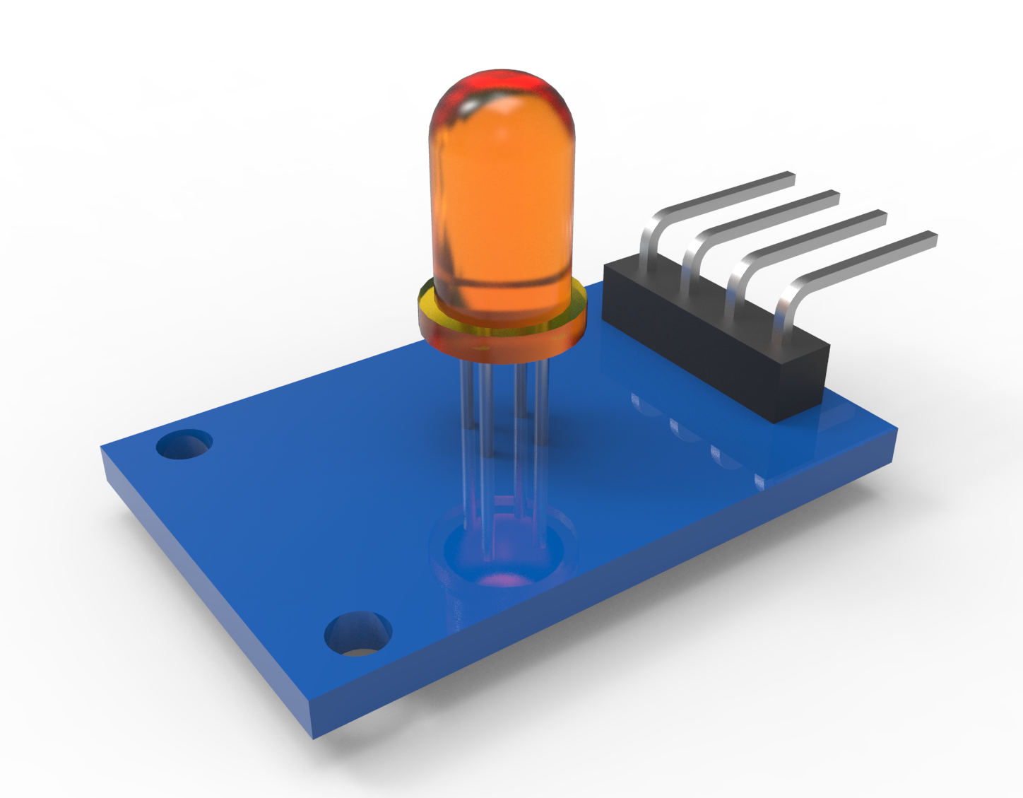
Flashing LED in Arduino, what could be simpler and more useless. In fact, the practical benefits of this simple function can be found.
It happens when programming a device that lacks the input / output ports of the microcontroller. Or, for economic reasons, and perhaps the lack of space in the case, I do not want to install the display, but I would like very much to signal the operation modes of the device. It is often enough to signal these modes by burning or flashing the LED. And if a lot of modes?
I was led to a thought by a car alarm system, in which I programmed the autorun mode. There, in order to set, for example, the 14th bit of a certain register, it was necessary to enter the programming mode of this register 14 times, press a certain key fob button, and then wait for 14 short beeps (or blinkers of turn signals). Then press the button in confirmation and hear a long beep. Brilliant! No displays and on-screen menus. True, at the same time, and terribly uncomfortable.
')
But if there are few internal modes, then using the number of LED blinks is quite functional.
Let's start with the simple.
Example of LED flashing for Arduino
This is the first program that is mastered when studying Arduino. In many controllers that I came across lately, this program is protected at the factory, apparently for those who have not mastered this.
The simplest example of LED blinking
void setup() { pinMode(13, OUTPUT); digitalWrite(13, LOW); } void loop() { digitalWrite(13,HIGH); delay(500); digitalWrite(13,LOW); delay(500); } 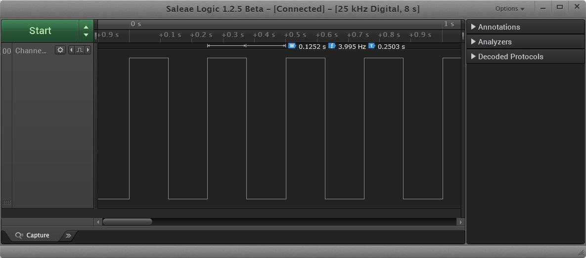
It would seem to set different intervals between the high and low levels of the port and would be necessary. But at the same time, the controller does nothing more (well, almost nothing, it still processes interrupts). He certainly can do something else, but not in the main loop ().
Therefore, we refuse delay () and go to events using millis ()
Using events using millis ()
LED flashing code using millis ()
void setup() { pinMode(13, OUTPUT); digitalWrite(13, LOW); } uint32_t ms, ms1 = 0; bool led_stat = true; void loop() { ms = millis(); // 500 if( ( ms - ms1 ) > 500 || ms < ms1 ){ ms1 = ms; // digitalWrite(13, led_stat); led_stat = !led_stat; } } Here you go. The goal is achieved. The LED flashes, and the processor time in the loop () loop is almost completely accessible to other functions. However, in such a code, the use of the required flashing modes is rather difficult to implement - several events with different intervals, many conditions for the required mode and the previous state. Too hard.
Processing the LED status matrix
Reduce the response time of the event to 1/8 seconds and in 1 byte we encode 8 bits of states displayed sequentially.
Flashing code of the LED with a bit matrix of states
// byte modes[] = { 0B00000000, // 0B11111111, // 0B00001111, // 0.5 0B00000001, // 0B00000101, // 0B00010101, // 0B01010101 // (4 ) }; uint32_t ms, ms1 = 0, ms2 = 0; uint8_t blink_loop = 0; uint8_t blink_mode = 0; uint8_t modes_count = 0; void setup() { pinMode(13, OUTPUT); digitalWrite(13, LOW); modes_count = 1; blink_mode = modes[modes_count]; } void loop() { ms = millis(); // 125 if( ( ms - ms1 ) > 125|| ms < ms1 ){ ms1 = ms; // if( blink_mode & 1<<(blink_loop&0x07) ) digitalWrite(13, HIGH); else digitalWrite(13, LOW); blink_loop++; } // // 5 if( ( ms - ms2 ) > 5000|| ms < ms2 ){ ms2 = ms; blink_mode = modes[modes_count++]; if( modes_count >= 7 )modes_count = 1; } } The first three modes of operation of the LED are simple. But the rest can already be used to demonstrate the microcontroller mode:
Short flash 1 time per second

Two flashes per second
Three flashes

And constant flashes four times a second.

In principle, it was possible to stop at this, since for most projects this would be enough. But if this is not enough and you will need to develop programming car alarm)))
What if 8 bits of LEDs are low?
Using 4 bytes to determine the state of the LED
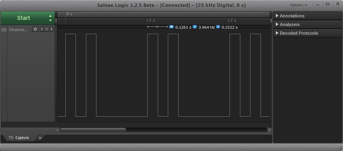
Morse code SOS signal code
byte bytes[] = {0B00010101,0B00110011,0B10100011,0B00000010}; uint32_t ms, ms1 = 0; uint8_t blink_loop = 0; void setup() { pinMode(13, OUTPUT); digitalWrite(13, LOW); } void loop() { ms = millis(); // 125 if( ( ms - ms1 ) > 125|| ms < ms1 ){ ms1 = ms; // (3 ) uint8_t n_shift = blink_loop&0x07; // (2 3 ) uint8_t b_count = (blink_loop>>3)&0x3; if( bytes[b_count] & 1<< n_shift )digitalWrite(13, HIGH); else digitalWrite(13, LOW); blink_loop++; } } We receive a cyclic SOS signal - three short, three long and again three short LED signals, repeated every 4 seconds

A lot of people criticized Arduino for the terrible programming style of microcontrollers without using interrupts.
Only hardcore. Only interrupts!
We take a 16-bit Timer 1. Set the interrupt on overflow for 125ms
Multimode LED flashing code using timer interrupts
uint8_t blink_loop = 0; uint8_t blink_mode = 0; uint8_t modes_count = 0; // uint16_t n = 63583; // ISR( TIMER1_OVF_vect ) { if( blink_mode & 1<<(blink_loop&0x07) ) digitalWrite(13, HIGH); else digitalWrite(13, LOW); blink_loop++; TCNT1 = n; // TCNT1 } void setup() { pinMode(13,OUTPUT); blink_mode = 0B00000000; // - TCCR1A = 0; // 1024 16 TCCR1B = 1<<CS22 | 0<<CS21 | 1<<CS20; // Timer1 TIMSK1 = 1<<TOIE1; // TCNT1 = n; sei(); // } } void loop() { blink_mode = 0B00001111; // 0.5 delay(5000); blink_mode = 0B00000001; // delay(5000); blink_mode = 0B00000101; // delay(5000); blink_mode = 0B00010101; // delay(5000); blink_mode = 0B01010101; // (4 ) delay(5000); } Details on programming timer can be read here . At the same time, delay () for 5 seconds in Loop () does not interfere at all with the control of our LED.
The disadvantage of this method is that some functions and libraries that use timer 1 will not work. For example, PWM.
If it is difficult to program timer registers, it is interesting to use a timer interrupt -
Timer interrupt with a “human face”
Kind people wrote a program interface to the timer in the form of a library TimerOne
Multimode LED flashing code using TimerOne
#include "TimerOne.h" uint8_t blink_loop = 0; uint8_t blink_mode = 0; uint8_t modes_count = 0; // Callback void timerIsr() { if( blink_mode & 1<<(blink_loop&0x07) ) digitalWrite(13, HIGH); else digitalWrite(13, LOW); blink_loop++; } void setup() { pinMode(13,OUTPUT); blink_mode = 0B00000000; Timer1.initialize(125000); Timer1.attachInterrupt( timerIsr ); } void loop() { blink_mode = 0B00001111; // 0.5 delay(5000); blink_mode = 0B00000001; // delay(5000); blink_mode = 0B00000101; // delay(5000); blink_mode = 0B00010101; // delay(5000); blink_mode = 0B01010101; // (4 ) delay(5000); } TimerOne Time Library can be downloaded here.
Well, and finally, the code is for those who, like me, “nibble” the programming of the ESP8266 WiFi modules in the Arduino IDE.
Timer Interrupt in ESP8266
There are other good people right in the core of ESP for Arduino built Ticker library
Multi-Timer LED Timer Flashing Code in ESP8266
#include <Ticker.h> uint8_t blink_loop = 0; uint8_t blink_mode = 0; uint8_t modes_count = 0; Ticker blinker; void timerIsr() { if( blink_mode & 1<<(blink_loop&0x07) ) digitalWrite(13, HIGH); else digitalWrite(13, LOW); blink_loop++; } void setup() { pinMode(13,OUTPUT); blink_mode = 0B00000000; blinker.attach(0.125, timerIsr); } void loop() { blink_mode = 0B00001111; // 0.5 delay(5000); blink_mode = 0B00000001; // delay(5000); blink_mode = 0B00000101; // delay(5000); blink_mode = 0B00010101; // delay(5000); blink_mode = 0B01010101; // (4 ) delay(5000); } Use ESP interrupts with caution, since very often this triggers the malicious WDT watchdog timer, which believes that too little time is allotted for processing embedded WiFi functions.
I hope this article will be a little useful for all lovers of flashing LEDs in Arduino and not only them.
Read about all my experiments with microcontrollers and smart home in my blog.
Source: https://habr.com/ru/post/357904/
All Articles