Dual axis solar tracker on Arduino
For a start, it's probably worth telling what is meant in this article by the solar tracker. In short, the device is a movable stand for the solar panel, which is necessary so that in our temperate latitudes the panel collects a sufficient amount of light, changing its position after the sun.
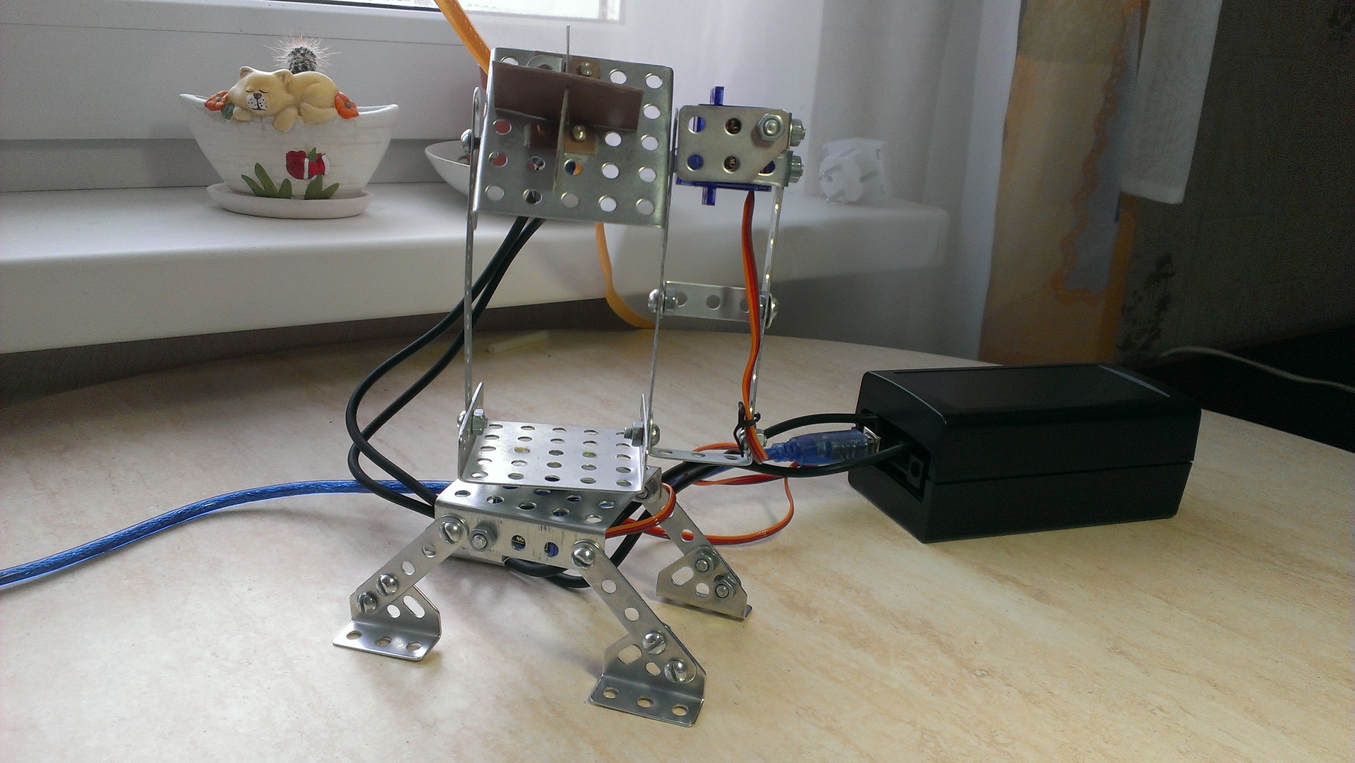
In this case, the prototype of the solar tracker was going on the basis of Arduino. To rotate the platform in the horizontal and vertical axis, servo drives are used, the angle of rotation of which depends on the power of the light incident on the photoresistors. As the body is used by everyone's favorite Soviet metal constructor.
It is useful to mention that all this was done as a course project, so I did not deal with the acquisition and fastening of the solar panel itself and the battery itself, since their presence is not related to the work of the tracker. In justification, I can say that the possibilities of the Soviet metal constructor are immense, so that screwing a small solar panel to charge the phone to it will not be difficult if such a desire arises.
So, what was used in the assembly:
')
Mega was used solely because of its presence in the closet at the time of the approval of the project's theme, given the purchase of all the elements from scratch, in this case Uno is quite enough for itself, but it will certainly be cheaper.
The speaker who was suddenly on the list was needed to heighten the effect of high-tech. The fact is that the servos can be rotated only 180 degrees, and more and we do not need, given that we are watching the sun. But when testing the project, when the sun in two minutes of the demonstration is not particularly followed, it turned out that it would be nice to signal at what point you should stop swinging the flashlight, because the servo drive reached the dead zone. For this, the aforementioned call was added.
So, let's start collecting the tracker. To begin, let us divide the upcoming work into conditional four stages: assembling a stand for solar panels and fixing servo drives, fixing to the assembled design of photosensitive elements, soldering and writing code for the Arduino.
Through intensive search, a couple of examples of the construction of similar devices were found. Two received the most attention:
Assembling from a metal constructor was associated with certain difficulties: the drill had to fit the holes for connecting servos and securely glue them to the platforms in two planes. What happened is shown in the video below.
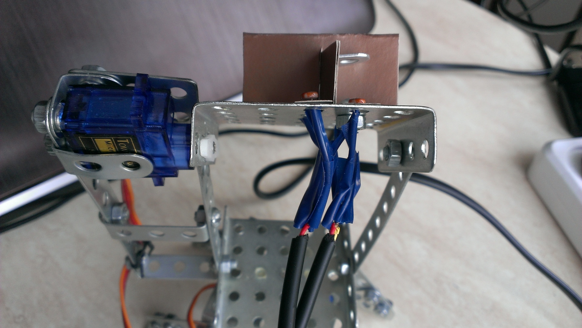
The main task of mounting the photoresistors was not even to connect them, but to ensure the separation of light for each of the four elements. It is clear that it was impossible to leave them without any partitions, since then the values obtained from the photoresistors would be approximately the same and the rotation would not work. Here, unfortunately, the possibilities of the metal constructor were let down, mainly due to the presence of holes in all the details. It did not work out to find a suitable metal part, so my solar tracker acquired an innovative cardboard partition. Despite the rather poor appearance, it fulfills its purpose perfectly.
The photoresistors are securely attached to the case, the only thing worth working with is the accuracy of their location on the platform: now they are looking upward not perpendicularly, which can upset the perfectionists and slightly spoil the turning accuracy.
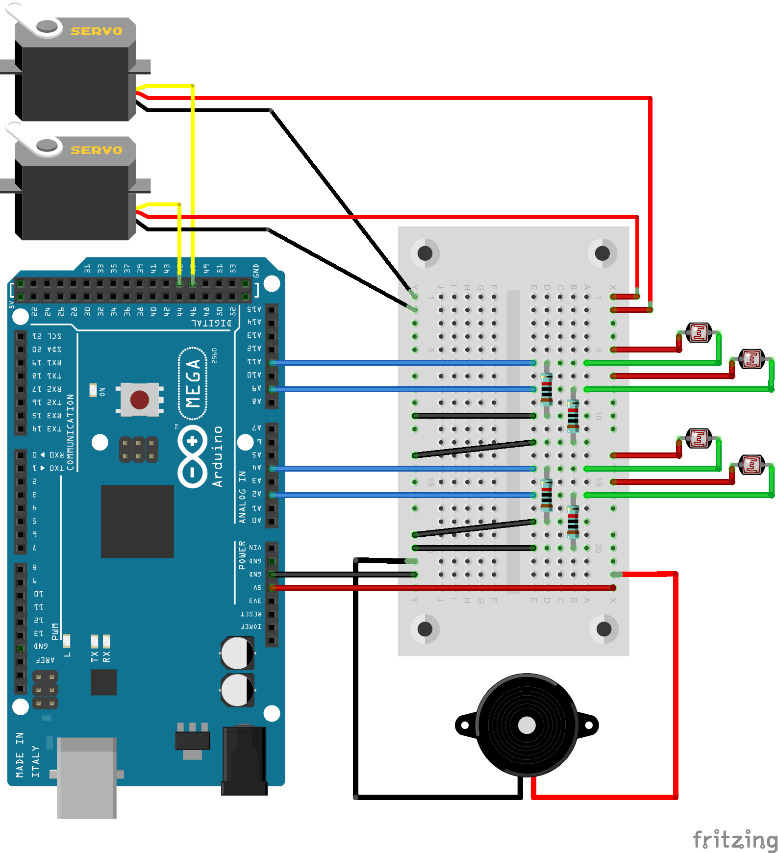
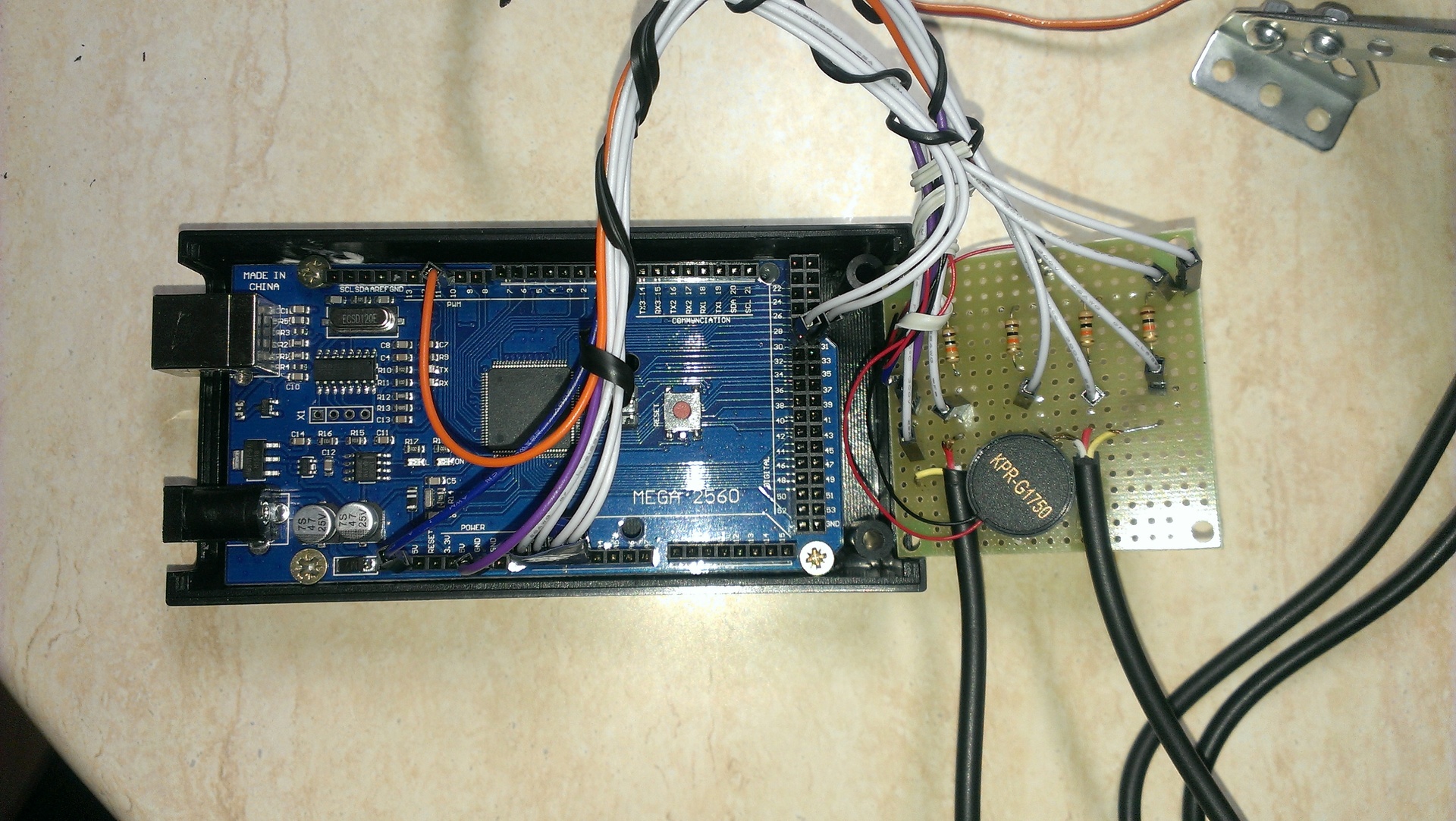
It is a little circuit engineering: connection of photosensitive elements is carried out under the scheme of a voltage divider for what the output resistors specified in the list of elements were required. All photoresistors are soldered to a common contact connected to the five-voltage output of the Arduino. For convenience and aesthetics, the photoresistors' legs are soldered to the contacts of two three-core insulated wires (one contact remained unused and hidden). All circuit details can be seen in the diagram below.
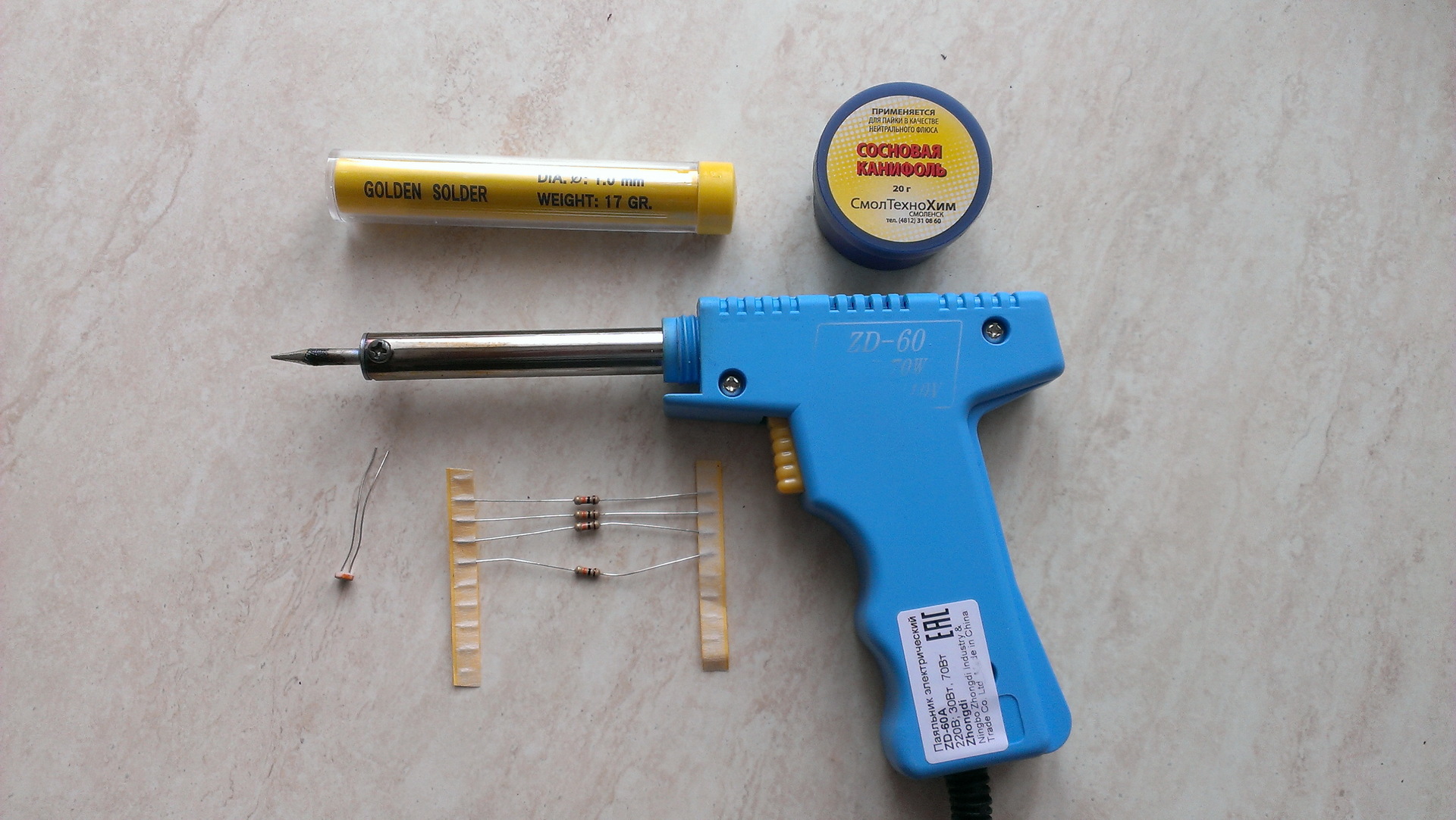
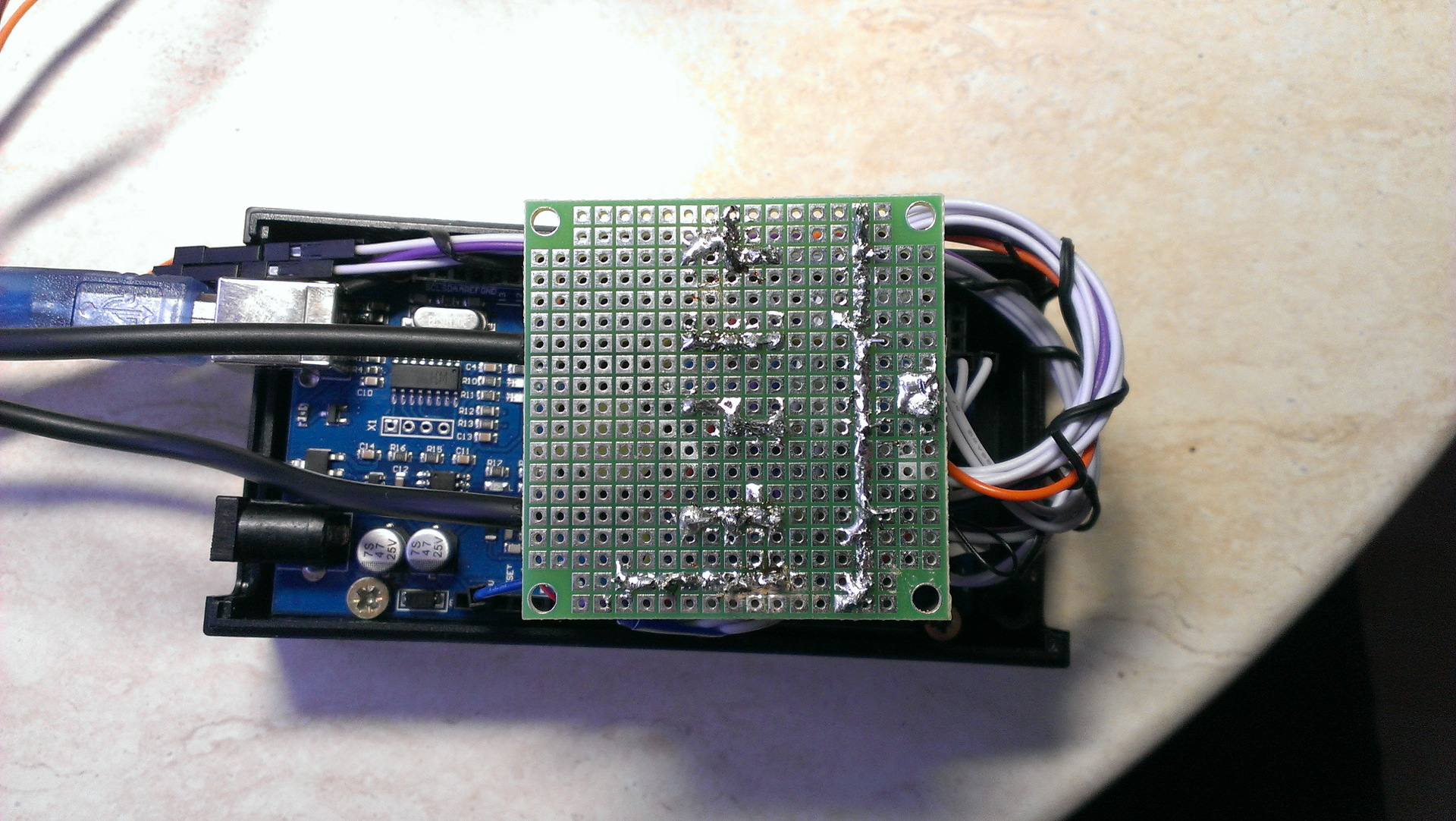
Describing something in detail here does not make much sense, so I simply attach a photo of the materials used and the resulting design board.
The general algorithm of work consists in processing data from photoresistors using an ADC. We have 4 elements, that is, 4 readings, we find the average reading on the left side ((upper left + lower left) / 2), similarly on the right, upper and lower sides. If the difference in absolute value between the left and right side is greater than the threshold, then we make a turn in the direction with a large average value. Similarly for the top and bottom. Special buns in the code: you can manually set the response sensitivity and the maximum and minimum angle in two planes. A listing of the working code is below.
In this case, the prototype of the solar tracker was going on the basis of Arduino. To rotate the platform in the horizontal and vertical axis, servo drives are used, the angle of rotation of which depends on the power of the light incident on the photoresistors. As the body is used by everyone's favorite Soviet metal constructor.
It is useful to mention that all this was done as a course project, so I did not deal with the acquisition and fastening of the solar panel itself and the battery itself, since their presence is not related to the work of the tracker. In justification, I can say that the possibilities of the Soviet metal constructor are immense, so that screwing a small solar panel to charge the phone to it will not be difficult if such a desire arises.
So, what was used in the assembly:
')
- Arduino MEGA 2560 R3
- Servo Tower SG90 - 2x
- Photoresistor MLG4416 (90mW; 5-10kOhm / 1.0MOhm) - 4x
- Call piezoelectric KPR-G1750
- Metal constructor
- Output resistor 10 kOhm; 0.25W; 5% - 4x
- Printed breadboard, case, cords for connection
Mega was used solely because of its presence in the closet at the time of the approval of the project's theme, given the purchase of all the elements from scratch, in this case Uno is quite enough for itself, but it will certainly be cheaper.
The speaker who was suddenly on the list was needed to heighten the effect of high-tech. The fact is that the servos can be rotated only 180 degrees, and more and we do not need, given that we are watching the sun. But when testing the project, when the sun in two minutes of the demonstration is not particularly followed, it turned out that it would be nice to signal at what point you should stop swinging the flashlight, because the servo drive reached the dead zone. For this, the aforementioned call was added.
So, let's start collecting the tracker. To begin, let us divide the upcoming work into conditional four stages: assembling a stand for solar panels and fixing servo drives, fixing to the assembled design of photosensitive elements, soldering and writing code for the Arduino.
The first figure: design
Through intensive search, a couple of examples of the construction of similar devices were found. Two received the most attention:
- www.youtube.com/watch?v=SvKp3V9NHZY - the winner in the nomination "Material Feed" lost in reliability and practicality of the device: the design is a connection of two servo drives directly.
- www.instructables.com/id/Simple-Dual-Axis-Solar-Tracker - in fact, this is where the basic idea of my design was taken, with the exception of the material and the general appearance of the rotary body.
Assembling from a metal constructor was associated with certain difficulties: the drill had to fit the holes for connecting servos and securely glue them to the platforms in two planes. What happened is shown in the video below.
Figure Two: circuit design
The main task of mounting the photoresistors was not even to connect them, but to ensure the separation of light for each of the four elements. It is clear that it was impossible to leave them without any partitions, since then the values obtained from the photoresistors would be approximately the same and the rotation would not work. Here, unfortunately, the possibilities of the metal constructor were let down, mainly due to the presence of holes in all the details. It did not work out to find a suitable metal part, so my solar tracker acquired an innovative cardboard partition. Despite the rather poor appearance, it fulfills its purpose perfectly.
The photoresistors are securely attached to the case, the only thing worth working with is the accuracy of their location on the platform: now they are looking upward not perpendicularly, which can upset the perfectionists and slightly spoil the turning accuracy.
It is a little circuit engineering: connection of photosensitive elements is carried out under the scheme of a voltage divider for what the output resistors specified in the list of elements were required. All photoresistors are soldered to a common contact connected to the five-voltage output of the Arduino. For convenience and aesthetics, the photoresistors' legs are soldered to the contacts of two three-core insulated wires (one contact remained unused and hidden). All circuit details can be seen in the diagram below.
Figure Three: Soldering
Describing something in detail here does not make much sense, so I simply attach a photo of the materials used and the resulting design board.
The fourth figure: with the new code!
The general algorithm of work consists in processing data from photoresistors using an ADC. We have 4 elements, that is, 4 readings, we find the average reading on the left side ((upper left + lower left) / 2), similarly on the right, upper and lower sides. If the difference in absolute value between the left and right side is greater than the threshold, then we make a turn in the direction with a large average value. Similarly for the top and bottom. Special buns in the code: you can manually set the response sensitivity and the maximum and minimum angle in two planes. A listing of the working code is below.
Code
#include <Servo.h> Servo horizontal; int servoh = 90; int servohLimitHigh = 180; int servohLimitLow = 0; Servo vertical; int servov = 45; int servovLimitHigh = 180; int servovLimitLow = 0; int ldrlt = A2; //LDR top left - BOTTOM LEFT int ldrrt = A3; //LDR top rigt - BOTTOM RIGHT int ldrld = A1; //LDR down left - TOP LEFT int ldrrd = A0; //ldr down rigt - TOP RIGHT int buzz_pin = 10; int buzz_tone = 20; int tol = 50; void setup() { Serial.begin(9600); pinMode(buzz_pin, OUTPUT); horizontal.attach(31); vertical.attach(30); horizontal.write(servoh); vertical.write(servov); } void loop() { int lt = analogRead(ldrlt); // top left int rt = analogRead(ldrrt); // top right int ld = analogRead(ldrld); // down left int rd = analogRead(ldrrd); // down rigt int avt = (lt + rt) / 2; // average value top int avd = (ld + rd) / 2; // average value down int avl = (lt + ld) / 2; // average value left int avr = (rt + rd) / 2; // average value right int dvert = abs(avt - avd); // check the diffirence of up and down int dhoriz = abs(avl - avr);// check the diffirence of left and right Serial.print("avt: "); Serial.print(avt); Serial.print(" "); Serial.print("avd: "); Serial.print(avd); Serial.print(" "); Serial.print("avl: "); Serial.print(avl); Serial.print(" "); Serial.print("avr: "); Serial.println(avr); Serial.print("h: "); Serial.print(servoh); Serial.print(" "); Serial.print("v: "); Serial.print(servov); Serial.print(" "); if (dhoriz > tol) { if (avl > avr) { if (servoh - 1 >= servohLimitLow) servoh--; else beep(150); } else if (avl < avr) { if (servoh + 1 <= servohLimitHigh) servoh++; else beep(150); } horizontal.write(servoh); } if (dvert > tol) { if (avt > avd) { if (servov + 1 <= servovLimitHigh) servov++; else beep(100); } else if (avt < avd) { if (servov - 1 >= servovLimitLow) servov--; else beep(100); } vertical.write(servov); } } void beep(unsigned char delayms){ analogWrite(buzz_pin, buzz_tone); delay(delayms); analogWrite(buzz_pin, 0); delay(delayms); } Work result
Conclusion - what would I change now in the project
- Improvement of the operation algorithm: dependence of the degree of rotation on the difference of values obtained from photoresistors, that is, rotation by several degrees at once.
- Ideal perpendicular mounting of photoresistors to the platform.
- Bluetooth for the lack of wires - of course, the idea is not bad, but it will require significant improvements in the design and the acquisition of the second arduin.
- The use of servo drives with metal gears (reliability and more confident turns will not hurt, especially if you add a solar panel to the structure and use it for its intended purpose).
Source: https://habr.com/ru/post/357900/
All Articles