DMX-512 Channel Level Transmission Visualization
By the nature of the activity, I often have to develop all kinds of control systems for lighting effects. In cases where the functionality of the controllers on the market is redundant for the customer, it is necessary to reinvent a simple controller almost on the knee for a specific object. The challenge is unique each time. Starting from a single channel, pulsing like a heart to controlling a “garland” of decoders working using the DMX-512 protocol or on WS28xx microchips:
Simplest DMX Decoder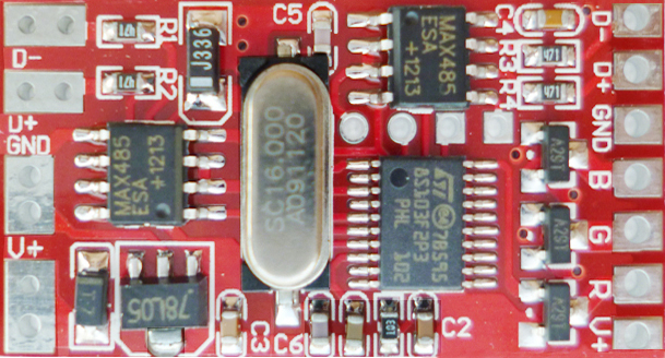
')
Cost a penny from the Chinese . I really love these decoders. With their help, you can easily scale the system from three to 512 channels.
')
Cost a penny from the Chinese . I really love these decoders. With their help, you can easily scale the system from three to 512 channels.
For me, the most convenient option is the well-known Arduino board. It is very convenient to keep a dozen or two clones of the Arduino Pro Mini in the box and use them in similar projects as needed. I love it for the fact that at its base you can quickly assemble a fairly compact device and there are these clones in China, about the same as the naked Atmaga328.
And when developing effects for the next controller for 16 channels, working under the DMX-512 protocol, I was finally tortured to lay out a net of wires on a twist on the table in order to debug the effects once and sort it all out again. I was puzzled by the search for devices for analyzing DMX packets, but it turned out that these are very rare and rather expensive instruments. This prompted me to create my own DMX tester.
Initially, I decided that I needed a device that would be able to display channel levels in real time and that would be enough, but after thinking a bit, I determined the following task list:
- Display channel levels in real time in relative units;
- Displays the total number of channels to which the controller provides data;
- Displays the level of one selected channel in absolute units (0-255);
Display channel levels, it was taken in the form of bars, i.e., if you use a 16x2 character LCD display, then you can already watch 16 channels at a time in one line. Since channels can be up to 512, it would be nice to be able to scroll the displayed range of channels.
Well, once the task is set, let's move on to the hardware. Basically, as I already wrote, I have a clone of the Arduino Pro Mini:
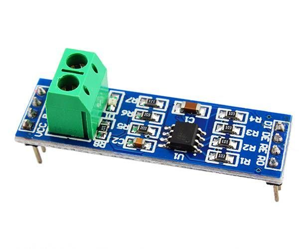
We will receive data through the simplest TTL to RS-485 adapter, based on the MAX485.
" 
Well, we will display information on a 16x2 LCD display (I’ll make a reservation right away that at the time of development I have already ordered a similar 40x2 display, which will fall into place in the final device). I will manage all this through the keyboard, described here by a friend of kumbr_87 .
No sooner said than done.
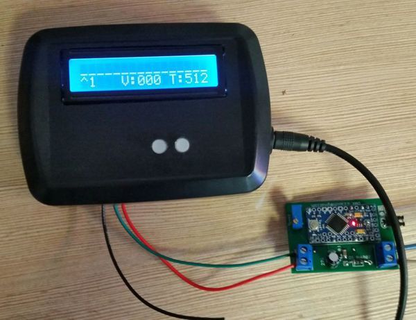
On prototype assembled prototype
Wrote a sketch
#include <Wire.h> #include <LiquidCrystal.h> #include <Conceptinetics.h> #define DMX_SLAVE_CHANNELS 512 #define LCD_W 16 // ( ) LiquidCrystal lcd(12, 11, 5, 4, 3, 2); DMX_Slave dmx_slave ( DMX_SLAVE_CHANNELS ); unsigned long lastFrameReceivedTime = 0; // unsigned long lastFrameTranceivedTime = 0; // byte qa[8] = { B00000, B00000, B00000, B00000, B00000, B00000, B00000, B11111 }; byte ws[8] = { B00000, B00000, B00000, B00000, B00000, B00000, B11111, B11111 }; byte ed[8] = { B00000, B00000, B00000, B00000, B00000, B11111, B11111, B11111 }; byte rf[8] = { B00000, B00000, B00000, B00000, B11111, B11111, B11111, B11111 }; byte tg[8] = { B00000, B00000, B00000, B11111, B11111, B11111, B11111, B11111 }; byte yh[8] = { B00000, B00000, B11111, B11111, B11111, B11111, B11111, B11111 }; byte uj[8] = { B00000, B11111, B11111, B11111, B11111, B11111, B11111, B11111 }; byte ik[8] = { B11111, B11111, B11111, B11111, B11111, B11111, B11111, B11111 }; byte outAr [LCD_W]; // , unsigned short chRx; // #define KEY_BUTTON_1_PIN A2 // unsigned int KeyButton1Value=0; // unsigned long KeyButton1TimePress=0; // unsigned long KeyButton1Latency=100; // unsigned int KeyButton1WasChecked=0; // unsigned long KeyButton1RepeatLatency=1500; // unsigned long KeyButton1RepeatTimePress=0; // unsigned long KeyButton1TimeFromPress=0; // unsigned long KeyBoardTime1=0; // unsigned long KeyBoardTime2=0; // unsigned long KeyBoardTimeInterval=25; // byte start = 0; // +1 , void setup() { lcd.begin(LCD_W, 2); dmx_slave.enable (); dmx_slave.setStartAddress (1); dmx_slave.onReceiveComplete ( OnFrameReceiveComplete ); lcd.createChar(0,qa); lcd.createChar(1,ws); lcd.createChar(2,ed); lcd.createChar(3,rf); lcd.createChar(4,tg); lcd.createChar(5,yh); lcd.createChar(6,uj); lcd.createChar(7,ik); pinMode (KEY_BUTTON_1_PIN, INPUT); pinMode (10, OUTPUT); pinMode (9, OUTPUT); digitalWrite(9, LOW); } void loop() { // KeyBoardTime2=millis(); if ((KeyBoardTime2-KeyBoardTime1)>KeyBoardTimeInterval) { KeyBoardTime1=KeyBoardTime2; KeyBoardCalculate(); } if (lastFrameReceivedTime > lastFrameTranceivedTime){ // printLevel (outAr); // lastFrameTranceivedTime = millis(); } else if ((lastFrameReceivedTime==0 && lastFrameTranceivedTime ==0)||(KeyBoardTime2-lastFrameReceivedTime>2000)) { lcd.clear(); delay (500); lcd.setCursor(0, 0); lcd.print("NO SIGNAL"); delay (500); } } void OnFrameReceiveComplete (unsigned short channelsReceived) // , { chRx = channelsReceived; // , for (byte i=0; i<LCD_W; i++){ // outAr[i]=dmx_slave.getChannelValue (i+start+1); } lastFrameReceivedTime = millis(); } void printLevel(byte lv[LCD_W]) // { byte dispLv[LCD_W]; for (byte i=0; i<LCD_W; i++){ switch (lv[i]/32) { //// case 0: dispLv[i]=0; break; case 1: dispLv[i]=1; break; case 2: dispLv[i]=2; break; case 3: dispLv[i]=3; break; case 4: dispLv[i]=4; break; case 5: dispLv[i]=5; break; case 6: dispLv[i]=6; break; case 7: dispLv[i]=7; break; } } lcd.setCursor(0, 0); for (byte i=0; i<LCD_W; i++){ // lcd.write(dispLv[i]); // } // lcd.setCursor(0, 1); lcd.print("^"); // if ((start+1)<10) { // lcd.print((start+1)); // lcd.print(" "); // } else if ((start+1)<100 && (start+1)>9) { // lcd.print((start+1)); // lcd.print(" "); // } else lcd.print((start+1)); // lcd.setCursor(5, 1); lcd.print("V:"); // if (lv[0]<10) { // lcd.print("00"); // lcd.print(lv[0]); // } else if (lv[0]<100 && lv[0]>9) { // lcd.print("0"); // lcd.print(lv[0]); // } else lcd.print(lv[0]); // lcd.setCursor(11, 1); lcd.print("T:"); // lcd.print(chRx); // } void ButtonPress() // , { if ((KeyButton1Value>200) and (KeyButton1Value<500)) { if((start) < (chRx-LCD_W) && chRx>LCD_W) start++; // } if ((KeyButton1Value>500) and (KeyButton1Value<1000)) { if(start > 0) start--; // } } void KeyBoardCalculate() { // KeyButton1Value=analogRead(KEY_BUTTON_1_PIN); // if ((KeyButton1Value<=50) or (KeyButton1Value>=1000)) { // KeyButton1TimePress=millis(); KeyButton1WasChecked=0; KeyButton1RepeatTimePress=0; } KeyButton1TimeFromPress=millis()-KeyButton1TimePress; // if ((KeyButton1Value>50) and (KeyButton1Value<1000)) { // if ( ((KeyButton1TimeFromPress)>KeyButton1Latency) and (KeyButton1WasChecked==0)) { KeyButton1Value=analogRead(KEY_BUTTON_1_PIN); ButtonPress(); KeyButton1WasChecked=1; KeyButton1RepeatTimePress=0; } // if ( ((KeyButton1TimeFromPress)>(KeyButton1RepeatLatency+KeyButton1RepeatTimePress)) and (KeyButton1WasChecked==1)) { KeyButton1Value=analogRead(KEY_BUTTON_1_PIN); ButtonPress(); KeyButton1RepeatTimePress=KeyButton1RepeatTimePress+100; } } } And oddly enough, it all worked! The columns "jumped" in accordance with the received data. By this time, the 40x2 display had just arrived. I connected it, remade the sketch under the display for 40 characters, filled it, and then the inexplicable happened.
At the moment when the microcontroller starts up, in the first displayed frame, all the information is correct. When displaying subsequent frames, the arduino eats several channels somewhere. Those. if the controller outputs data to 60 channels, then at the moment arduino is turned on or rebooted, the total number of channels is 60 and the first channel on the display is indeed the first. But immediately after the frame change, the number of frames is 57, and the first is displayed, in reality, the fifth. I also tried to drive the signal into 30 channels - the same thing, only at first everything is correct, and then it shows the total number of channels 29, and in the place of the first one it shows that it is not clear at all.
Everything else works without problems - scrolling scrolls. Can someone see with a fresh eye ... Yes, by the way, if you give a signal for <17 channels, then everything is displayed correctly.
I thought about this problem for a week, but did not find a solution. As a result, I decided to stop at the initial display of 16 characters. I washed down the case, assembled it and everything works to this day.
Source: https://habr.com/ru/post/357888/
All Articles