Laser link between two Arduino Morse code
Why a laser beam, and not radio? For fun. In order to ensure secrecy, radio broadcasts intercept everyone who feels like it, and they do not realize the interception of flashes of light, moreover, you need to stand in the direction of transmission of the beam. It can be used where radio communication is not possible due to strong interference.
For the experiment, we need:
The transmitter is connected as the simplest scheme in Arduin (Blink), you can blink the Morse code and the usual LED, but for a short distance, you will need to use a laser to transmit to meter distances. The laser can be taken either from a laser pointer or to buy in the store a special module for Arduino with 3 contacts:

Arduino laser connection scheme:
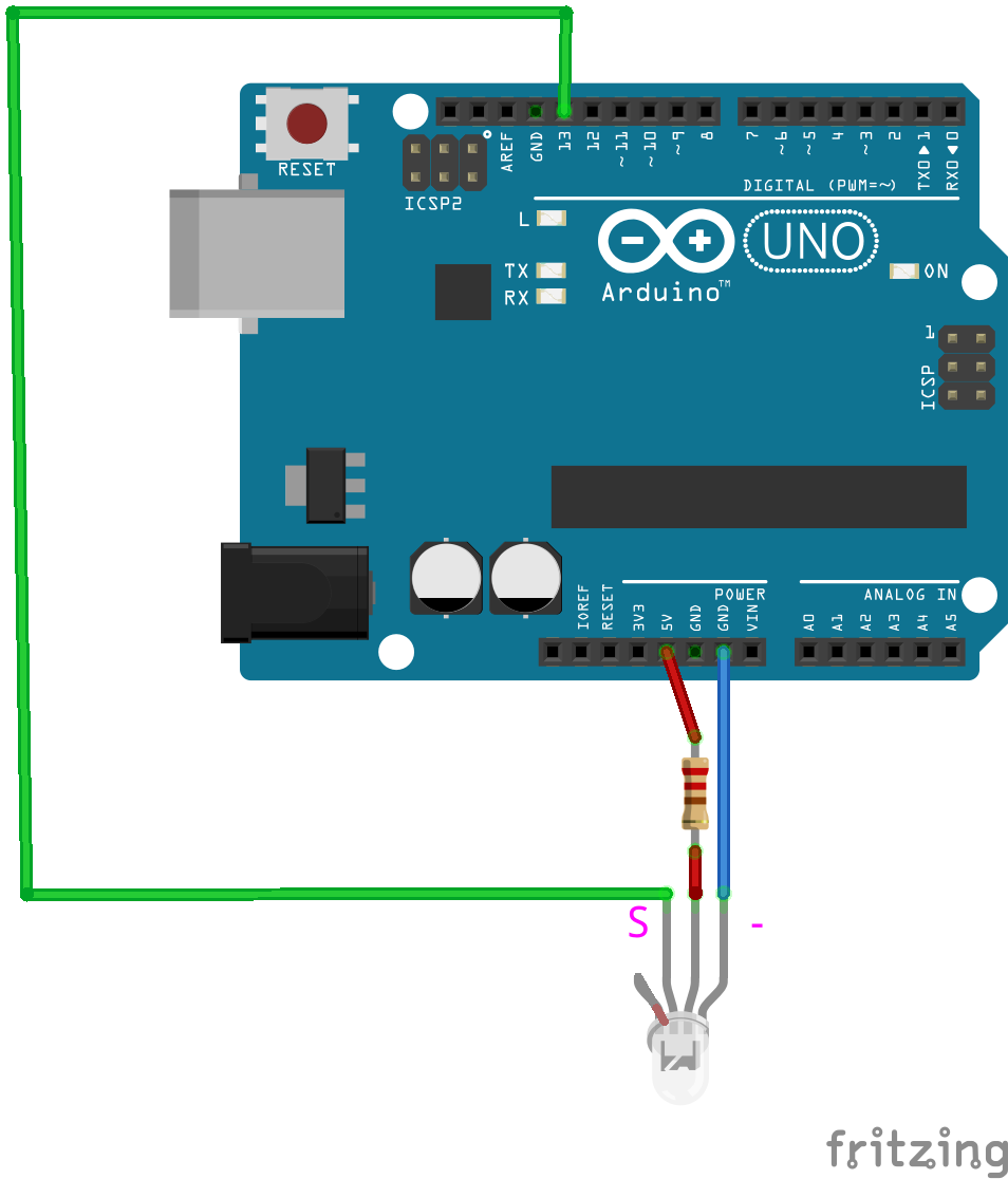
Since the KY-008 part was not found in the fritzing on the scheme, we had to use the RGB LED, signing the legs S and “-“, S pin is connected to the 13th leg, minus to GND (ground).
To transmit data, we use the Morse code - a way of representing the letters of the alphabet by a sequence of long (“dash”) and short (“dot”) signals. Of course, when transmitting by Morse code, there is no error correction, but for a test transmission, you can do without it. Since we still know the sequence of transmitted characters.
In the sketch code, we indicate on which contact the Morse code will be fed, 13 foot (as for most blink.ino blinking sketches by the LED), the second parameter is responsible for the transfer speed (24 words per minute), 3 parameter 1 for the beep sound signal and 0 for PTT ( pin switching to HIGH and LOW). If you look at the Morse.cpp code, you will see that for the third parameter 1 - beep is used as an analog output to write to the pin:
analogWrite (_pin, 128);
delay (_dashlen);
analogWrite (_pin, 0);
delay (_dotlen);
and for 0, it is used as a digital output.
digitalWrite (_pin, HIGH);
delay (_dashlen);
digitalWrite (_pin, LOW);
delay (_dotlen);
In our case, use the code: Morse morse (13, 24, 0);
For the sketch is necessary library morze.zip author Erik Linder. Sketch transmitter is simple:
Fill the sketch, the system is ready for data transfer.
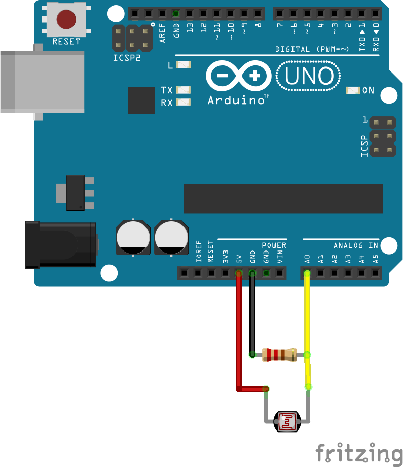
We assemble the receiver circuit, nothing complicated, the photoresistor is one leg with 5V second leg analog port A0, 10 kΩ resistor - one leg GND (“ground”), second leg A0:
The received data is output to the COM port, which is of course great, but not visual and requires the presence of a computer. Therefore, we connect a 2 line screen with an I2C connection:
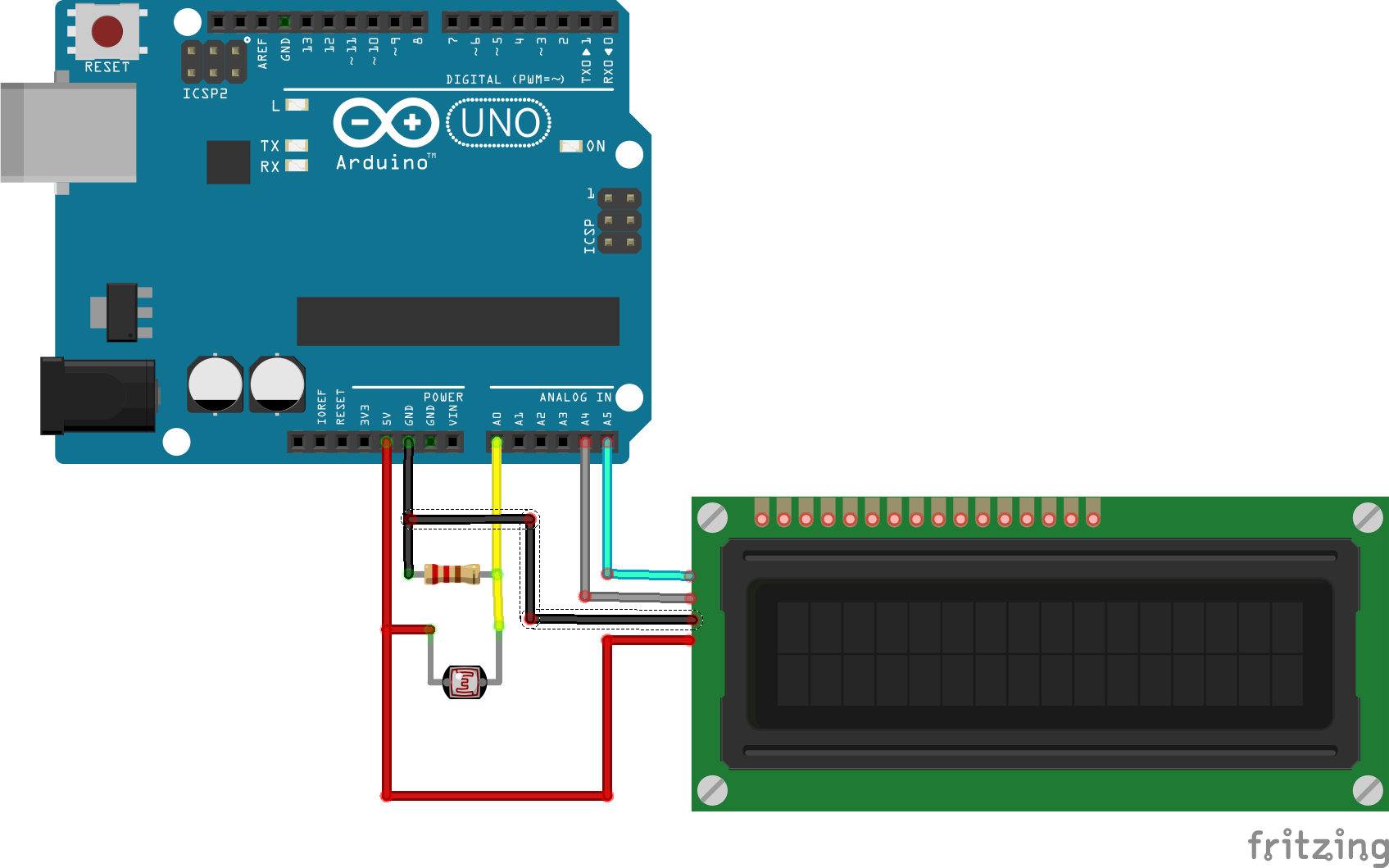
For the SDA screen, connect the leg of the arduino UNO A5, SCL - A4, screen VCC to 5V, GND to GND:
Add in the receiver.ino receiver sketch the lines responsible for the output on the 2 line LCD screen. You can now go to the field with a compact receiver and read the message directly from the LCD screen.
This transmission method worked successfully for me as in the room in the evening at a distance of 0.5–3 meters, and in the evening on the street at a distance of 7–14 m. Large distances have not yet been tested. Transmission during the day will require a light-proof tube so that sunlight and daylight do not fall on the photocell, but only the light from the laser or you need to play around with the LEVEL_LDR parameter responsible for light sensitivity in the receiver's sketch.
For the experiment, we need:
- 2 Arduino;
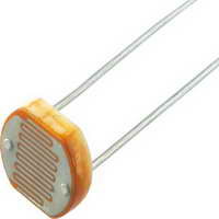
- 1 Photoresistor (or LDR) VT90N - a component that changes the resistance depending on the amount of light incident on it. In total darkness, it has a maximum resistance of hundreds of kilo-ohm, and as illumination grows, the resistance decreases to dozens of kilo-ohm:
- 1 laser module KY-008:
')
- 2 resistances: 220 Ohms for the transmitter, 10 kOhms for the receiver.
Transmitter
The transmitter is connected as the simplest scheme in Arduin (Blink), you can blink the Morse code and the usual LED, but for a short distance, you will need to use a laser to transmit to meter distances. The laser can be taken either from a laser pointer or to buy in the store a special module for Arduino with 3 contacts:
Arduino laser connection scheme:
Since the KY-008 part was not found in the fritzing on the scheme, we had to use the RGB LED, signing the legs S and “-“, S pin is connected to the 13th leg, minus to GND (ground).
To transmit data, we use the Morse code - a way of representing the letters of the alphabet by a sequence of long (“dash”) and short (“dot”) signals. Of course, when transmitting by Morse code, there is no error correction, but for a test transmission, you can do without it. Since we still know the sequence of transmitted characters.
In the sketch code, we indicate on which contact the Morse code will be fed, 13 foot (as for most blink.ino blinking sketches by the LED), the second parameter is responsible for the transfer speed (24 words per minute), 3 parameter 1 for the beep sound signal and 0 for PTT ( pin switching to HIGH and LOW). If you look at the Morse.cpp code, you will see that for the third parameter 1 - beep is used as an analog output to write to the pin:
analogWrite (_pin, 128);
delay (_dashlen);
analogWrite (_pin, 0);
delay (_dotlen);
and for 0, it is used as a digital output.
digitalWrite (_pin, HIGH);
delay (_dashlen);
digitalWrite (_pin, LOW);
delay (_dotlen);
In our case, use the code: Morse morse (13, 24, 0);
For the sketch is necessary library morze.zip author Erik Linder. Sketch transmitter is simple:
sketch transmitter
// Author Erik Linder // Released 2011 under GNU GPLv3 // // Usage: morse( <pin number>, <speed WPM>, <1=beep, 0=PTT> ) // sendmsg( "<text-to-send>" ) // #include <Morse.h> // Use pin 13 (built-in LED of Arduino 2009) Morse morse(13, 24, 1); void setup() { } void loop() { morse.sendmsg("HELLO WORLD!"); delay (2000); } Fill the sketch, the system is ready for data transfer.
Receiver
We assemble the receiver circuit, nothing complicated, the photoresistor is one leg with 5V second leg analog port A0, 10 kΩ resistor - one leg GND (“ground”), second leg A0:
receiver sketch
int LDR_Pin = A0; //analog pin 0 int led = 13; // 10k between GND and A0 // LDR between 5V and A0 #define MORSE_EMPTY 0 // . #define MORSE_DOT '*' #define MORSE_DOT2 '+' #define MORSE_TIRE '-' // ( ) #define MAX_MORSE_SYMBOL_LENGTH 8 char* morseSymbol[MAX_MORSE_SYMBOL_LENGTH]; unsigned int morseSymbolLen; char* newMorseSignal; // - . // . N- n- . char* code[] = { "*-","-***","*--","--*","-**","*","***-","--**","**","*---", "-*-","*-**","--","-*","---","*--*","*-*","***","-","**-", "**-*","****","-*-*","---*","----","--*-","-*--","-**-","**-**","**--", "*-*-", "*----","**---","***--","****-","*****","-****","--***","---**","----*","-----", "......","*-*-*-","---***","-*-*-","-*--*-","*----*","*-**-*","-****-","-**-*","**--**","--**--", "-***-","********","*--*-*","**-*-", "" }; // . char* layoutCyrillic[] = { "","","","","","","","","","", "","","","","","","","","","", "","","","","","","","","","", "", "1","2","3","4","5","6","7","8","9","0", ".",",",":",";","(","\'","\"","-","/","?","!", " *DELIMITER* "," *ERR* ","@"," *END* ", "" }; // . char* layoutLatin[] = { "a","b","w","g","d","e","v","z","i","j", "k","l","m","n","o","p","r","s","t","u", "f","h","c","ö","ch","q","y","x","é","ü", "ä", "1","2","3","4","5","6","7","8","9","0", ".",",",":",";","(","\'","\"","-","/","?","!", " *DELIMITER* "," *ERR* ","@"," *END* ", "" }; char** currentLayout; char** newLayout; void setup(){ Serial.begin(9600); pinMode(led, OUTPUT); morseSymbolLen = 0; newMorseSignal = MORSE_EMPTY; } int counter_high = 0; int counter_low = 0; int i; void loop(){ int LDRReading = analogRead(LDR_Pin); if (LDRReading >= 800){ counter_high++ ; if ( counter_low > 0 ){ // Serial.print("Low\t"); // Serial.print(counter_low); // Serial.print("\n"); } if ( counter_low > 1200) { // for (i = 0; i< morseSymbolLen; i++) { // Serial.print( currentLayout[i]); // } sendMorseSymbol(); morseSymbolLen=0; Serial.println(); //currentLayout[0]=" "; //currentLayout[1]=" "; //currentLayout[2]=" "; //currentLayout[3]=" "; //currentLayout[4]=" "; //currentLayout[5]=" "; //currentLayout[6]=" "; //currentLayout[7]=" "; //currentLayout[8]=" "; //morseSymbolLen=0; } counter_low=0; digitalWrite(led, HIGH); } else { // Serial.print("."); counter_low++; if ( counter_high > 0 ){ // Serial.print("High\t"); // Serial.print(counter_high); } if ( (counter_high < 1200 ) &&( counter_high >350)){ // Serial.print(counter_high); Serial.print("."); newMorseSignal="*"; morseSymbol[morseSymbolLen++] = newMorseSignal; // currentLayout[morseSymbolLen]="."; // morseSymbolLen=morseSymbolLen+1; } if ( counter_high > 1200 ){ // Serial.print(counter_high); Serial.print("-"); newMorseSignal="-"; morseSymbol[morseSymbolLen++] = newMorseSignal; // currentLayout[morseSymbolLen]="-"; // morseSymbolLen=morseSymbolLen+1; } counter_high=0; digitalWrite(led, LOW); } } void sendMorseSymbol() { boolean est; int i, j; est=-1; if (morseSymbolLen < 1) { return; } Serial.print(morseSymbolLen); // . // . String str1; String strm; str1=""; for (i=0;i<morseSymbolLen;i++){ str1=str1+morseSymbol[i]; } // Serial.print(code[6]); for (i=0;i<56;i++){ String str2(code[i]); if (str1.compareTo(str2)==0){ //Serial.print(str1); // Serial.print("est"); Serial.print(str2); est=true; break; } } if (est!=-1){ Serial.print(layoutLatin[i]); } morseSymbolLen = 0; return; } LCD screen receiver
The received data is output to the COM port, which is of course great, but not visual and requires the presence of a computer. Therefore, we connect a 2 line screen with an I2C connection:
For the SDA screen, connect the leg of the arduino UNO A5, SCL - A4, screen VCC to 5V, GND to GND:
Add in the receiver.ino receiver sketch the lines responsible for the output on the 2 line LCD screen. You can now go to the field with a compact receiver and read the message directly from the LCD screen.
sketch receiver with LCD screen
#include <LCD.h> #include <LiquidCrystal_I2C.h> #include <Wire.h> // Define I2C Address where the PCF8574* is #define I2C_ADDR 0x27 // Define LCD Pins #define BACKLIGHT_PIN 3 #define En_pin 2 #define Rw_pin 1 #define Rs_pin 0 #define D4_pin 4 #define D5_pin 5 #define D6_pin 6 #define D7_pin 7 // Initialize LiquadCrystal with pin setup LiquidCrystal_I2C lcd(I2C_ADDR,En_pin,Rw_pin,Rs_pin,D4_pin,D5_pin,D6_pin,D7_pin); int pos_lcd,pos_lcd2; int LDR_Pin = A0; //analog pin 0 int led = 13; // 10k between GND and A0 // LDR between 5V and A0 // #define LEVEL_LDR 800 #define MORSE_EMPTY 0 // . #define MORSE_DOT '*' #define MORSE_DASH '-' // 24 (wpm) = 150 700 , // 12 wpm = 700 1200 #define MORSE_TIME_DOT 150 #define MORSE_TIME_DASH 700 // ( ) #define MAX_MORSE_SYMBOL_LENGTH 8 char* morseSymbol[MAX_MORSE_SYMBOL_LENGTH]; unsigned int morseSymbolLen; char* newMorseSignal; // - . // . N- n- . char* code[] = { "*-","-***","*--","--*","-**","*","***-","--**","**","*---", "-*-","*-**","--","-*","---","*--*","*-*","***","-","**-", "**-*","****","-*-*","---*","----","--*-","-*--","-**-","**-**","**--", "*-*-", "*----","**---","***--","****-","*****","-****","--***","---**","----*","-----", "......","*-*-*-","---***","-*-*-","-*--*-","*----*","*-**-*","-****-","-**-*","**--**","--**--", "-***-","********","*--*-*","**-*-", "" }; // . char* layoutCyrillic[] = { "","","","","","","","","","", "","","","","","","","","","", "","","","","","","","","","", "", "1","2","3","4","5","6","7","8","9","0", ".",",",":",";","(","\'","\"","-","/","?","!", " *DELIMITER* "," *ERR* ","@"," *END* ", "" }; // . char* layoutLatin[] = { "a","b","w","g","d","e","v","z","i","j", "k","l","m","n","o","p","r","s","t","u", "f","h","c","ö","ch","q","y","x","é","ü", "ä", "1","2","3","4","5","6","7","8","9","0", ".",",",":",";","(","\'","\"","-","/","?","!", " *DELIMITER* "," *ERR* ","@"," *END* ", "" }; void setup(){ Serial.begin(9600); pos_lcd=0; lcd.begin (16,2); // Switch on the backlight lcd.setBacklightPin(BACKLIGHT_PIN,POSITIVE); lcd.setBacklight(HIGH); // Reset cursor to home lcd.home (); // Print Hello World // lcd.print("GOTOV priem"); pinMode(led, OUTPUT); morseSymbolLen = 0; newMorseSignal = MORSE_EMPTY; } int counter_high = 0; int counter_low = 0; int i; void loop(){ int LDRReading = analogRead(LDR_Pin); if (LDRReading >= LEVEL_LDR){ counter_high++ ; if ( counter_low > MORSE_TIME_DASH) { sendMorseSymbol(); morseSymbolLen=0; } counter_low=0; digitalWrite(led, HIGH); } else { counter_low++; if ( (counter_high < MORSE_TIME_DASH ) &&( counter_high >MORSE_TIME_DOT)){ Serial.print("."); newMorseSignal="*"; morseSymbol[morseSymbolLen++] = newMorseSignal; } if ( counter_high > MORSE_TIME_DASH ){ Serial.print("-"); newMorseSignal="-"; morseSymbol[morseSymbolLen++] = newMorseSignal; } counter_high=0; digitalWrite(led, LOW); } } void sendMorseSymbol() { boolean est; int i, j; est=-1; if (morseSymbolLen < 1) { return; } // . // . String str1; str1=""; for (i=0;i<morseSymbolLen;i++) { str1=str1+morseSymbol[i]; } for (i=0;i<56;i++) { String str2(code[i]); if (str1.compareTo(str2)==0) { Serial.print(str2); est=true; break; } } if (est!=-1) { Serial.print(layoutLatin[i]); // LCD if (pos_lcd>16 ) { Serial.print("vtorayStroka"); pos_lcd2=pos_lcd-17; Serial.print(pos_lcd); lcd.setCursor(pos_lcd2,1 ); // LCD 2 } pos_lcd=pos_lcd+1; if (pos_lcd>32) { lcd.clear(); pos_lcd=0; } lcd.print(layoutLatin[i]); lcd.setBacklight(HIGH); // Backlight on } morseSymbolLen = 0; return; } Results
This transmission method worked successfully for me as in the room in the evening at a distance of 0.5–3 meters, and in the evening on the street at a distance of 7–14 m. Large distances have not yet been tested. Transmission during the day will require a light-proof tube so that sunlight and daylight do not fall on the photocell, but only the light from the laser or you need to play around with the LEVEL_LDR parameter responsible for light sensitivity in the receiver's sketch.
Sources
- Arduino Morse Code Sender / Receiver pair using lasers
- Introducing the Arduino, part 2. Morse keyboard: alpha version
- Introducing the Arduino, part 3. Morse keyboard: beta version
- Flashlight morse
- Morse Code Laser Transceiver
- Spiral Laser Transmitter Transmitter
- Laser Transceiver (laser data link)
- Raspberry Pi & Arduino: LDR voltage sigmoid
Source: https://habr.com/ru/post/357882/
All Articles