GPU Ray Tracing in Unity
Amazing times have come for ray tracing. NVIDIA sells accelerated noise reduction using AI , Microsoft announces native support for DirectX 12 , and Peter Shirley sells his books at a free price ( pay what you want ). It seems that ray tracing finally got a chance to be taken at court. It may be too early to talk about the beginning of the revolution, but it is definitely worth starting to learn and accumulate knowledge in this area.
In this article, we will write from scratch in Unity a very simple ray tracer using compute shaders. We will write scripts in C #, and shaders in HLSL. All code is laid out on Bitbucket .
As a result, we can render something like this:
')

I want to start with a brief overview of the fundamentals of ray tracing. If you are familiar with it, you can safely skip this section.
Let's imagine how photographs appear in the real world — very simply, but this will be enough to explain the rendering. It all starts with a light source that emits photons. The photon flies in a straight line until it collides with the surface, after which it is reflected or refracted, and then continues its journey, losing some of the energy absorbed by the surface. Sooner or later, some of the photons get into the camera's sensor, which, in turn, creates the finished image. In essence, the ray tracing procedure imitates these steps to create photo-realistic images.
In practice, the camera will reach only a small fraction of the photons emitted by the light source. Therefore, thanks to the use of the Heimholz principle of reversibility, calculations are performed in the reverse order: instead of emitting photons from light sources, rays are emitted into the scene from the camera, reflected or refracted, and finally reach the light source.
The ray tracer that we will create is based on a 1980 article by Turner Whittedt . We can imitate sharp shadows and perfectly correct reflections. In addition, the tracer will serve as the basis for more complex effects, such as refraction, diffuse global illumination, brilliant reflections and soft shadows.
Let's start by creating a new Unity project. Create a C #
The
Then we pass the shader. This means that we ask the GPU to do groups of threads that execute the code of our shader. Each stream group consists of several streams, the number of which is specified in the shader itself. The size and number of groups of threads can be specified in three dimensions, so you can simply apply compute shaders to tasks of any dimension. In our case, we need to create one thread per pixel of the target render. The default thread group size specified in the compute shader Unity template is
Let's check the program. Add a
Now that we can display images on the screen, let's generate camera rays. Since Unity provides us with a fully functional camera, we can simply use the calculated matrices for this. Let's start by setting the matrices in the shader. Add the following lines to the
Before rendering, call
In the shader, we define the matrices, the structure of the
Try to rotate the camera in the inspector. You will see that the "colored sky" behaves accordingly.
Now let's replace the colors with a real skybox. In my examples, I will use Cape Hill from the HDRI Haven website, but you can of course choose any other. Download and drag it into Unity. In the import parameters, do not forget to increase the maximum resolution if the resolution of the downloaded file is more than 2048. Now add
In the shader, determine the texture and the corresponding sampler, as well as the constant that we will soon use:
Now, instead of recording the color of the direction, we will sample the skybox. To do this, we transform the Cartesian direction vector into spherical coordinates and associate it with the texture coordinates.
So far so good. Now we get down to the ray tracing itself. Mathematically, we can calculate the intersection between the beam and the scene's geometry, and save the collision parameters (position, normal and distance along the beam). If our beam collides with several objects, we will select the closest one. Let's define in the shader struct
Usually scenes consist of many triangles, but we start with a simple one: from the intersection of the infinite plane of the earth and several spheres!
Calculate the intersection of a line with an infinite plane as - simple enough task. However, we consider only collisions in the positive direction of the beam and discard all collisions that are no closer than a potential previous collision.
By default, parameters in HLSL are passed by value, not by reference, so we will work only with a copy and will not be able to transfer changes to the calling function. We pass
To use it, let's add the frame function
In addition, we need a basic shading function. Here we transfer
We will use both functions in
The plane is not the most interesting object in the world, so let's immediately add a sphere. Mathematical calculations of the intersection of a line and a sphere can be found on Wikipedia . This time we will have only two variants of the beam collisions: the input point
To add a sphere, simply call this function from
The approach used has one problem: we check only the center of each pixel, so as a result, distortions will be noticeable (ugly "ladders"). To get around this problem, we will trace not one, but several rays per pixel. Each beam receives a random offset within the pixel region. To maintain an acceptable level of frame rate, we will perform progressive sampling, that is, trace one ray per pixel per frame and average the value over time if the camera is not moving. Every time the camera moves (or changes to any other parameters — the scope, scene geometry, or lighting) we’ll have to start all over again.
Let's create a very simple image effect shader, which we apply to add together several results.
Now this shader will simply draw the first sample with opacity following with opacity then and so on, averaging all samples with equal weight.
In the script, we need to count samples and apply an image effect shader:
Also, when rebuilding the target render in
To use our shader, we need to initialize the material, inform it about the current sample and use it to insert it into the screen in the
So, we are already performing progressive sampling, but still use the center of the pixel. In the compute shader, set the
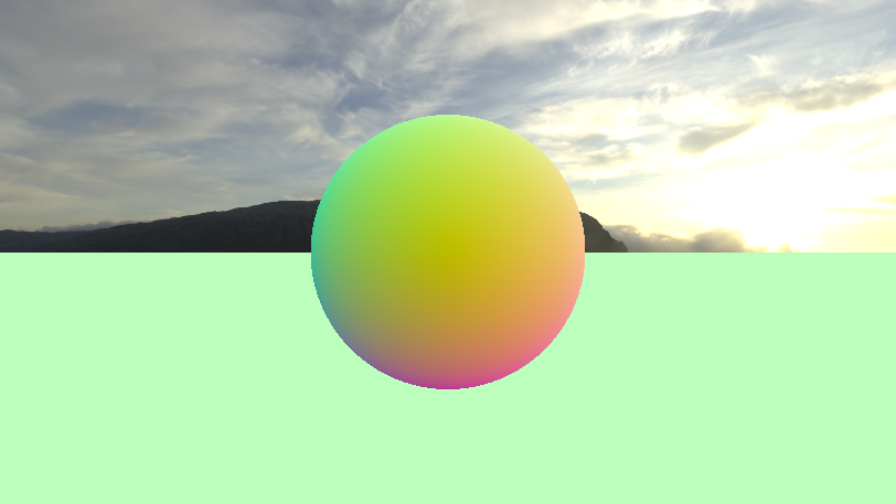
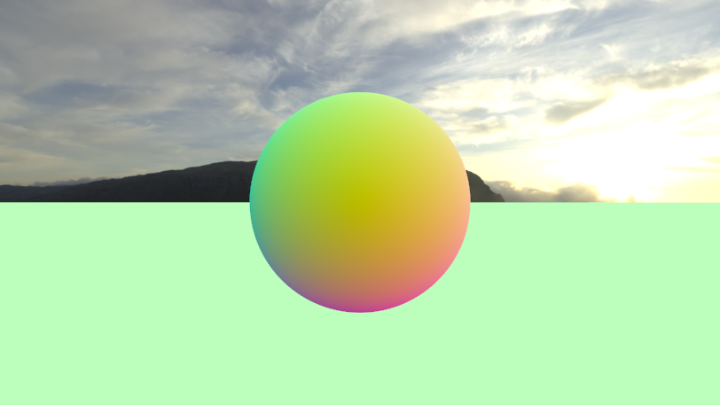
If you move the camera, you can see that the image is still visible distortion, but they quickly disappear, if you stand still a couple of frames. Here is a comparison of what we did:
The foundation for our ray tracer is ready, so we can proceed to the difficult things that actually distinguish ray tracing compared to other rendering techniques. First on this list are perfect reflections. The idea is simple: when we encounter a surface, we reflect the beam in accordance with the law of reflection, which you may remember from school (angle of incidence = angle of reflection), reduce its energy and repeat the process until the beam hits the sky, or he will not run out of energy after a specified number of reflections.
In the shader, add the
We will perform a maximum of 8 traces (source beam plus 7 reflections), and add the results in the
Our
HLSL has a built-in function to reflect the beam with a given normal, and this is convenient. Because of the inaccuracy of floating-point numbers, it may happen that the reflected beam is blocked by the surface from which it is reflected. To avoid this, we slightly shift the position along the normal direction. This is what the new
You can try to slightly increase the brightness of the skybox by multiplying it by a factor of more than 1. Now experiment with the

So, we can trace the specular reflections, which allows us to render smooth metal surfaces, but for non-metallic surfaces we need another property: diffuse reflection. In short, metals only reflect the incident light with a hint of their reflection color, and non-metals allow the light to be refracted on the surface, diffuse and leave it in a random direction, colored in the color of its albedo. In the case of an ideal Lamberto surface , which is commonly used, the probability is proportional to the cosine of the angle between the above direction and the normal of the surface. This topic is discussed in more detail here .
To get started with ambient lighting, let's add a
In the shader, define
Replace returned black values with simple diffuse shading:
Do not forget that the scalar product is defined as . Since both our vectors (the normal and the direction of light) are of unit length, we need exactly the scalar product: the cosine of the angle. The beam and the light have opposite directions, so under direct illumination the scalar product returns not 1, but -1. To accommodate this, we must change the sign. Finally, we saturate this value (for example, we limit it in the interval ) to avoid negative energy.
In order for the directional light source to cast shadows, we need to trace the shadow beam. It begins at the surface position considered (also with a very small offset to avoid self-shadowing), and points in the direction from which the light came. If something blocks its path to infinity, then we will not use ambient lighting. Add these lines above the diffuse color return:
Now we can trace the glossy plastic spheres with sharp shadows! If you set 0.04 for specular and 0.8 for albedo, then we get the following results:

Let's now start creating more complex and colorful scenes! Instead of a hard task of everything in the shader, for greater versatility, we will set the scene in C #.
To begin, we expand the
In order to understand in general what a sphere is in a CPU and a GPU, we define the struct
Copy this structure into a script in C #.
In the shader, we need to make the
Also set
Then define the
Now we breathe some life into the scene. Let's add common parameters to the C # script to control the location of the spheres and the compute buffer:
We will set up the scene in
The magic number 40
Congratulations, we did it! Now we have a ready-built Whitted ray tracer on the GPU, capable of rendering many spheres with specular reflections, simple diffused lighting and sharp shadows. The full source code is uploaded to Bitbucket . Experiment with the parameters of the placement of the spheres and watch the beautiful views:

Today we have achieved a lot, but much more can be realized: diffuse global illumination, soft shadows, partially transparent materials with refractions and, obviously, using triangles instead of spheres. In the next article, we will expand our Whitted ray tracer into the path tracer to master some of the listed phenomena.
In this article, we will write from scratch in Unity a very simple ray tracer using compute shaders. We will write scripts in C #, and shaders in HLSL. All code is laid out on Bitbucket .
As a result, we can render something like this:
')
Ray tracing theory
I want to start with a brief overview of the fundamentals of ray tracing. If you are familiar with it, you can safely skip this section.
Let's imagine how photographs appear in the real world — very simply, but this will be enough to explain the rendering. It all starts with a light source that emits photons. The photon flies in a straight line until it collides with the surface, after which it is reflected or refracted, and then continues its journey, losing some of the energy absorbed by the surface. Sooner or later, some of the photons get into the camera's sensor, which, in turn, creates the finished image. In essence, the ray tracing procedure imitates these steps to create photo-realistic images.
In practice, the camera will reach only a small fraction of the photons emitted by the light source. Therefore, thanks to the use of the Heimholz principle of reversibility, calculations are performed in the reverse order: instead of emitting photons from light sources, rays are emitted into the scene from the camera, reflected or refracted, and finally reach the light source.
The ray tracer that we will create is based on a 1980 article by Turner Whittedt . We can imitate sharp shadows and perfectly correct reflections. In addition, the tracer will serve as the basis for more complex effects, such as refraction, diffuse global illumination, brilliant reflections and soft shadows.
The basics
Let's start by creating a new Unity project. Create a C #
RayTracingMaster.cs script and a RayTracingMaster.cs compute shader. Paste the following base code into the C # script: using UnityEngine; public class RayTracingMaster : MonoBehaviour { public ComputeShader RayTracingShader; private RenderTexture _target; private void OnRenderImage(RenderTexture source, RenderTexture destination) { Render(destination); } private void Render(RenderTexture destination) { // Make sure we have a current render target InitRenderTexture(); // Set the target and dispatch the compute shader RayTracingShader.SetTexture(0, "Result", _target); int threadGroupsX = Mathf.CeilToInt(Screen.width / 8.0f); int threadGroupsY = Mathf.CeilToInt(Screen.height / 8.0f); RayTracingShader.Dispatch(0, threadGroupsX, threadGroupsY, 1); // Blit the result texture to the screen Graphics.Blit(_target, destination); } private void InitRenderTexture() { if (_target == null || _target.width != Screen.width || _target.height != Screen.height) { // Release render texture if we already have one if (_target != null) _target.Release(); // Get a render target for Ray Tracing _target = new RenderTexture(Screen.width, Screen.height, 0, RenderTextureFormat.ARGBFloat, RenderTextureReadWrite.Linear); _target.enableRandomWrite = true; _target.Create(); } } } The
OnRenderImage function OnRenderImage automatically called by Unity after the camera has finished rendering. To render, we first need to create a target render (render target) with the appropriate sizes and report this to the compute shader. 0 is the index of the compute shader kernel function - we have only one.Then we pass the shader. This means that we ask the GPU to do groups of threads that execute the code of our shader. Each stream group consists of several streams, the number of which is specified in the shader itself. The size and number of groups of threads can be specified in three dimensions, so you can simply apply compute shaders to tasks of any dimension. In our case, we need to create one thread per pixel of the target render. The default thread group size specified in the compute shader Unity template is
[numthreads(8,8,1)] , so we will stick to it and create one thread group for every 8 × 8 pixels. At the end we will write the result to the screen using Graphics.Blit .Let's check the program. Add a
RayTracingMaster component to the scene RayTracingMaster (this is important when calling OnRenderImage ), assign a compute shader and start the play mode. You should see the output of the compute shader Unity template as a beautiful triangular fractal.Camera
Now that we can display images on the screen, let's generate camera rays. Since Unity provides us with a fully functional camera, we can simply use the calculated matrices for this. Let's start by setting the matrices in the shader. Add the following lines to the
RayTracingMaster.cs script: private Camera _camera; private void Awake() { _camera = GetComponent<Camera>(); } private void SetShaderParameters() { RayTracingShader.SetMatrix("_CameraToWorld", _camera.cameraToWorldMatrix); RayTracingShader.SetMatrix("_CameraInverseProjection", _camera.projectionMatrix.inverse); } Before rendering, call
SetShaderParameters from OnRenderImage .In the shader, we define the matrices, the structure of the
Ray and the function to construct. It should be noted that in HLSL, unlike C #, the declaration of a function or variable must be performed before they are used. For the center of each screen pixel, we calculate the source and direction of the beam, and display the latter as a color. Here is what the whole shader looks like: #pragma kernel CSMain RWTexture2D<float4> Result; float4x4 _CameraToWorld; float4x4 _CameraInverseProjection; struct Ray { float3 origin; float3 direction; }; Ray CreateRay(float3 origin, float3 direction) { Ray ray; ray.origin = origin; ray.direction = direction; return ray; } Ray CreateCameraRay(float2 uv) { // Transform the camera origin to world space float3 origin = mul(_CameraToWorld, float4(0.0f, 0.0f, 0.0f, 1.0f)).xyz; // Invert the perspective projection of the view-space position float3 direction = mul(_CameraInverseProjection, float4(uv, 0.0f, 1.0f)).xyz; // Transform the direction from camera to world space and normalize direction = mul(_CameraToWorld, float4(direction, 0.0f)).xyz; direction = normalize(direction); return CreateRay(origin, direction); } [numthreads(8,8,1)] void CSMain (uint3 id : SV_DispatchThreadID) { // Get the dimensions of the RenderTexture uint width, height; Result.GetDimensions(width, height); // Transform pixel to [-1,1] range float2 uv = float2((id.xy + float2(0.5f, 0.5f)) / float2(width, height) * 2.0f - 1.0f); // Get a ray for the UVs Ray ray = CreateCameraRay(uv); // Write some colors Result[id.xy] = float4(ray.direction * 0.5f + 0.5f, 1.0f); } Try to rotate the camera in the inspector. You will see that the "colored sky" behaves accordingly.
Now let's replace the colors with a real skybox. In my examples, I will use Cape Hill from the HDRI Haven website, but you can of course choose any other. Download and drag it into Unity. In the import parameters, do not forget to increase the maximum resolution if the resolution of the downloaded file is more than 2048. Now add
public Texture SkyboxTexture to the script, assign the texture in the inspector and set it in the shader by adding this line to the SetShaderParameters function: RayTracingShader.SetTexture(0, "_SkyboxTexture", SkyboxTexture); In the shader, determine the texture and the corresponding sampler, as well as the constant that we will soon use:
Texture2D<float4> _SkyboxTexture; SamplerState sampler_SkyboxTexture; static const float PI = 3.14159265f; Now, instead of recording the color of the direction, we will sample the skybox. To do this, we transform the Cartesian direction vector into spherical coordinates and associate it with the texture coordinates.
CSMain last part of CSMain following: // Sample the skybox and write it float theta = acos(ray.direction.y) / -PI; float phi = atan2(ray.direction.x, -ray.direction.z) / -PI * 0.5f; Result[id.xy] = _SkyboxTexture.SampleLevel(sampler_SkyboxTexture, float2(phi, theta), 0); Tracing
So far so good. Now we get down to the ray tracing itself. Mathematically, we can calculate the intersection between the beam and the scene's geometry, and save the collision parameters (position, normal and distance along the beam). If our beam collides with several objects, we will select the closest one. Let's define in the shader struct
RayHit : struct RayHit { float3 position; float distance; float3 normal; }; RayHit CreateRayHit() { RayHit hit; hit.position = float3(0.0f, 0.0f, 0.0f); hit.distance = 1.#INF; hit.normal = float3(0.0f, 0.0f, 0.0f); return hit; } Usually scenes consist of many triangles, but we start with a simple one: from the intersection of the infinite plane of the earth and several spheres!
Ground plane
Calculate the intersection of a line with an infinite plane as - simple enough task. However, we consider only collisions in the positive direction of the beam and discard all collisions that are no closer than a potential previous collision.
By default, parameters in HLSL are passed by value, not by reference, so we will work only with a copy and will not be able to transfer changes to the calling function. We pass
RayHit bestHit with the inout qualifier to be able to modify the original struct. This is what the shader code looks like: void IntersectGroundPlane(Ray ray, inout RayHit bestHit) { // Calculate distance along the ray where the ground plane is intersected float t = -ray.origin.y / ray.direction.y; if (t > 0 && t < bestHit.distance) { bestHit.distance = t; bestHit.position = ray.origin + t * ray.direction; bestHit.normal = float3(0.0f, 1.0f, 0.0f); } } To use it, let's add the frame function
Trace (as we expand it): RayHit Trace(Ray ray) { RayHit bestHit = CreateRayHit(); IntersectGroundPlane(ray, bestHit); return bestHit; } In addition, we need a basic shading function. Here we transfer
Ray to inout again - we will change it later when we talk about reflections. For debugging purposes, we will return the normal when colliding with the geometry, and otherwise return to the skybox sampling code: float3 Shade(inout Ray ray, RayHit hit) { if (hit.distance < 1.#INF) { // Return the normal return hit.normal * 0.5f + 0.5f; } else { // Sample the skybox and write it float theta = acos(ray.direction.y) / -PI; float phi = atan2(ray.direction.x, -ray.direction.z) / -PI * 0.5f; return _SkyboxTexture.SampleLevel(sampler_SkyboxTexture, float2(phi, theta), 0).xyz; } } We will use both functions in
CSMain . Delete the skybox sampling code, if you have not already done so, and add the following lines to trace the ray and shade the collision: // Trace and shade RayHit hit = Trace(ray); float3 result = Shade(ray, hit); Result[id.xy] = float4(result, 1); Sphere
The plane is not the most interesting object in the world, so let's immediately add a sphere. Mathematical calculations of the intersection of a line and a sphere can be found on Wikipedia . This time we will have only two variants of the beam collisions: the input point
p1 - p2 and the output point p1 + p2 . First we will check the entry point, and use the exit point if the other does not fit. In our case, the sphere is defined as the value float4 , consisting of the position (xyz) and the radius (w). Here is what the code looks like: void IntersectSphere(Ray ray, inout RayHit bestHit, float4 sphere) { // Calculate distance along the ray where the sphere is intersected float3 d = ray.origin - sphere.xyz; float p1 = -dot(ray.direction, d); float p2sqr = p1 * p1 - dot(d, d) + sphere.w * sphere.w; if (p2sqr < 0) return; float p2 = sqrt(p2sqr); float t = p1 - p2 > 0 ? p1 - p2 : p1 + p2; if (t > 0 && t < bestHit.distance) { bestHit.distance = t; bestHit.position = ray.origin + t * ray.direction; bestHit.normal = normalize(bestHit.position - sphere.xyz); } } To add a sphere, simply call this function from
Trace , like this: // Add a floating unit sphere IntersectSphere(ray, bestHit, float4(0, 3.0f, 0, 1.0f)); Smoothing
The approach used has one problem: we check only the center of each pixel, so as a result, distortions will be noticeable (ugly "ladders"). To get around this problem, we will trace not one, but several rays per pixel. Each beam receives a random offset within the pixel region. To maintain an acceptable level of frame rate, we will perform progressive sampling, that is, trace one ray per pixel per frame and average the value over time if the camera is not moving. Every time the camera moves (or changes to any other parameters — the scope, scene geometry, or lighting) we’ll have to start all over again.
Let's create a very simple image effect shader, which we apply to add together several results.
AddShader call this shader AddShader and check that there is a Shader "Hidden/AddShader" in the first line. After Cull Off ZWrite Off ZTest Always add Blend SrcAlpha OneMinusSrcAlpha to enable alpha blending. Then replace the frag function with the following lines: float _Sample; float4 frag (v2f i) : SV_Target { return float4(tex2D(_MainTex, i.uv).rgb, 1.0f / (_Sample + 1.0f)); } Now this shader will simply draw the first sample with opacity following with opacity then and so on, averaging all samples with equal weight.
In the script, we need to count samples and apply an image effect shader:
private uint _currentSample = 0; private Material _addMaterial; Also, when rebuilding the target render in
InitRenderTexture we need to reset _currentSamples = 0 and add the Update function that recognizes the change in camera transformations: private void Update() { if (transform.hasChanged) { _currentSample = 0; transform.hasChanged = false; } } To use our shader, we need to initialize the material, inform it about the current sample and use it to insert it into the screen in the
Render function: // Blit the result texture to the screen if (_addMaterial == null) _addMaterial = new Material(Shader.Find("Hidden/AddShader")); _addMaterial.SetFloat("_Sample", _currentSample); Graphics.Blit(_target, destination, _addMaterial); _currentSample++; So, we are already performing progressive sampling, but still use the center of the pixel. In the compute shader, set the
float2 _PixelOffset and use it in CSMain instead of the hard-coded offset float2(0.5f, 0.5f) . Let's SetShaderParameters back to the script and create a random offset by adding the following line to SetShaderParameters : RayTracingShader.SetVector("_PixelOffset", new Vector2(Random.value, Random.value)); If you move the camera, you can see that the image is still visible distortion, but they quickly disappear, if you stand still a couple of frames. Here is a comparison of what we did:
Reflection
The foundation for our ray tracer is ready, so we can proceed to the difficult things that actually distinguish ray tracing compared to other rendering techniques. First on this list are perfect reflections. The idea is simple: when we encounter a surface, we reflect the beam in accordance with the law of reflection, which you may remember from school (angle of incidence = angle of reflection), reduce its energy and repeat the process until the beam hits the sky, or he will not run out of energy after a specified number of reflections.
In the shader, add the
float3 energy variable to the ray and initialize it in the CreateRay function as ray.energy = float3(1.0f, 1.0f, 1.0f) . Initially, the beam will have maximum values in all color channels, which will decrease with each reflection.We will perform a maximum of 8 traces (source beam plus 7 reflections), and add the results in the
Shade function calls, but multiplied by the beam energy. For example, imagine that the beam was reflected once and lost its energy. Then it continues to move and collides with the sky, so we only transfer to the pixel energy of the sky. Modify CSMain as follows, replacing previous calls to Trace and Shade : // Trace and shade float3 result = float3(0, 0, 0); for (int i = 0; i < 8; i++) { RayHit hit = Trace(ray); result += ray.energy * Shade(ray, hit); if (!any(ray.energy)) break; } Our
Shade function now also performs energy updating and generating a reflected beam, which is why inout becomes important here. To refresh the energy, we perform elementwise multiplication by the reflected color of the surface. For example, for gold, the specular reflection coefficient is approximately equal to float3(1.0f, 0.78f, 0.34f) , that is, it reflects 100% red, 78% green and only 34% blue, giving the reflection a characteristic golden hue. Be careful, none of these values should exceed 1, because otherwise the energy will be created from nowhere. In addition, reflectivity is often lower than one might think. For example, see some values on slide 64 in the article by Physics and Math of Shading by Netie Hofman.HLSL has a built-in function to reflect the beam with a given normal, and this is convenient. Because of the inaccuracy of floating-point numbers, it may happen that the reflected beam is blocked by the surface from which it is reflected. To avoid this, we slightly shift the position along the normal direction. This is what the new
Shade feature looks like: float3 Shade(inout Ray ray, RayHit hit) { if (hit.distance < 1.#INF) { float3 specular = float3(0.6f, 0.6f, 0.6f); // Reflect the ray and multiply energy with specular reflection ray.origin = hit.position + hit.normal * 0.001f; ray.direction = reflect(ray.direction, hit.normal); ray.energy *= specular; // Return nothing return float3(0.0f, 0.0f, 0.0f); } else { // Erase the ray's energy - the sky doesn't reflect anything ray.energy = 0.0f; // Sample the skybox and write it float theta = acos(ray.direction.y) / -PI; float phi = atan2(ray.direction.x, -ray.direction.z) / -PI * 0.5f; return _SkyboxTexture.SampleLevel(sampler_SkyboxTexture, float2(phi, theta), 0).xyz; } } You can try to slightly increase the brightness of the skybox by multiplying it by a factor of more than 1. Now experiment with the
Trace function. Put several spheres into the loop and the result will be as follows:Directional light source
So, we can trace the specular reflections, which allows us to render smooth metal surfaces, but for non-metallic surfaces we need another property: diffuse reflection. In short, metals only reflect the incident light with a hint of their reflection color, and non-metals allow the light to be refracted on the surface, diffuse and leave it in a random direction, colored in the color of its albedo. In the case of an ideal Lamberto surface , which is commonly used, the probability is proportional to the cosine of the angle between the above direction and the normal of the surface. This topic is discussed in more detail here .
To get started with ambient lighting, let's add a
public Light DirectionalLight to RayTracingMaster and set a directional light source in the scene. You may also need to recognize changes to the light source transformations in the Update function, as we did with the camera transformations. Now add the following lines to the SetShaderParameters function: Vector3 l = DirectionalLight.transform.forward; RayTracingShader.SetVector("_DirectionalLight", new Vector4(lx, ly, lz, DirectionalLight.intensity)); In the shader, define
float4 _DirectionalLight . In the Shade function, determine the color of the albedo immediately after the specular color: float3 albedo = float3(0.8f, 0.8f, 0.8f); Replace returned black values with simple diffuse shading:
// Return a diffuse-shaded color return saturate(dot(hit.normal, _DirectionalLight.xyz) * -1) * _DirectionalLight.w * albedo; Do not forget that the scalar product is defined as . Since both our vectors (the normal and the direction of light) are of unit length, we need exactly the scalar product: the cosine of the angle. The beam and the light have opposite directions, so under direct illumination the scalar product returns not 1, but -1. To accommodate this, we must change the sign. Finally, we saturate this value (for example, we limit it in the interval ) to avoid negative energy.
In order for the directional light source to cast shadows, we need to trace the shadow beam. It begins at the surface position considered (also with a very small offset to avoid self-shadowing), and points in the direction from which the light came. If something blocks its path to infinity, then we will not use ambient lighting. Add these lines above the diffuse color return:
// Shadow test ray bool shadow = false; Ray shadowRay = CreateRay(hit.position + hit.normal * 0.001f, -1 * _DirectionalLight.xyz); RayHit shadowHit = Trace(shadowRay); if (shadowHit.distance != 1.#INF) { return float3(0.0f, 0.0f, 0.0f); } Now we can trace the glossy plastic spheres with sharp shadows! If you set 0.04 for specular and 0.8 for albedo, then we get the following results:
Scene and materials
Let's now start creating more complex and colorful scenes! Instead of a hard task of everything in the shader, for greater versatility, we will set the scene in C #.
To begin, we expand the
RayHit structure in the shader. Instead of the global setting of material properties in the Shade function, we will define them for each object and store them in RayHit . Add float3 albedo and float3 specular to struct float3 albedo and initialize them with float3(0.0f, 0.0f, 0.0f) CreateRayHit in CreateRayHit . Also, change the Shade function so that it uses these values from hit instead of the hard-coded values. <In order to understand in general what a sphere is in a CPU and a GPU, we define the struct
Sphere in the shader and in the script in C #. From the side of the shader, it looks like this: struct Sphere { float3 position; float radius; float3 albedo; float3 specular; }; Copy this structure into a script in C #.
In the shader, we need to make the
IntersectSphere function work with our struct, and not with float4 . This is easy to do: void IntersectSphere(Ray ray, inout RayHit bestHit, Sphere sphere) { // Calculate distance along the ray where the sphere is intersected float3 d = ray.origin - sphere.position; float p1 = -dot(ray.direction, d); float p2sqr = p1 * p1 - dot(d, d) + sphere.radius * sphere.radius; if (p2sqr < 0) return; float p2 = sqrt(p2sqr); float t = p1 - p2 > 0 ? p1 - p2 : p1 + p2; if (t > 0 && t < bestHit.distance) { bestHit.distance = t; bestHit.position = ray.origin + t * ray.direction; bestHit.normal = normalize(bestHit.position - sphere.position); bestHit.albedo = sphere.albedo; bestHit.specular = sphere.specular; } } Also set
bestHit.albedo and bestHit.specular in the IntersectGroundPlane function to customize its material.Then define the
StructuredBuffer<Sphere> _Spheres . In this place the CPU will store all the spheres that make up the scene. Remove all hard-coded spheres from the Trace function and add the following lines: // Trace spheres uint numSpheres, stride; _Spheres.GetDimensions(numSpheres, stride); for (uint i = 0; i < numSpheres; i++) IntersectSphere(ray, bestHit, _Spheres[i]); Now we breathe some life into the scene. Let's add common parameters to the C # script to control the location of the spheres and the compute buffer:
public Vector2 SphereRadius = new Vector2(3.0f, 8.0f); public uint SpheresMax = 100; public float SpherePlacementRadius = 100.0f; private ComputeBuffer _sphereBuffer; We will set up the scene in
OnEnable and free the buffer in OnDisable . Thus, each time the component is turned on, a random scene will be generated.The function SetUpScenewill try to position the spheres in a certain radius and discard those that intersect existing ones. Half of the spheres are metallic (black albedo, colored specular), the other half is non-metallic (colored albedo, 4% specular): private void OnEnable() { _currentSample = 0; SetUpScene(); } private void OnDisable() { if (_sphereBuffer != null) _sphereBuffer.Release(); } private void SetUpScene() { List<Sphere> spheres = new List<Sphere>(); // Add a number of random spheres for (int i = 0; i < SpheresMax; i++) { Sphere sphere = new Sphere(); // Radius and radius sphere.radius = SphereRadius.x + Random.value * (SphereRadius.y - SphereRadius.x); Vector2 randomPos = Random.insideUnitCircle * SpherePlacementRadius; sphere.position = new Vector3(randomPos.x, sphere.radius, randomPos.y); // Reject spheres that are intersecting others foreach (Sphere other in spheres) { float minDist = sphere.radius + other.radius; if (Vector3.SqrMagnitude(sphere.position - other.position) < minDist * minDist) goto SkipSphere; } // Albedo and specular color Color color = Random.ColorHSV(); bool metal = Random.value < 0.5f; sphere.albedo = metal ? Vector3.zero : new Vector3(color.r, color.g, color.b); sphere.specular = metal ? new Vector3(color.r, color.g, color.b) : Vector3.one * 0.04f; // Add the sphere to the list spheres.Add(sphere); SkipSphere: continue; } // Assign to compute buffer _sphereBuffer = new ComputeBuffer(spheres.Count, 40); _sphereBuffer.SetData(spheres); } The magic number 40
new ComputeBuffer(spheres.Count, 40)is the step of our buffer, i.e. the size of one sphere in memory in bytes. To calculate it, let's calculate the number of float in a struct Sphereand multiply it by the byte size of float (4 bytes). Finally, set the shader buffer in the function SetShaderParameters: RayTracingShader.SetBuffer(0, "_Spheres", _sphereBuffer); results
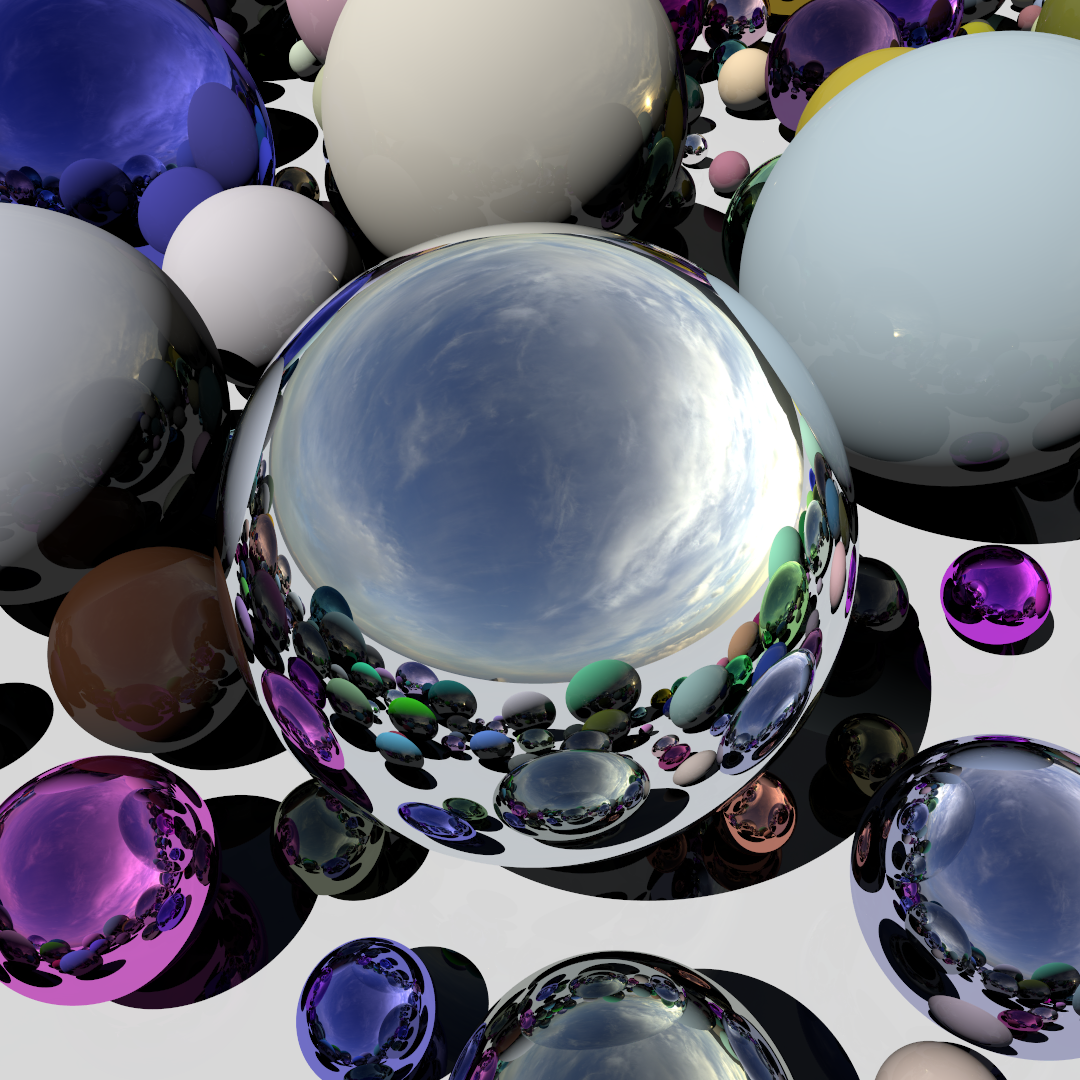
Congratulations, we did it! Now we have a ready-built Whitted ray tracer on the GPU, capable of rendering many spheres with specular reflections, simple diffused lighting and sharp shadows. The full source code is uploaded to Bitbucket . Experiment with the parameters of the placement of the spheres and watch the beautiful views:
What's next?
Today we have achieved a lot, but much more can be realized: diffuse global illumination, soft shadows, partially transparent materials with refractions and, obviously, using triangles instead of spheres. In the next article, we will expand our Whitted ray tracer into the path tracer to master some of the listed phenomena.
Source: https://habr.com/ru/post/355018/
All Articles