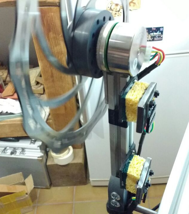
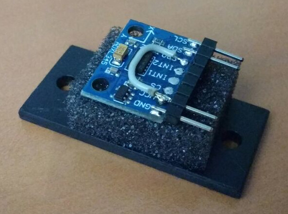
Two accelerometers, dish sponge and four nuts
Introductory: measuring the angle of the pendulum
So, having figured out the Hall sensors for brushless motors , I'll show you what it was for. I made a stand with a simple reverse pendulum, which is stabilized using a flywheel, which is rotated by a motor at the free end of the pendulum:
I study control theory and built a number of such toys, for example, my reverse pendulum on a trolley:
')
Analysis of the management of such things will leave on the next article, and the topic of today's article is the measurement of the angle of the pendulum. The easiest option is to install an incremental encoder, which I already explained in detail .
But in this article I want to measure the position of the pendulum using accelerometers attached to it. I will use the most penny adxl345. So, if we fasten the accelerometer to the pendulum at distance r from the hinge, how to determine the angle? I hooked up the accelerometer so that the Y axis was along the pendulum, and the X axis would be orthogonal to the pendulum:
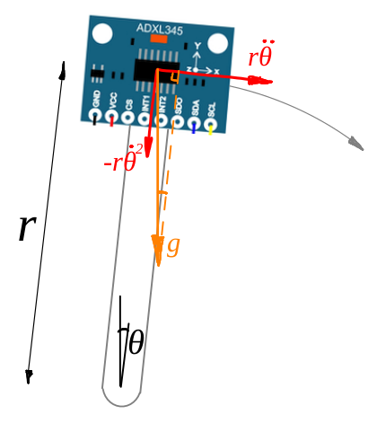
Let's assume for a start that the pendulum is not moving. Then the accelerometer will produce a projection of the gravity vector on its axis. Since everything happens in the same plane, ideally the accelerometer will produce zero values along the Z axis. That is, the accelerometer measurement will look like (x, y, z) = (g cos θ, –g sin θ, 0). Well, the angle can be obtained using arctangent from y / x.
If the accelerometer starts to move, then everything becomes a bit more difficult: in addition to the acceleration of free fall, it will also measure the angular acceleration of the pendulum and the corresponding centripetal acceleration, they are shown by the red arrows in the diagram.
I hung the accelerometer on a pendulum, and at the same time, for control, I started an incremental encoder, which gives me a real angle with which you can compare accelerometer measurements.
So, if I take the simplest arctangent from accelerometer measurements, I’ll get the following thing:
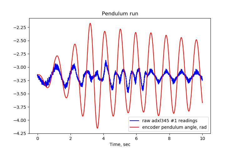
In this picture, I have a pendulum swinging around me, changing its true angle in time is a red curve, and the blue curve is the arctangent of y / x, they are also measurements of the accelerometer. It is clearly seen that the curves do not coincide.
And now let's add a second accelerometer, this time at a distance of r / 2 from the center. Two accelerometers will give us measurements (xa, ya) and (xb, yb), which (in the ideal case) should depend as follows on the angle θ and on the angular velocity / acceleration:

In principle, everything is rather prosaic, but why did I do that? And now the magic, watch your hands! Let's calculate what will be (xa, ya) - 2 * (xb, yb):

The whole dynamics of the pendulum itself is gone, leaving only the projection of the vector of the acceleration of free fall! That is, with the help of two accelerometers, we can estimate the angle of the pendulum, without looking at its dynamics:

This is the real-time estimate:
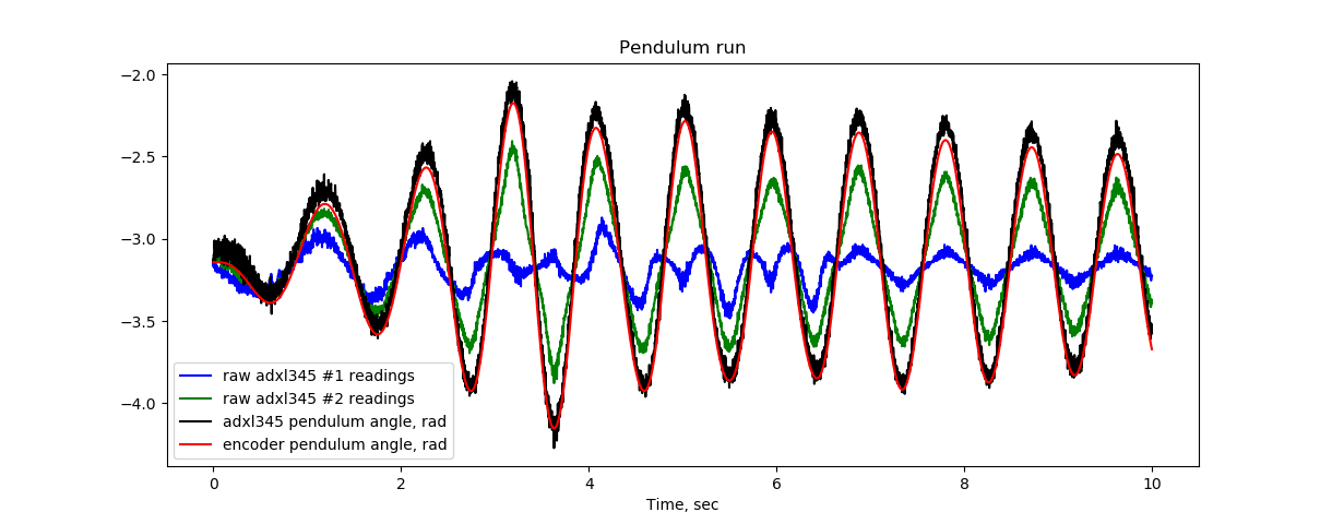
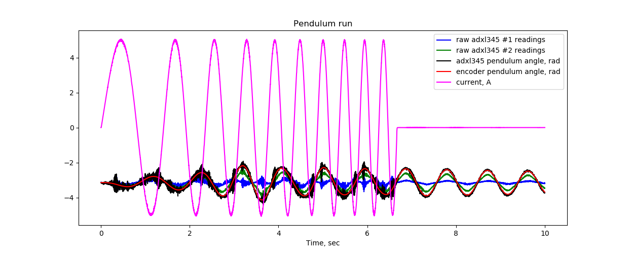
Here the blue and green curve is the raw data from the accelerometers, and the black curve is the calculated angle. It very well coincides with the reference curve obtained from the encoder. I did not adjust the sensors, everything was screwed “by eye”, from where there were small discrepancies between the data from accelerometers and from the encoder.
At this point, the story could be finished, but I promised a sponge for dishes (and four nuts!), Where are they? Will be now. This schedule was not obtained from the first approach. Let's start now from the beginning.
How to mount accelerometers
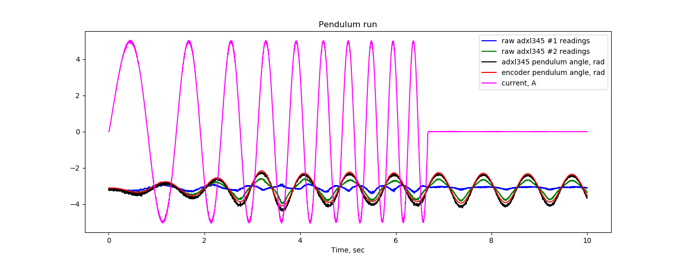
At first, I simply screwed the accelerometers to my pendulum and was unpleasantly surprised by the garbage that went as data. Let me show the scale of the disaster that I initially received:

This is the same schedule as the previous one, but added another pink curve, which gives the task of current in the little engine, which, in turn, pumps our flywheel. It turns out that when the motor works, the accelerometers give complete nonsense. But as soon as the motor turns off, everything magically returns to normal ... Why?
At first I sinned on the electro-fluxes, but it turned out that the high-frequency vibrations during the operation of the brushless engine are the culprit. Then I decided to do vibro-isolation. Never dealt with anything like this, only a soplemet was at hand. This is how my first vibration isolation looked like.
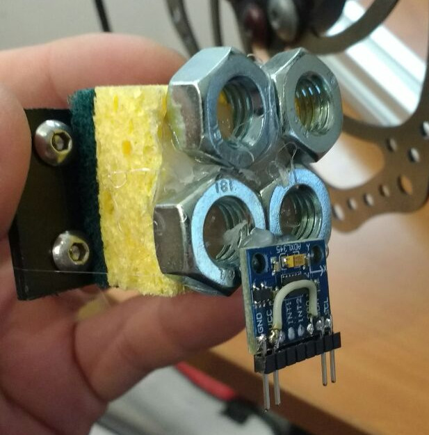
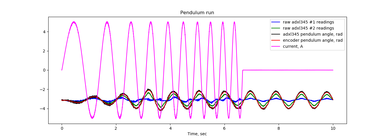
Nuts serve as an inertia damper. The first test, and the situation has improved dramatically! I rejoiced and skolkosil second version, where the nuts were replaced with a steel plate:
Here are the graphics:
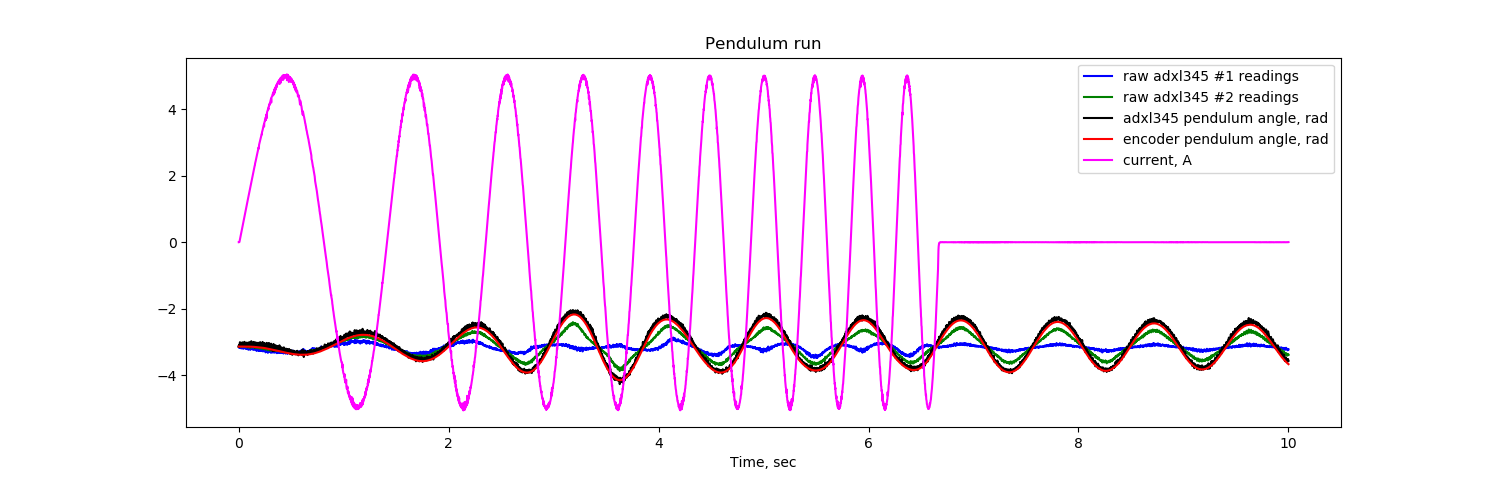
In principle, this could have calmed down, but it seemed to me that the thickness of the sponge, which introduced a fair delay during the rapid movements of the pendulum, seemed to be overkill. Therefore, I tried with another kitchen sponge:

Here are her graphics, the differences are visible in the region of the eighth or tenth second on a blue graph, which should be more or less triangular.
At this point, I was calmed down, but it turned out that I took a new sponge, which dried out in a couple of days so that it was not elastic enough. It would be possible to try to drop glycerin, but this is not our method! Therefore, I replaced the kitchen sponge with antistatic foam rubber:

Here are the relevant graphics:
And then the thought came to me: why am I even worried with the mass at all, is it possible to stick an axel directly onto the foam rubber? I tried the following configuration:
The answer is no, it is impossible!
In general, everything you wanted to know about low-pass filters, but were afraid to ask. Conclusion: vibration isolation is good, but it is necessary to correctly select the cut-off frequency. If someone can offer a less experimental method of selecting materials, their thickness and the corresponding goods, I will be very grateful!
Source: https://habr.com/ru/post/354950/
All Articles