Stm32f103 programming from the very beginning
In the article I would like to describe the steps towards writing firmware for stm32 microcontrollers without using special development environments like keil, eclipse and the like. I will describe the preparation of the firmware from the very basics, starting with writing a loader in assembler, a script for the linker and ending with the main program in C. In the C code, I will use the header files from CMSIS. The code editor can be any to your taste, vim, emacs, notepad, whatever. To build the project I will use the make utility. So, let's begin!
Why so harsh, you ask. First, in order to master something well, you need to start from the basics. I do not want my reader to thoughtlessly click the keys of the keyboard while typing the text of another super program for the device, not understanding how the device works. Stm32 is a much more complex microcontroller than, for example, atmega8 - atmega328 (a microcontroller installed on the most popular arduino board). Secondly, I like to understand myself from scratch in any business, and one can say this article is a note for me in the future to discover and recall some nuances.
Yes, I forgot to say that the development will be conducted under Linux. Any distribution kit will do, for example, I have this Arch Linux. For ubuntu, I will try to describe the process of installing the necessary utilities in the following sections. You can try Windows, MacOS, but for this you will have to figure out how to install the necessary utilities for compilation and firmware.
The first thing you need to do is to purchase a development board based on the stm32f103 controller. I have a blue pill:
')

Another thing to start is the st-link programmer:
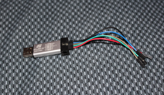
I bought the blue pill and the programmer on aliexpress, paying 200 rubles. for everything together.
The second thing you need to do is download the compilation kit for the code under the arm GNU GCC .
For arch linux, you must install the gcc-arm-none-eabi package:
Next we need the st-link utility to work with the st-link2 programmer of the same name:
Now let's try to connect our board to the computer through the programmer.
We connect the programmer with the blue pill board in this order:
So far, everything is very simple. Now we connect the programmer to the USB port of the computer, open the terminal and check that the device was successfully identified in the system:
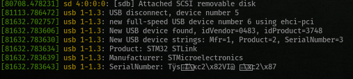
At the same time, two diodes will light up on the board itself, one red should be on permanently, which indicates that power is on, the second green should flash. This works the default firmware.
Now let's check the specifications of our demo board. To do this, run the st-info command from the stlink package installed before this in the terminal:
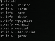
We can see the choice:
--version - the current version of the st-info utility
--flash - will display information about the size of the flash memory of the microcontroller's programs, in my case it is 0x10000 (65536 bytes)
--sram - the amount of static memory - 0x5000 (20480 bytes)
--descr - description - F1 Medium-density device
--pagesize - the size of the memory page - 0x400 (1024 bytes)
--hla-serial - "\ x30 \ x30 \ x30 \ x30 \ x30 \ x30 \ x30 \ x30 \ x30 \ x30 \ x30 \ x31"
--probe - Found 1 stlink programmers
serial: 303030303030303030303031
openocd: "\ x30 \ x30 \ x30 \ x30 \ x30 \ x30 \ x30 \ x30 \ x30 \ x30 \ x30 \ x31"
flash: 65536 (pagesize: 1024)
sram: 20480
chipid: 0x0410
descr: F1 Medium density device
What is important for us is the size of flash-memory and the size of static memory, and it is worth remembering that we have a Medium-density device.
Do not start development without documentation at hand. First, download the official Reference Manual website . It contains a complete description of all peripherals, microcontroller peripherals registers. Secondly, download the Programmer Manual for the same link. You will learn about the microprocessor of the STM32F10xxx / 20xxx / 21xxx / L1xxxx Cortex-M3 controller family, its architecture, set of commands.
Next, we analyze what the program starts on the microcontroller.
To calculate the initial location of the stack (the value for the SP register), refer to the Reference Manual manual on page 65. It indicates that RAM starts at 0x2000 0000. We previously determined that the microcontroller has a RAM size of 20,480 bytes:
That is, at the address 0x0800 0000 we must put the value 0x2000 5000.
At 0x0800 0004 we must put a pointer to the beginning of our program. Each pointer has a size of 4 bytes, so the next address for 0x0800 0004 in flash memory will be 0x0800 0004 + 4 = 0x0800 0008. This value should be placed at 0x0800 0004.
This is what the initial section of our firmware will look like:
Now about one feature of stm32 microcontrollers. The fact is that the format of commands for stm32 should be in the Thumb view instead of the standard ARM. This means that when pointing pointers, we must add 1. Remember this rule.
Enough theory, it's time to move on to practice. I hope you are still awake. Open your favorite code editor, we will write the initial file to start our controller. We will start with the startup file and it will be written in assembly language. This will be the only time when I force you to write in a boring assembler, but then you will begin to understand and “feel” the device from the inside.
We write at the very beginning:
This is a comment in assembly language, each comment starts with an @ symbol.
Next, we indicate the assembler directives
And then a short bootstrap program:
You can download the entire program at https://bit.ly/2rc7bcf
Save it under the name bootstrap.s.
And now let's compile and fix our board.
First of all, I'll show you how to download the default firmware from your board, the one that flashes the LED. Suddenly ever come in handy.
Again, insert the programmer with the connected board in usb and run the command in the Linux terminal:
Here we indicate that we want to read the flash memory into the file default.bin starting at address 0x08000000 and size 0x10000 (64K), that is, the entire flash memory.
st-flash is a utility for working with microcontroller firmware, read its full description in the terminal:
After that, check that the firmware was correctly considered. Load it again, overwriting the old one.
What does it mean to write default.bin to the controller's flash memory starting at address 0x08000000.
Remove and reinsert the programmer, the green diode on the board should flash as before.
Now let's compile our self-written firmware. In the terminal in the same directory as saved, run:
Here we compile our source file into object code. This is not yet ready firmware, suitable for pouring into the microcontroller. We also need to “specify” where, at what addresses to place our program. The linker does this. We will use the most popular LD linker that comes with the arm-none-eabi-gcc package. In more detail about the linker and the description of the script for the linker ld, I will discuss in the next section, when we proceed to the automatic assembly of our super-simple firmware. For now, just download this small stm32f103.ld file https://bit.ly/2HXIydu , and run the command:
With this command we compose our object file with the help of the stm32f103.ld script, we get an elf file at the output.
To finally prepare the executable elf file for the firmware, execute the last command:
Here we convert the elf file into a pure binary format suitable for uploading to our board.
So, our first program for stm32 controller is ready! Stitch!
Congratulations! Now the microcontroller is doomed to the eternal implementation of an unconditional transition. See you next time!
Why so harsh, you ask. First, in order to master something well, you need to start from the basics. I do not want my reader to thoughtlessly click the keys of the keyboard while typing the text of another super program for the device, not understanding how the device works. Stm32 is a much more complex microcontroller than, for example, atmega8 - atmega328 (a microcontroller installed on the most popular arduino board). Secondly, I like to understand myself from scratch in any business, and one can say this article is a note for me in the future to discover and recall some nuances.
Yes, I forgot to say that the development will be conducted under Linux. Any distribution kit will do, for example, I have this Arch Linux. For ubuntu, I will try to describe the process of installing the necessary utilities in the following sections. You can try Windows, MacOS, but for this you will have to figure out how to install the necessary utilities for compilation and firmware.
The first thing you need to do is to purchase a development board based on the stm32f103 controller. I have a blue pill:
')
Another thing to start is the st-link programmer:
I bought the blue pill and the programmer on aliexpress, paying 200 rubles. for everything together.
The second thing you need to do is download the compilation kit for the code under the arm GNU GCC .
For arch linux, you must install the gcc-arm-none-eabi package:
yaourt -Syy arm-none-eabi-gcc Next we need the st-link utility to work with the st-link2 programmer of the same name:
yaourt -Syy stlink Now let's try to connect our board to the computer through the programmer.
We connect the programmer with the blue pill board in this order:
- Connect to GND pin (ground - ground, pin two, take any, for example, 4th) on the programmer wire (it is desirable to follow some standards, for the earth, use black or blue) and connect to the pin on the board signed GND;
- Connect the SWCLK pin (clock - synchronization) on the programmer to the SWCLK pin on the board;
- Connect the SWDIO pin (IO - input / input) on the programmer to the SWIO pin on the board;
- Finally, connect the 3.3V pin on the programmer with the pin 3.3V on the board.
So far, everything is very simple. Now we connect the programmer to the USB port of the computer, open the terminal and check that the device was successfully identified in the system:
dmesg At the same time, two diodes will light up on the board itself, one red should be on permanently, which indicates that power is on, the second green should flash. This works the default firmware.
Now let's check the specifications of our demo board. To do this, run the st-info command from the stlink package installed before this in the terminal:
We can see the choice:
--version - the current version of the st-info utility
--flash - will display information about the size of the flash memory of the microcontroller's programs, in my case it is 0x10000 (65536 bytes)
--sram - the amount of static memory - 0x5000 (20480 bytes)
--descr - description - F1 Medium-density device
--pagesize - the size of the memory page - 0x400 (1024 bytes)
--hla-serial - "\ x30 \ x30 \ x30 \ x30 \ x30 \ x30 \ x30 \ x30 \ x30 \ x30 \ x30 \ x31"
--probe - Found 1 stlink programmers
serial: 303030303030303030303031
openocd: "\ x30 \ x30 \ x30 \ x30 \ x30 \ x30 \ x30 \ x30 \ x30 \ x30 \ x30 \ x31"
flash: 65536 (pagesize: 1024)
sram: 20480
chipid: 0x0410
descr: F1 Medium density device
What is important for us is the size of flash-memory and the size of static memory, and it is worth remembering that we have a Medium-density device.
Do not start development without documentation at hand. First, download the official Reference Manual website . It contains a complete description of all peripherals, microcontroller peripherals registers. Secondly, download the Programmer Manual for the same link. You will learn about the microprocessor of the STM32F10xxx / 20xxx / 21xxx / L1xxxx Cortex-M3 controller family, its architecture, set of commands.
Next, we analyze what the program starts on the microcontroller.
- Immediately after switching on, our microcontroller stm32f103c8 begins to read at 0x08000000 (for convenience of reading, I will divide the tetrads with a space - 0x0800 0000) the value for the SP register. SP (Stack pointer) - the stack pointer register (p. 15 Programmer Manual). The stack starts at the end of available RAM and grows “up”;
- At address 0x0800 0004 reads the value in the PC register - Program counter. This value is the address of the entry point to our main program, in other words at the address 0x0800 0004 flash should be the address of the C - main () function defined by us later;
- The microcontroller starts the execution of the program.
To calculate the initial location of the stack (the value for the SP register), refer to the Reference Manual manual on page 65. It indicates that RAM starts at 0x2000 0000. We previously determined that the microcontroller has a RAM size of 20,480 bytes:
0x2000 0000 + 0x5000 = 0x2000 5000That is, at the address 0x0800 0000 we must put the value 0x2000 5000.
At 0x0800 0004 we must put a pointer to the beginning of our program. Each pointer has a size of 4 bytes, so the next address for 0x0800 0004 in flash memory will be 0x0800 0004 + 4 = 0x0800 0008. This value should be placed at 0x0800 0004.
This is what the initial section of our firmware will look like:
+-------------+-------------+ | flash | | +-------------+-------------+ | 0x0800 0000 | 0x2000 5000 | | 0x0800 0004 | 0x0800 0008 | +-------------+-------------+ Now about one feature of stm32 microcontrollers. The fact is that the format of commands for stm32 should be in the Thumb view instead of the standard ARM. This means that when pointing pointers, we must add 1. Remember this rule.
Enough theory, it's time to move on to practice. I hope you are still awake. Open your favorite code editor, we will write the initial file to start our controller. We will start with the startup file and it will be written in assembly language. This will be the only time when I force you to write in a boring assembler, but then you will begin to understand and “feel” the device from the inside.
We write at the very beginning:
@stm32f103 This is a comment in assembly language, each comment starts with an @ symbol.
Next, we indicate the assembler directives
.syntax unified @ stm32 - Thumb! .thumb @ cortex-m3 @( ) .cpu cortex-m3 And then a short bootstrap program:
@ . !
@.equ
@ define C
@,
.equ StackPointer 0x20005000

@.word - , - 4
@ (0x0800 0000)
@
.word StackPointer

@”” .
@Reset - , .
@ , Thumb,
@
.word Reset + 1

@ Reset. ,
@ ,
@ . B -
@ ARM,
@ JMP x86,
@ goto .
@ B - ,
@ Reset, .
Reset: B Reset
You can download the entire program at https://bit.ly/2rc7bcf
Save it under the name bootstrap.s.
And now let's compile and fix our board.
First of all, I'll show you how to download the default firmware from your board, the one that flashes the LED. Suddenly ever come in handy.
Again, insert the programmer with the connected board in usb and run the command in the Linux terminal:
st-flash read ./default.bin 0x08000000 0x10000 Here we indicate that we want to read the flash memory into the file default.bin starting at address 0x08000000 and size 0x10000 (64K), that is, the entire flash memory.
st-flash is a utility for working with microcontroller firmware, read its full description in the terminal:
st-flash --help .After that, check that the firmware was correctly considered. Load it again, overwriting the old one.
st-flash write ./default.bin 0x08000000 What does it mean to write default.bin to the controller's flash memory starting at address 0x08000000.
Remove and reinsert the programmer, the green diode on the board should flash as before.
Now let's compile our self-written firmware. In the terminal in the same directory as saved, run:
arm-none-eabi-as -o bootstrap.o bootstrap.s Here we compile our source file into object code. This is not yet ready firmware, suitable for pouring into the microcontroller. We also need to “specify” where, at what addresses to place our program. The linker does this. We will use the most popular LD linker that comes with the arm-none-eabi-gcc package. In more detail about the linker and the description of the script for the linker ld, I will discuss in the next section, when we proceed to the automatic assembly of our super-simple firmware. For now, just download this small stm32f103.ld file https://bit.ly/2HXIydu , and run the command:
arm-none-eabi-ld -o main.elf -T stm32f103.ld bootstrap.o With this command we compose our object file with the help of the stm32f103.ld script, we get an elf file at the output.
To finally prepare the executable elf file for the firmware, execute the last command:
arm-none-eabi-objcopy main.elf main.bin -O binary Here we convert the elf file into a pure binary format suitable for uploading to our board.
So, our first program for stm32 controller is ready! Stitch!
st-flash write ./main.bin 0x08000000 Congratulations! Now the microcontroller is doomed to the eternal implementation of an unconditional transition. See you next time!
Source: https://habr.com/ru/post/354670/
All Articles