Visualization in CAD: why we wrote another 3D engine and how it works
Since 1995, the C3D Labs team has been making a geometric core, a key technological component for the creation of computer-aided design (CAD) systems. Two years ago we released our own visualization module, C3D Vision. Why did you need another 3D engine?

Rendering for a CAD developer is always fraught with certain difficulties. If you take ready-made commercial or open-source visualizers, most of them were originally created for the gaming industry and do not meet the specifics of engineering CAD / CAM / CAE applications.
Game engines work with textures, sprites, animations. And engineering applications first need tools to work with geometry:
')
We called three important tools for CAD, which are missing in the game engines, but they are much more.
Not all developers can write their own engine. Expensive, long and distracting from the main product. So there was a natural request for specialized engines for CAD. In the world there are such, for example Hoops, Redway, but they are quite expensive, in addition, they require integration with already developed geometric cores. Because the best visualizer is the one that works together with the used mathematical core as a whole.
Until 2016, we did not have our own engine. We offered developers a core
geometric modeling (a “brain” for CAD), a geometric constraint solver, and a data exchange module. And questions about the visualization we were asked regularly. Customers wanted to get the engine along with the kernel, and not to engage in the integration of a third-party component. So the decision was born to write your own engine, especially since at that time no company supplied the full set of components for creating CAD systems. And now we are the only ones who develop all four components: the core, the solver, the converter and the visualizer. At the same time, our 3D engine can be used as an independent module with components from other developers.
Indeed, the OpenGL specification is used for visualization in many CAD systems, but it has serious disadvantages. For all its capabilities, it does not have a structural API for describing the scene, and its interface provides only the basic tools for three-dimensional rendering. This makes it very difficult for developers to use the OpenGL API without using auxiliary code, which is usually implemented on its own and requires a lot of time and resources. We have proposed a higher-level tool that provides developers with certain means of structural description of the visualization scene, and also has a set of necessary tools for interactive interaction with the scene.
We took into account that the OpenGL standard is not related to the window system and is widely distributed in open systems. The OpenGL specification uses the GLX extension, which belongs to the core protocol of the X Window System and provides interoperability between the OpenGL and the X Window. This extension organizes direct rendering bypassing the X server, which allows you to implement efficient applications running in a distributed X environment. All these features are used in our visualizer.
C3D Vision is a set of functional "bricks" from which full-fledged graphic applications are built with minimal effort. Our visualizer has the ability to scale the architecture, thanks to which the developer can create his own classes of objects, inheriting them from the existing ones, and thus laying their own properties and rules in them. As required, you can set classes up to the drawing representation of the object in the scene.
Graphic applications created on the basis of C3D Vision work with the geometric representations of the scene, namely, segments, surfaces, edges and other objects that are drawn in the active window. The direct interaction of the user with the graphic application has a certain representation of the scene display. If the representation does not have a hierarchical structure, but suppose it is represented by a simple linear array of objects, then this makes it difficult to use effective methods, such as cutting off invisible objects or searching for objects of the scene.
The use of a scene representation with a hierarchical structure provides several advantages. In this case, the functionality of the objects of the scene is very similar and they can be divided into separate groups, which are combined into groups of a higher level. In turn, the application of hierarchical principles inevitably leads to the well-known graphic standard PHIGS (Programmer's Hierarchical Interactive Graphics System).
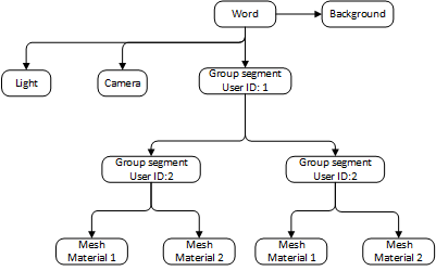
Generalized scheme of the scene in C3D Vision (the image is clickable)
It is the hierarchical principles that were applied in the development of the 3D engine, so the scene description in it is represented as a graph having terminal nodes or groups of nodes as objects. Since in such a representation of the scene segments act as nodes in the graph, we introduced the definition of “segmentation of the scene”. A segment that does not have a parent is called a root (from English - root). Segments can be grouped by properties: materials, forms, etc. In addition, it is possible to create a set of segments, in particular template groups, the lifetime of which is determined by the user. This could be a set of manipulators, pre-created for editing certain segments, or something else.
The scene graph belongs to the container, which has a number of necessary functions for working with the graph, as well as the drawing channel. But, perhaps, one of the most important characteristics of C3D Vision is that the user is in no way limited to creating many such containers. It can form several independent graphs that differ in the whole list of significant criteria.
This approach ensures high flexibility in the work of the visualizer and allows you to fine-tune it in detail to ensure maximum rendering performance.
The use of scene segmentation is caused not only by the convenience of working with objects divided into components, but also by the need to accomplish other tasks, including:
In order for the developer to work with objects on a specific pattern and to have the opportunity, if necessary, to create their own types of objects, we implemented the segmentation of the scene in the form of a directed acyclic graph. Such a graph organization allows you to create a logical representation of the scene for more efficient rendering.
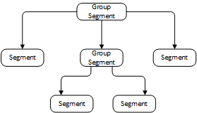
Presentation of the scene as a directed acyclic graph (the image is clickable)
Segments of the graph can contain geometric data or a link to this data for their subsequent drawing, while the use of reference geometry provides a very significant savings in operational and video memory. Intermediate segments of the graph allow you to group sub-segments and perform certain actions on them. Each graph segment has its own transformation matrix, affecting all incoming subsegments. By changing this matrix, you can change the location of the geometry in space: rotate, shift, etc.
Each segment of the scene graph has its own coordinate system, while the matrix of the segment transforms the polygonal models that are specified in the coordinate systems of the sub-segments into their own coordinate system of the segment in question. Since the product of all matrices from the current segment to the root segment of the scene graph forms a transformation matrix from the local coordinate system of the current segment to the world coordinate system, in the considered case the global coordinate system will be associated with the root segment. As an example of scene segmentation, let us show the drawing of a 3D model of an excavator with a swinging turret and a lifting rotor.

Model of a rotary excavator with a rotary turret and a lifting tool: 1 - tracked platform; 2 - slewing gear; 3 - turntable; 4 - counterweight; 5 - tower; 6 - cab; 7 - rotary working body
Based on the model of the excavator, we reproduce the scene graph. We take only large mechanisms 1-3-4-5, that is, we produce a segmentation of the scene according to key fragments.
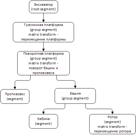
Segmentation of the rotor excavator scene (clickable image)
It can be seen that the tracked platform segment is inherited from the root segment and contains a displacement matrix. With the transformation of movement, the change of this matrix will affect all subsegments, therefore the excavator will move along the direction of travel. Accordingly, the transformation of the turntable matrix will rotate the entire group, including subsegments. A group of segments that form a subgraph of the entire graph of a scene can be considered as a separate object consisting of a set of incoming objects. For example, a car with seats can be represented as an indivisible object, although in reality it consists of many geometric objects.
With this approach, you can solve a number of useful tasks for managing the location of objects inside the scene. It is enough to transform the matrix of one intermediate segment so that the position in the scene at once changes for all incoming segments and, therefore, for all geometry. If the task of moving a car is solved, then all the contents in it - the seats, the steering wheel, the pedals, the driver with the passengers - also move without organizing any obstacles for performing other local tasks. It should be emphasized here that any actions on a segment mainly apply to its subsegments.
Let us dwell on reference geometry. The scene graph usually includes a large number of subgraphs, and those, in turn, are several descendants that form child subgraphs. Finally, the latter can have their own geometry. If we consider the set of all existing models, it becomes obvious that most of them do not differ in geometry. The same car has four wheels of the same shape and size, therefore it is rational to store such geometry in one copy, and to determine the differences in the location of the wheels to use individual matrices. In C3D Vision, we implemented the ability to assign geometry references to a particular segment of the scene graph.

Scene segmentation using reference geometry (clickable image)
One of the most important properties of a scene graph is storing the display state of each segment. In this case we are talking about preparing OpenGL before drawing on other segment properties, such as textures, shaders, and materials. The assignment of a number of properties of a segment extends to subsegments, that is, to the entire subgraph.
With the help of segmentation of the scene, you can solve some global problems related to the entire graph of the scene as a whole. The first is the optimization of rendering. The more objects you need to draw, the more computer time it will take to calculate and display the scene changes on the monitor.
For a long period of time, a large number of objects are located outside the screen area or inside other objects. Therefore, the calculation of such objects can be neglected, making them invisible and simply removing from the output to the screen. This will have a positive effect on the rendering performance of the scene, because if the object is not within the scope of the virtual camera, then there is no need to send it to the drawing in the video adapter.
Using the scene graph, you can easily find such objects. To do this, a bounded rectangle or sphere is calculated in each segment. Next, all child subgraphs and segments are added to it, and just before drawing the scene, the intersection of the bounding sphere of the scene segment with the so-called visibility pyramid is calculated. As a result, a sorted list of all visible segments of the scene graph is constructed. This mechanism for cutting off minor elements of the scene is characteristic of the Frustum Culling optimization mode.
The realization of light in C3D Vision fulfills the same role as real light sources, since it makes objects visible. It is the light sources that determine which part of the model will participate in the projection of the scene on the plane, whether it be a computer screen or a mobile phone display. There can be several sources of illumination, and the corresponding C3D Vision objects can simulate various lighting effects. All objects are modeled based on the behavior of real light sources. An important feature is that the scene must have at least one light source in order for the objects of the virtual scene to become visible.
To date, C3D Vision has several types of lighting sources:
Most people perceive the image as the space reflected in the viewfinder of the virtual camera. But in the OpenGL implementation of this kind of camera does not exist. Therefore, in order to form the illusion of movement or rotation in the scene relative to the viewer, such an implementation must be created.
With the camera in C3D Vision, you can get almost any image. A camera is a device that captures and displays the world to the observer. By manipulating through the presented camera functionality, you can set unique settings and actions, in particular, rotation around the entire scene in orbit or relative to the origin, panning, zooming, rotation around the axis of the view, etc.
Our visualizer has a number of tools to control the location of the camera. All of these tools are descendants of the library class Process, which accepts mouse and keyboard events and interprets user actions while working with these devices as actions directly with the camera. In addition to the implementation of ready-made tools, the developer is given the opportunity to create on the basis of the Process class his own software tools necessary for controlling the camera.
An important feature of C3D Vision is the ability to scale the program code, create custom objects by the user, and interactive processes to expand the instrumental capabilities of the source library. The visualizer is based on our geometric core C3D Modeler. This means that when using the mathematical part of the C3D Toolkit component set in a project, its interfacing with C3D Vision objects is directly supported, which makes it much easier for developers to create their own applications.
We did not consider in detail the support of shaders, the selection of scene objects and their detailing using LOD technology, the support of translucent objects, pixel culling - all this our visualization module is also able to do.
We are currently working on its second version. It will have new tools and features focused on computer-aided design.
Interested developers can test C3D Vision. The module is provided free of charge for three months, upon request on our website.
 Edward Maksimenko, Ph.D., Head of Development C3D Vision
Rendering for a CAD developer is always fraught with certain difficulties. If you take ready-made commercial or open-source visualizers, most of them were originally created for the gaming industry and do not meet the specifics of engineering CAD / CAM / CAE applications.
Game engines work with textures, sprites, animations. And engineering applications first need tools to work with geometry:
')
- locators - convert the screen coordinates of the cursor into the current geometric object
- bindings (snap) - calculate the exact coordinates of a geometric object
- tugs-manipulators - allow an interactive way to interact with the model that will be built.
We called three important tools for CAD, which are missing in the game engines, but they are much more.
Not all developers can write their own engine. Expensive, long and distracting from the main product. So there was a natural request for specialized engines for CAD. In the world there are such, for example Hoops, Redway, but they are quite expensive, in addition, they require integration with already developed geometric cores. Because the best visualizer is the one that works together with the used mathematical core as a whole.
Until 2016, we did not have our own engine. We offered developers a core
geometric modeling (a “brain” for CAD), a geometric constraint solver, and a data exchange module. And questions about the visualization we were asked regularly. Customers wanted to get the engine along with the kernel, and not to engage in the integration of a third-party component. So the decision was born to write your own engine, especially since at that time no company supplied the full set of components for creating CAD systems. And now we are the only ones who develop all four components: the core, the solver, the converter and the visualizer. At the same time, our 3D engine can be used as an independent module with components from other developers.
Why not opengl?
Indeed, the OpenGL specification is used for visualization in many CAD systems, but it has serious disadvantages. For all its capabilities, it does not have a structural API for describing the scene, and its interface provides only the basic tools for three-dimensional rendering. This makes it very difficult for developers to use the OpenGL API without using auxiliary code, which is usually implemented on its own and requires a lot of time and resources. We have proposed a higher-level tool that provides developers with certain means of structural description of the visualization scene, and also has a set of necessary tools for interactive interaction with the scene.
We took into account that the OpenGL standard is not related to the window system and is widely distributed in open systems. The OpenGL specification uses the GLX extension, which belongs to the core protocol of the X Window System and provides interoperability between the OpenGL and the X Window. This extension organizes direct rendering bypassing the X server, which allows you to implement efficient applications running in a distributed X environment. All these features are used in our visualizer.
Data Visualization in C3D Vision
C3D Vision is a set of functional "bricks" from which full-fledged graphic applications are built with minimal effort. Our visualizer has the ability to scale the architecture, thanks to which the developer can create his own classes of objects, inheriting them from the existing ones, and thus laying their own properties and rules in them. As required, you can set classes up to the drawing representation of the object in the scene.
Graphic applications created on the basis of C3D Vision work with the geometric representations of the scene, namely, segments, surfaces, edges and other objects that are drawn in the active window. The direct interaction of the user with the graphic application has a certain representation of the scene display. If the representation does not have a hierarchical structure, but suppose it is represented by a simple linear array of objects, then this makes it difficult to use effective methods, such as cutting off invisible objects or searching for objects of the scene.
The use of a scene representation with a hierarchical structure provides several advantages. In this case, the functionality of the objects of the scene is very similar and they can be divided into separate groups, which are combined into groups of a higher level. In turn, the application of hierarchical principles inevitably leads to the well-known graphic standard PHIGS (Programmer's Hierarchical Interactive Graphics System).
Generalized scheme of the scene in C3D Vision (the image is clickable)
It is the hierarchical principles that were applied in the development of the 3D engine, so the scene description in it is represented as a graph having terminal nodes or groups of nodes as objects. Since in such a representation of the scene segments act as nodes in the graph, we introduced the definition of “segmentation of the scene”. A segment that does not have a parent is called a root (from English - root). Segments can be grouped by properties: materials, forms, etc. In addition, it is possible to create a set of segments, in particular template groups, the lifetime of which is determined by the user. This could be a set of manipulators, pre-created for editing certain segments, or something else.
The scene graph belongs to the container, which has a number of necessary functions for working with the graph, as well as the drawing channel. But, perhaps, one of the most important characteristics of C3D Vision is that the user is in no way limited to creating many such containers. It can form several independent graphs that differ in the whole list of significant criteria.
This approach ensures high flexibility in the work of the visualizer and allows you to fine-tune it in detail to ensure maximum rendering performance.
The use of scene segmentation is caused not only by the convenience of working with objects divided into components, but also by the need to accomplish other tasks, including:
- changing segment parameters — moving and rotating objects, switching and checking visibility, setting materials and light sources, etc.
- rebuilding the model tree in any convenient way - creating and deleting segments or merging with other graph segments
- traversing the scene graph to perform the necessary actions for each segment
- drawing the whole scene with OpenGL.
Scene segmentation
In order for the developer to work with objects on a specific pattern and to have the opportunity, if necessary, to create their own types of objects, we implemented the segmentation of the scene in the form of a directed acyclic graph. Such a graph organization allows you to create a logical representation of the scene for more efficient rendering.
Presentation of the scene as a directed acyclic graph (the image is clickable)
Segments of the graph can contain geometric data or a link to this data for their subsequent drawing, while the use of reference geometry provides a very significant savings in operational and video memory. Intermediate segments of the graph allow you to group sub-segments and perform certain actions on them. Each graph segment has its own transformation matrix, affecting all incoming subsegments. By changing this matrix, you can change the location of the geometry in space: rotate, shift, etc.
Each segment of the scene graph has its own coordinate system, while the matrix of the segment transforms the polygonal models that are specified in the coordinate systems of the sub-segments into their own coordinate system of the segment in question. Since the product of all matrices from the current segment to the root segment of the scene graph forms a transformation matrix from the local coordinate system of the current segment to the world coordinate system, in the considered case the global coordinate system will be associated with the root segment. As an example of scene segmentation, let us show the drawing of a 3D model of an excavator with a swinging turret and a lifting rotor.
Model of a rotary excavator with a rotary turret and a lifting tool: 1 - tracked platform; 2 - slewing gear; 3 - turntable; 4 - counterweight; 5 - tower; 6 - cab; 7 - rotary working body
Based on the model of the excavator, we reproduce the scene graph. We take only large mechanisms 1-3-4-5, that is, we produce a segmentation of the scene according to key fragments.
Segmentation of the rotor excavator scene (clickable image)
It can be seen that the tracked platform segment is inherited from the root segment and contains a displacement matrix. With the transformation of movement, the change of this matrix will affect all subsegments, therefore the excavator will move along the direction of travel. Accordingly, the transformation of the turntable matrix will rotate the entire group, including subsegments. A group of segments that form a subgraph of the entire graph of a scene can be considered as a separate object consisting of a set of incoming objects. For example, a car with seats can be represented as an indivisible object, although in reality it consists of many geometric objects.
With this approach, you can solve a number of useful tasks for managing the location of objects inside the scene. It is enough to transform the matrix of one intermediate segment so that the position in the scene at once changes for all incoming segments and, therefore, for all geometry. If the task of moving a car is solved, then all the contents in it - the seats, the steering wheel, the pedals, the driver with the passengers - also move without organizing any obstacles for performing other local tasks. It should be emphasized here that any actions on a segment mainly apply to its subsegments.
Let us dwell on reference geometry. The scene graph usually includes a large number of subgraphs, and those, in turn, are several descendants that form child subgraphs. Finally, the latter can have their own geometry. If we consider the set of all existing models, it becomes obvious that most of them do not differ in geometry. The same car has four wheels of the same shape and size, therefore it is rational to store such geometry in one copy, and to determine the differences in the location of the wheels to use individual matrices. In C3D Vision, we implemented the ability to assign geometry references to a particular segment of the scene graph.
Scene segmentation using reference geometry (clickable image)
One of the most important properties of a scene graph is storing the display state of each segment. In this case we are talking about preparing OpenGL before drawing on other segment properties, such as textures, shaders, and materials. The assignment of a number of properties of a segment extends to subsegments, that is, to the entire subgraph.
With the help of segmentation of the scene, you can solve some global problems related to the entire graph of the scene as a whole. The first is the optimization of rendering. The more objects you need to draw, the more computer time it will take to calculate and display the scene changes on the monitor.
For a long period of time, a large number of objects are located outside the screen area or inside other objects. Therefore, the calculation of such objects can be neglected, making them invisible and simply removing from the output to the screen. This will have a positive effect on the rendering performance of the scene, because if the object is not within the scope of the virtual camera, then there is no need to send it to the drawing in the video adapter.
Using the scene graph, you can easily find such objects. To do this, a bounded rectangle or sphere is calculated in each segment. Next, all child subgraphs and segments are added to it, and just before drawing the scene, the intersection of the bounding sphere of the scene segment with the so-called visibility pyramid is calculated. As a result, a sorted list of all visible segments of the scene graph is constructed. This mechanism for cutting off minor elements of the scene is characteristic of the Frustum Culling optimization mode.
Assessing the benefits provided to the user by the basic functionality of scene segmentation, we note the following:
- the presentation of user forms is reduced to a specific pattern, which simplifies the creation by the user of his own forms, since it eliminates the use of a lower level of presentation
- by using the concept of the graph, the user can create segments of the scene in the form of layers with their subsequent adjustment. In fact, a scene graph is a collection of layers, each of which can be set to be invisible, translucent, or blocked (read-only). It should be noted that between the layers and groups there can be no internal difference in the structural representation, since both the layers and the groups are represented by the segments of the scene
- the logical connection between the model objects (chairs in the car) is represented as an extension of the model (machine), while the segmentation of the scene can also describe the spatial relations of various objects
- in large applications, when designing a model, there are increased requirements for the use of operational and video memory, since their economical use is decisive in questions of optimization of calculations. For these purposes, C3D Vision implemented a mechanism for working with a scene using reference geometry.
- the use of a hierarchical approach in the construction of a scene graph opens up possibilities for solving global problems, for example, such as spatial partitioning of BVHs geometry, including effective clipping and fast detection of collisions of scene objects.
Stage lighting
The realization of light in C3D Vision fulfills the same role as real light sources, since it makes objects visible. It is the light sources that determine which part of the model will participate in the projection of the scene on the plane, whether it be a computer screen or a mobile phone display. There can be several sources of illumination, and the corresponding C3D Vision objects can simulate various lighting effects. All objects are modeled based on the behavior of real light sources. An important feature is that the scene must have at least one light source in order for the objects of the virtual scene to become visible.
To date, C3D Vision has several types of lighting sources:
- Point Light - realizes scene lighting similar to a near light source, while the light source occupies a specific location and emits light from this position (SetPosition function). Objects in the scene are also illuminated depending on their position and distance relative to the light source. It is possible not only to set the attenuation parameters, which determine the intensity of the light source attenuation depending on the distance, but also to set the value of the constant or linear / quadratic interpolation for the attenuation of the light source.
- Direction Light - implements scene lighting similar to a remote light source. The direction of the light source, as in the case of a near light source, is determined using the SetPosition function, but without specifying a specific location.
- Spot Light - has a location and direction and realizes the lighting of the scene, similar to the Point Light source. In this case, the light is projected into a cone-shaped area (the SetSpotCutoffAngle function), and its value is set in radians.
Virtual camera
Most people perceive the image as the space reflected in the viewfinder of the virtual camera. But in the OpenGL implementation of this kind of camera does not exist. Therefore, in order to form the illusion of movement or rotation in the scene relative to the viewer, such an implementation must be created.
With the camera in C3D Vision, you can get almost any image. A camera is a device that captures and displays the world to the observer. By manipulating through the presented camera functionality, you can set unique settings and actions, in particular, rotation around the entire scene in orbit or relative to the origin, panning, zooming, rotation around the axis of the view, etc.
Our visualizer has a number of tools to control the location of the camera. All of these tools are descendants of the library class Process, which accepts mouse and keyboard events and interprets user actions while working with these devices as actions directly with the camera. In addition to the implementation of ready-made tools, the developer is given the opportunity to create on the basis of the Process class his own software tools necessary for controlling the camera.
What else can C3D Vision?
An important feature of C3D Vision is the ability to scale the program code, create custom objects by the user, and interactive processes to expand the instrumental capabilities of the source library. The visualizer is based on our geometric core C3D Modeler. This means that when using the mathematical part of the C3D Toolkit component set in a project, its interfacing with C3D Vision objects is directly supported, which makes it much easier for developers to create their own applications.
We did not consider in detail the support of shaders, the selection of scene objects and their detailing using LOD technology, the support of translucent objects, pixel culling - all this our visualization module is also able to do.
We are currently working on its second version. It will have new tools and features focused on computer-aided design.
Interested developers can test C3D Vision. The module is provided free of charge for three months, upon request on our website.
Edward Maksimenko, Ph.D., Head of Development C3D VisionSource: https://habr.com/ru/post/354636/
All Articles