And if we do not design a system for managing the production of IT products. Part 2. Basic solution structure
In the previous part “Part 1” Summary:
I Introduction
II Market Analysis Solutions
1. Standardization of system functions on the market
2. Disadvantages of existing systems
3. Challenges in creating a support system for the production of information systems
III Designing the basic structure of the system
1. The division of problems to be solved by type
First, focus on the problem, how work can be organized regarding the requirements for the product being created. Its performers and authors are most likely somehow tied to the functions of collecting and analyzing information. People are not ordinary and a little conservative, and we will adapt to them.
A possible data model is presented in Fig.3.
')

Figure 3. - Model of the organization of tasks on demand
The requirements themselves are inherently very changeable, and their authors are often capricious. To combat this challenge, we will move most of the “Requirements” properties into a separate class - “Requirements Content”. By actually separating the frequently changing details from conditionally permanent, we will be able to store and view the entire evolution of the formation of the context of the requirement, without affecting the other stationary details. In order to understand what set of "Requirements Contents" is currently relevant (one of the entire set), you can use the reverse link to the "Requirements" table, as shown in Fig.3. Opponents of the use of backlinks can organize a weak link indicating the actual version of the content (just a string) in the request, or, for example, keep the date / time of the creation of the actual content. In general, as you like.
The next moment, the requirements most often arise in the framework of a project. But it may be that the plan, or most of it, is suitable for both one project and another and it is simply not advisable to duplicate requirements. Therefore, we associate the requirement with the project, through a bundle of many to many: “The requirement in the project”. Well, of course the status of the requirements in different projects may be different. For example, in one project it has long been implemented, and in another it is still being discussed. Therefore, we will close the status not on the “Requirement” itself, but on the link “Requirement in the project”.
In order not to cut the wings of the fantasy of the users of the system, while logically linking the requirements themselves to each other, we will link them with multiple references. Thus, we will provide an opportunity to coordinate two requirements not with one, but with a multitude of links characterizing different sides of interactivity. But the hierarchical subordination of the requirements, however, we leave aside. This view is still familiar. After all, navigation in the tree structure, which details downwards and abstracts upwards, is easier perceived than wandering in the web of a graph.
Of course, the "Requirement" should be provided with the possibility of discussion, through comments. For those who have a non-trivial discussion and agreement rules, you can look at the plots from the workflow and take a more complex business process as a basis.
It should also be possible to attach attachment files to the request, and it would be nice to divide them by type. In general, it is precisely for requirements that it is interesting to organize attachments in the form of accounting for artifacts, supporting them with versioning, typing a view, “capturing” for recording, etc.
Found in my archive of requirements, suitable UseCase for working with artifacts. I will bring it on fig. 4, unchanged as it was fixed.
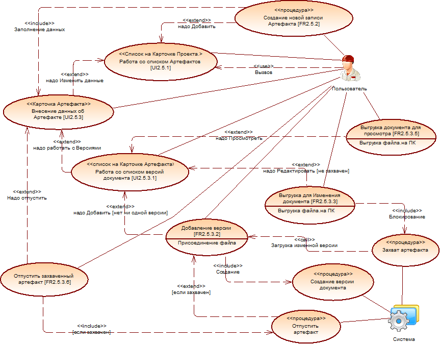
Figure 4. - Uses of Artifact control
To combat the complexity and benefit of the convenience of managing requirements, it is necessary to provide for their division into types. For example:
And since we have broken them into parts, it makes sense; in addition, each segment is additionally endowed with its own specific attributes.
This is the minimum set that allows you to simulate the entity "Requirement". Perhaps in the course of further consideration, we will expand it.
Having dealt with the Requirements, we proceed to the next step - processing the Specifications. The specifications themselves in the system appear during the design process, based on the requirement. It is not superfluous to note that they arise, just as a result of the fulfillment of tasks connected by this very requirement. For example, a task might sound like this: “Develop a requirement specification”. At the same time, it is even possible to link the “Report on the implementation” of this task with its solution - the “Specification”, which was revealed to the world as a result of execution.
Such specifications, unlike requirements, should take into account specific tools, platforms, practices that programmers will use in the project, and therefore Team Lead, Solution architects or Software Engineering Manager take the most direct part in their formation. Accordingly, it is their preferences that should be taken into account in this context.
In fact, the specification translates user requirements to the developer level, normalizing them, detailing, leading to the concepts with which programmers operate: Forms, Tables, Buttons, Procedures, etc.
A possible data model is presented in Fig.5.
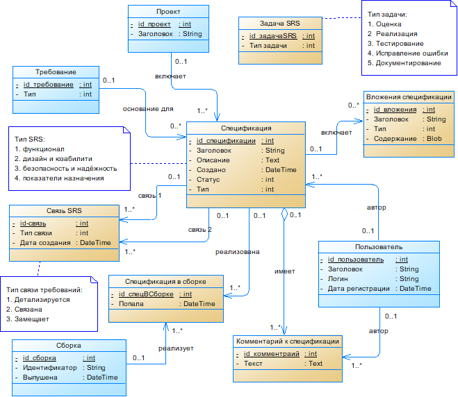
Figure 5. - Model of organization of tasks by specification
In contrast to the requirement that can be repeated from project to project, the specification is very unique for each implementation, in each case. After all, this is the embodiment of the requirements in certain conditions, a specific IT project. Therefore, the “Project” attribute has been added to the specification, within which this embodiment takes place. Also link her reference to the "Requirement."
The connection between specifications is arranged in the same way as it was organized in the requirements.
Like the requirements, the specification is provided with the possibility of discussion, through comments and a chance to attach attachment files to it.
For convenience, the specifications are also divided into types. For example:
And the types of tasks will be expanded accordingly in comparison with tasks for requirements:
Let us once again focus on determining the place of specification in the general software production chain. On the one hand, we established a link with the requirement, which was the reason for the appearance of the specification. On the other hand, as a consequent, we will tie up the product assembly in which this specification is implemented. And since the implementation of the same specification can appear in different assemblies, we connect them not directly, but through the “many-to-many” isolation - the “Specification in the assembly”.
Now you can track, not only those specifications that need to be tested in the new assembly, but also, for example, in which assemblies the specification solutions appeared, but also in which versions of the product the requirement was implemented, etc.
For good, the specifications themselves should differ among themselves, depending on the area of their application, at least by a set of attributes. For example, templates for describing forms, reports, procedures, access matrices, etc. I can vary considerably in composition. Also used platforms, libraries, services and other tools can have a great impact on this affinity.
When the functionality of the target product is implemented in the code, it should somehow add up to some intangible asset, the work of which can be used in some way. For example, to begin with - to test.
Thus, having implemented a certain set of specifications, for example, selected for iteration, the team needs to assemble the product, which will receive its unique version and can be transferred to the next stage of production.
Introduce the “Build” entity into the model. A possible data model is presented in Figure 6.
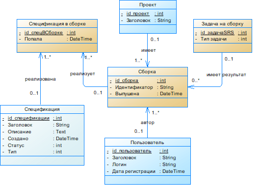
Figure 6. - Model organization assemblies
Each build is performed for a specific project and in the model has a link to it. About the organization of specifications in the assembly, we have already spoken in the previous section.
The tasks set for the assembly object can have the following types:
According to the reports to the tasks, we can determine at what sites, when and by whom each particular assembly was deployed.
If you need to start a new development cycle, or to correct an error, or to eliminate inaccuracies, you can create new tasks on the specification. It is easy to determine in which assembly its latest version was implemented.
As a result of the completed design, questions and inconsistencies almost inevitably arose.
Chicken and egg dilemma. It turns out a new "requirement" can be created on the basis of the "task on demand", another and already existing. For example, if it is necessary to detail it, we directly create a task from this requirement: “Detail the current requirement”. As a result of its execution, the following chain is formed: first, this task itself is created on the basis of a requirement. Secondly, according to the task, in fulfillment of its own, a new requirement is created. Further, similarly, a “specification” is born through a task on demand.
And here a reasonable question arises: should there have been the very first requirement somewhere, how was it created without a task? Well, even if it turns out that “it was possible”, how should we mark the work on creating the “number one” requirement? Get out here of course possible. For example, to create a requirement without any grounds (in the system), and after that, hang on it a task in which to write off the time for its creation, processing, etc.
Slightly less noticeable is the problem in solving the build creation. After all, it is also registered in the system before the creation of the first “assembly task”. And it is needed at least in order to attach new implementations of specifications to the assembly (or rather, its project). But in this case, you can organize, for example, the work of the service, which upon command will register a new assembly in the system, assign a version number to it, etc. As if the work itself for the employee there, and the assembly here it is already in the system. And the time to write off seems to be nothing. Also get out.
And further. In multilayer projects, it is often necessary to divide the product into interacting modules, services, and other integrations. In this case, the product itself has to be assembled from a multitude of assemblies, as if smaller products. And they are not necessarily all released simultaneously in a crowd. Some product is still relevant, and some may have to be reassembled anew. Accordingly, it is necessary to establish the compatibility (or portability) of the subsystems with each other and the recommended assemblies of assemblies. But let's return to this issue later when we consider the design work in the software production process. see "Part 3"
I Introduction
II Market Analysis Solutions
1. Standardization of system functions on the market
2. Disadvantages of existing systems
3. Challenges in creating a support system for the production of information systems
III Designing the basic structure of the system
1. The division of problems to be solved by type
2. Requirements and tasks for them
First, focus on the problem, how work can be organized regarding the requirements for the product being created. Its performers and authors are most likely somehow tied to the functions of collecting and analyzing information. People are not ordinary and a little conservative, and we will adapt to them.
A possible data model is presented in Fig.3.
')
Figure 3. - Model of the organization of tasks on demand
The requirements themselves are inherently very changeable, and their authors are often capricious. To combat this challenge, we will move most of the “Requirements” properties into a separate class - “Requirements Content”. By actually separating the frequently changing details from conditionally permanent, we will be able to store and view the entire evolution of the formation of the context of the requirement, without affecting the other stationary details. In order to understand what set of "Requirements Contents" is currently relevant (one of the entire set), you can use the reverse link to the "Requirements" table, as shown in Fig.3. Opponents of the use of backlinks can organize a weak link indicating the actual version of the content (just a string) in the request, or, for example, keep the date / time of the creation of the actual content. In general, as you like.
The next moment, the requirements most often arise in the framework of a project. But it may be that the plan, or most of it, is suitable for both one project and another and it is simply not advisable to duplicate requirements. Therefore, we associate the requirement with the project, through a bundle of many to many: “The requirement in the project”. Well, of course the status of the requirements in different projects may be different. For example, in one project it has long been implemented, and in another it is still being discussed. Therefore, we will close the status not on the “Requirement” itself, but on the link “Requirement in the project”.
In order not to cut the wings of the fantasy of the users of the system, while logically linking the requirements themselves to each other, we will link them with multiple references. Thus, we will provide an opportunity to coordinate two requirements not with one, but with a multitude of links characterizing different sides of interactivity. But the hierarchical subordination of the requirements, however, we leave aside. This view is still familiar. After all, navigation in the tree structure, which details downwards and abstracts upwards, is easier perceived than wandering in the web of a graph.
Of course, the "Requirement" should be provided with the possibility of discussion, through comments. For those who have a non-trivial discussion and agreement rules, you can look at the plots from the workflow and take a more complex business process as a basis.
It should also be possible to attach attachment files to the request, and it would be nice to divide them by type. In general, it is precisely for requirements that it is interesting to organize attachments in the form of accounting for artifacts, supporting them with versioning, typing a view, “capturing” for recording, etc.
Found in my archive of requirements, suitable UseCase for working with artifacts. I will bring it on fig. 4, unchanged as it was fixed.
Figure 4. - Uses of Artifact control
To combat the complexity and benefit of the convenience of managing requirements, it is necessary to provide for their division into types. For example:
- Architecture;
- Functionality;
- Business processes;
- Design and usability;
- Safety and reliability;
- Destination indicators;
- Documenting;
And since we have broken them into parts, it makes sense; in addition, each segment is additionally endowed with its own specific attributes.
This is the minimum set that allows you to simulate the entity "Requirement". Perhaps in the course of further consideration, we will expand it.
3. Specifications and tasks for them
Having dealt with the Requirements, we proceed to the next step - processing the Specifications. The specifications themselves in the system appear during the design process, based on the requirement. It is not superfluous to note that they arise, just as a result of the fulfillment of tasks connected by this very requirement. For example, a task might sound like this: “Develop a requirement specification”. At the same time, it is even possible to link the “Report on the implementation” of this task with its solution - the “Specification”, which was revealed to the world as a result of execution.
Such specifications, unlike requirements, should take into account specific tools, platforms, practices that programmers will use in the project, and therefore Team Lead, Solution architects or Software Engineering Manager take the most direct part in their formation. Accordingly, it is their preferences that should be taken into account in this context.
In fact, the specification translates user requirements to the developer level, normalizing them, detailing, leading to the concepts with which programmers operate: Forms, Tables, Buttons, Procedures, etc.
A possible data model is presented in Fig.5.
Figure 5. - Model of organization of tasks by specification
In contrast to the requirement that can be repeated from project to project, the specification is very unique for each implementation, in each case. After all, this is the embodiment of the requirements in certain conditions, a specific IT project. Therefore, the “Project” attribute has been added to the specification, within which this embodiment takes place. Also link her reference to the "Requirement."
The connection between specifications is arranged in the same way as it was organized in the requirements.
Like the requirements, the specification is provided with the possibility of discussion, through comments and a chance to attach attachment files to it.
For convenience, the specifications are also divided into types. For example:
- Functional;
- Design and usability;
- Safety and reliability;
- Destination indicators;
And the types of tasks will be expanded accordingly in comparison with tasks for requirements:
- Evaluation;
- Implementation;
- Testing;
- Error correction;
- Documenting;
Let us once again focus on determining the place of specification in the general software production chain. On the one hand, we established a link with the requirement, which was the reason for the appearance of the specification. On the other hand, as a consequent, we will tie up the product assembly in which this specification is implemented. And since the implementation of the same specification can appear in different assemblies, we connect them not directly, but through the “many-to-many” isolation - the “Specification in the assembly”.
Now you can track, not only those specifications that need to be tested in the new assembly, but also, for example, in which assemblies the specification solutions appeared, but also in which versions of the product the requirement was implemented, etc.
For good, the specifications themselves should differ among themselves, depending on the area of their application, at least by a set of attributes. For example, templates for describing forms, reports, procedures, access matrices, etc. I can vary considerably in composition. Also used platforms, libraries, services and other tools can have a great impact on this affinity.
4. Assemblies and tasks for them
When the functionality of the target product is implemented in the code, it should somehow add up to some intangible asset, the work of which can be used in some way. For example, to begin with - to test.
Thus, having implemented a certain set of specifications, for example, selected for iteration, the team needs to assemble the product, which will receive its unique version and can be transferred to the next stage of production.
Introduce the “Build” entity into the model. A possible data model is presented in Figure 6.
Figure 6. - Model organization assemblies
Each build is performed for a specific project and in the model has a link to it. About the organization of specifications in the assembly, we have already spoken in the previous section.
The tasks set for the assembly object can have the following types:
- assembly release;
- integration testing assembly;
- installation of the assembly on the stand;
According to the reports to the tasks, we can determine at what sites, when and by whom each particular assembly was deployed.
If you need to start a new development cycle, or to correct an error, or to eliminate inaccuracies, you can create new tasks on the specification. It is easy to determine in which assembly its latest version was implemented.
5. Analysis of the current design phase
As a result of the completed design, questions and inconsistencies almost inevitably arose.
Chicken and egg dilemma. It turns out a new "requirement" can be created on the basis of the "task on demand", another and already existing. For example, if it is necessary to detail it, we directly create a task from this requirement: “Detail the current requirement”. As a result of its execution, the following chain is formed: first, this task itself is created on the basis of a requirement. Secondly, according to the task, in fulfillment of its own, a new requirement is created. Further, similarly, a “specification” is born through a task on demand.
And here a reasonable question arises: should there have been the very first requirement somewhere, how was it created without a task? Well, even if it turns out that “it was possible”, how should we mark the work on creating the “number one” requirement? Get out here of course possible. For example, to create a requirement without any grounds (in the system), and after that, hang on it a task in which to write off the time for its creation, processing, etc.
Slightly less noticeable is the problem in solving the build creation. After all, it is also registered in the system before the creation of the first “assembly task”. And it is needed at least in order to attach new implementations of specifications to the assembly (or rather, its project). But in this case, you can organize, for example, the work of the service, which upon command will register a new assembly in the system, assign a version number to it, etc. As if the work itself for the employee there, and the assembly here it is already in the system. And the time to write off seems to be nothing. Also get out.
And further. In multilayer projects, it is often necessary to divide the product into interacting modules, services, and other integrations. In this case, the product itself has to be assembled from a multitude of assemblies, as if smaller products. And they are not necessarily all released simultaneously in a crowd. Some product is still relevant, and some may have to be reassembled anew. Accordingly, it is necessary to establish the compatibility (or portability) of the subsystems with each other and the recommended assemblies of assemblies. But let's return to this issue later when we consider the design work in the software production process. see "Part 3"
Source: https://habr.com/ru/post/354258/
All Articles