Hall Effect Sensors for a Brushless Motor: Returning Quadrature Encoders
This is the third article on quadrature decoders, this time with application to the control of brushless motors.
Task: there is an ordinary Chinese brushless collector, you need to connect it to the Copley Controls 503 controller. Unlike the cheap copter controllers, the 503rd wants a signal from the hall sensors, which are not on the engine. Let's understand what sensors are needed for and how to install them.
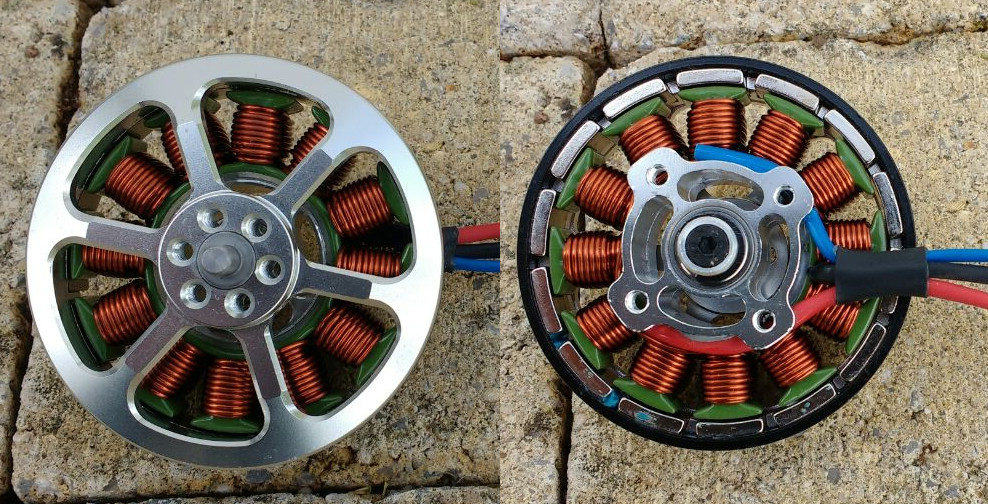
As an illustration, I will take a very common motor with twelve coils in the stator and fourteen magnets in the rotor. The options for winding and the number of coils / magnets are quite a few, but the essence always remains the same. Here is a photo of my specimen from two sides; both the coils and the magnets in the rotor are perfectly visible:
')
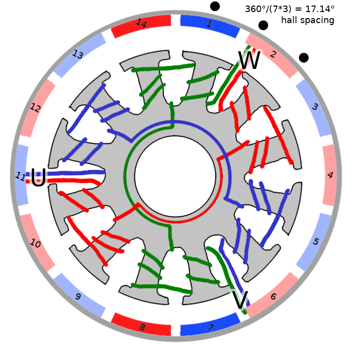
To make it even clearer, I drew his scheme, the poles of the rotor magnets are marked in color, red for the north and blue for the south:
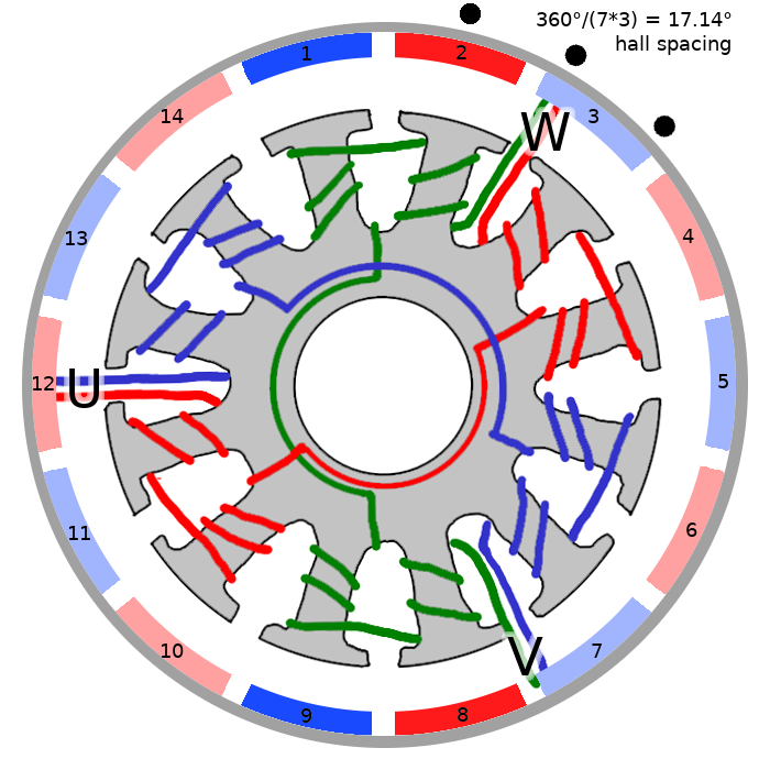
Do not pay attention to the hall sensors yet, they are not there anyway :)
What happens if you give a plus to pin V, and a minus to pin W (output U is not connected to anything)? Obviously, the current will flow in coils wound with a green wire. The coils are wound in a different direction, so the top two coils will be attracted to magnets 1 and 2, and the bottom two to magnets 8 and 9. The remaining coils and magnets practically do not play a role in this configuration, so I selected exactly magnets 1,2,8 and 9. With such a powering of the motor, it obviously will not spin, and will have seven stable rotor positions evenly distributed around the entire circumference (the left upper green stator coil can attract magnets 1, 3, 5, 7, 9, 11, 13).
Let's write down our actions in this tablet:
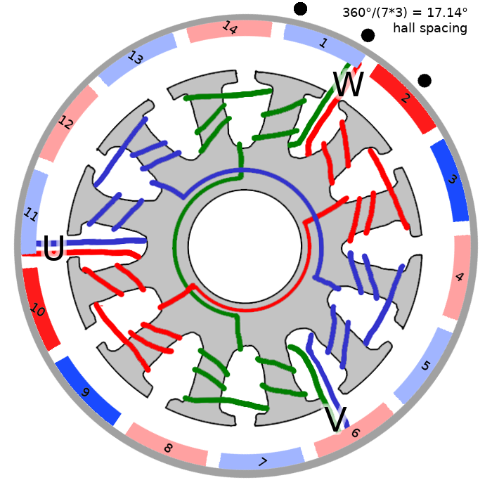
And what will happen if now apply plus for U and minus for W? The red coils draw magnets 3, 4, 10 and 11 to themselves, thus slightly turning the rotor (I still highlight the magnets for which the rotor pulls):
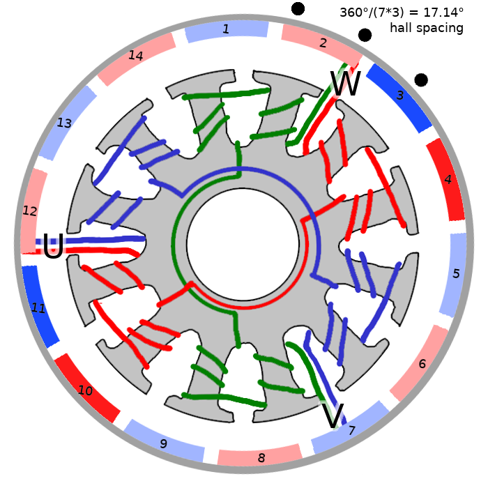
Let's calculate how much the rotor turns: between the slits of the magnets 1-2 and 3-4 we have 51.43 ° (= 360 ° * 2/7), and between the corresponding slits in the stator 60 ° (= 360 ° / 12 * 2). Thus, the rotor will turn to 8.57 °. Let's update our tablet:
Now God himself ordered to give + to U and - to V!
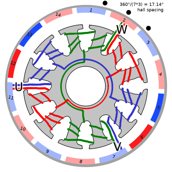
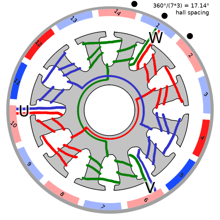
Now it's time to align the magnets with the green coils, so we apply voltage to them, but the red and blue magnets are reversed, so now we need to apply reverse voltage:
With the remaining two configurations everything is exactly the same:
If we repeat the very first step again, our rotor will rotate exactly one seventh turn. So, our motor has three outputs in total, we can apply voltage to two of them in six different ways 6 = 2 * C 2 3 , and we have already sorted them all out. If the supply voltage is not chaotic, but in a strict order, which depends on the position of the rotor, the engine will rotate.
We write again the whole sequence for our engine:
There is one caveat: for a conventional collector motor, brushes are responsible for switching windings, and here we need to determine the position of the rotor ourselves.
Now let's put the three hall sensors in the black points indicated in the diagram. Let's agree that the sensor produces a logical unit when it is opposite a red magnet. In total there are six (surprise!) Possible states of three sensors: 2 3 - 2. There are 8 possible states in total, but due to the distance between the sensors, they cannot all three be in a logical zero or in a logical one:

Notice that they generate three signals that are 1/3 periods off each other. By the way, electricians use the word degrees, talking about 120 °, which finally confuses noobs like me. If we want to make our own motor controller, then it is enough to read the signal from the sensors, and accordingly switch the voltage on the windings.
To accommodate the sensors, I used just this scarf, the design of which I took here . The link is the eagle project, so I just ordered many similar handkerchiefs from the Chinese right away:
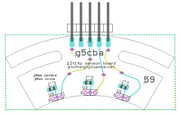
These scarves carry only three hall sensors, nothing else. Well, to taste you can put capacitors, I did not bother. Very conveniently made long slots for adjusting the position of the sensors relative to the stator.
Still would! The only difference is that incremental encoders give two signals that are shifted relative to each other by 90 °, and we have three signals that are shifted by 120 °. What happens if you start any two of them on a regular quadrature decoder, for example, the same blue tablet ? We will be able to determine the position of the shaft with an accuracy of four counts on one seventh turn, or 28 counts per turn. If you do not understand what I mean, read the principle of operation of the quadrature decoder in the first article.
I thought for a long time, how can I use all three signals, because we have six events on one seventh turn, we should be able to get 42 readings per revolution. In the end, I decided to go for brute force, since the blue tablet has a bunch of hardware quadrature decoders, so I decided to start three counters in it:
It can be seen that at each event we have two of them increase, therefore adding three counters, and dividing by two, we get a uniformly ticking shaft position determinant, with an accuracy of 6 * 7 = 42 counts per revolution!
This is how the layout of connecting Hall sensors to a blue tablet looks like:
In some applications (for example, for copters) all these troubles are not needed. The controllers try to guess what is happening with the rotor by the current in the coils. On the one hand, this is less of a problem, but on the other hand, sometimes it leads to problems with the moment the engine starts, so it is hardly applicable, for example, in robotics, where near-zero speeds are needed. Let's try to power our engine from the usual Chinese ESC (electronic speed controller) copter.
My controller wants a PPM signal at the input: it is a pulse with a frequency of 50 Hz, the pulse length sets the speed: 1ms - stop, 2ms - maximum possible speed (counted as engine KV * voltage).
Here I posted the source code and the Cuban files for the blue tablet. Timer 1 generates PWM for ESC, timers 2,3,4 count corresponding quadrature signals. Since in the last article I described in great detail where and what to click, here I only give a link to the source code.
At my ESC input, I give a sawtooth speed task, let's see how it performs. The output of the blue pill is here , and the code that draws the graph is here .
Since my engine has a nominal 400KV, and the power I gave 10V, then the maximum speed should be around 4000 rpm = 419 rad / s. Well, here's the schedule arrived:
It can be seen that the real momentum corresponds to the task very approximately, which is tolerable for copters, but is completely inapplicable in many other situations, why, in fact, I want to use more advanced controllers that need signals from the hall sensors. Well, the bonus, I get the angle of rotation of the rotor, which is extremely useful.
I spent my childhood hugging this book, but it was just now that I had a chance to smoke the principles of the work of beskleklectorny.
It turns out that stepper motors and here such kopternye motors are (conceptually) one and the same. The difference is only in the number of phases: the shagoviki (usually, there are exceptions) are controlled by two phases shifted by 90 °, and the beskollektotelniki (again, usually) by three phases shifted by 120 °.
Of course, there are other, purely practical differences: shagoviki designed to increase holding moment and repeatability of steps, while Copter engines for the speed and smoothness of rotation, which affects the number of windings, bearings, etc. But in the end, the usual besklelektornik can be used in stepping mode, and step in a constant rotation, they will have the same control.
Update: beautiful animation from Arastas :
- Article one: the principle of the quadrature decoder + code for arduino.
- Article two: quadrature decoder on stm32.
Task: there is an ordinary Chinese brushless collector, you need to connect it to the Copley Controls 503 controller. Unlike the cheap copter controllers, the 503rd wants a signal from the hall sensors, which are not on the engine. Let's understand what sensors are needed for and how to install them.
Likbez: the principle of operation of the brushless motor
As an illustration, I will take a very common motor with twelve coils in the stator and fourteen magnets in the rotor. The options for winding and the number of coils / magnets are quite a few, but the essence always remains the same. Here is a photo of my specimen from two sides; both the coils and the magnets in the rotor are perfectly visible:
')
To make it even clearer, I drew his scheme, the poles of the rotor magnets are marked in color, red for the north and blue for the south:
Do not pay attention to the hall sensors yet, they are not there anyway :)
What happens if you give a plus to pin V, and a minus to pin W (output U is not connected to anything)? Obviously, the current will flow in coils wound with a green wire. The coils are wound in a different direction, so the top two coils will be attracted to magnets 1 and 2, and the bottom two to magnets 8 and 9. The remaining coils and magnets practically do not play a role in this configuration, so I selected exactly magnets 1,2,8 and 9. With such a powering of the motor, it obviously will not spin, and will have seven stable rotor positions evenly distributed around the entire circumference (the left upper green stator coil can attract magnets 1, 3, 5, 7, 9, 11, 13).
Let's write down our actions in this tablet:
| Rotor rotation angle | U | V | W |
| 0 ° | nc | + | - |
And what will happen if now apply plus for U and minus for W? The red coils draw magnets 3, 4, 10 and 11 to themselves, thus slightly turning the rotor (I still highlight the magnets for which the rotor pulls):
Let's calculate how much the rotor turns: between the slits of the magnets 1-2 and 3-4 we have 51.43 ° (= 360 ° * 2/7), and between the corresponding slits in the stator 60 ° (= 360 ° / 12 * 2). Thus, the rotor will turn to 8.57 °. Let's update our tablet:
| Rotor rotation angle | U | V | W |
| 8.57 ° | + | nc | - |
Now God himself ordered to give + to U and - to V!
| Rotor rotation angle | U | V | W |
| 17.14 ° | + | - | nc |
Now it's time to align the magnets with the green coils, so we apply voltage to them, but the red and blue magnets are reversed, so now we need to apply reverse voltage:
| Rotor rotation angle | U | V | W |
| 25.71 ° | nc | - | + |
With the remaining two configurations everything is exactly the same:
| Rotor rotation angle | U | V | W |
| 34.29 ° | - | nc | + |
| Rotor rotation angle | U | V | W |
| 42.85 ° | - | + | nc |
If we repeat the very first step again, our rotor will rotate exactly one seventh turn. So, our motor has three outputs in total, we can apply voltage to two of them in six different ways 6 = 2 * C 2 3 , and we have already sorted them all out. If the supply voltage is not chaotic, but in a strict order, which depends on the position of the rotor, the engine will rotate.
We write again the whole sequence for our engine:
| Rotor rotation angle | U | V | W |
| 0 ° | nc | + | - |
| 8.57 ° | + | nc | - |
| 17.14 ° | + | - | nc |
| 25.71 ° | nc | - | + |
| 34.29 ° | - | nc | + |
| 42.86 ° | - | + | nc |
There is one caveat: for a conventional collector motor, brushes are responsible for switching windings, and here we need to determine the position of the rotor ourselves.
Hall Sensors
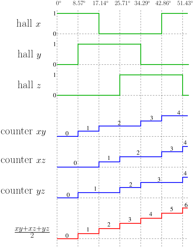
Now let's put the three hall sensors in the black points indicated in the diagram. Let's agree that the sensor produces a logical unit when it is opposite a red magnet. In total there are six (surprise!) Possible states of three sensors: 2 3 - 2. There are 8 possible states in total, but due to the distance between the sensors, they cannot all three be in a logical zero or in a logical one:
Notice that they generate three signals that are 1/3 periods off each other. By the way, electricians use the word degrees, talking about 120 °, which finally confuses noobs like me. If we want to make our own motor controller, then it is enough to read the signal from the sensors, and accordingly switch the voltage on the windings.
To accommodate the sensors, I used just this scarf, the design of which I took here . The link is the eagle project, so I just ordered many similar handkerchiefs from the Chinese right away:
These scarves carry only three hall sensors, nothing else. Well, to taste you can put capacitors, I did not bother. Very conveniently made long slots for adjusting the position of the sensors relative to the stator.
Wait, but this is very similar to the quadrature signal from a regular incremental encoder!
Still would! The only difference is that incremental encoders give two signals that are shifted relative to each other by 90 °, and we have three signals that are shifted by 120 °. What happens if you start any two of them on a regular quadrature decoder, for example, the same blue tablet ? We will be able to determine the position of the shaft with an accuracy of four counts on one seventh turn, or 28 counts per turn. If you do not understand what I mean, read the principle of operation of the quadrature decoder in the first article.
I thought for a long time, how can I use all three signals, because we have six events on one seventh turn, we should be able to get 42 readings per revolution. In the end, I decided to go for brute force, since the blue tablet has a bunch of hardware quadrature decoders, so I decided to start three counters in it:
It can be seen that at each event we have two of them increase, therefore adding three counters, and dividing by two, we get a uniformly ticking shaft position determinant, with an accuracy of 6 * 7 = 42 counts per revolution!
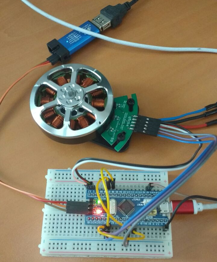
This is how the layout of connecting Hall sensors to a blue tablet looks like:
Why are there no sensors on the engine right away?
In some applications (for example, for copters) all these troubles are not needed. The controllers try to guess what is happening with the rotor by the current in the coils. On the one hand, this is less of a problem, but on the other hand, sometimes it leads to problems with the moment the engine starts, so it is hardly applicable, for example, in robotics, where near-zero speeds are needed. Let's try to power our engine from the usual Chinese ESC (electronic speed controller) copter.
My controller wants a PPM signal at the input: it is a pulse with a frequency of 50 Hz, the pulse length sets the speed: 1ms - stop, 2ms - maximum possible speed (counted as engine KV * voltage).
Here I posted the source code and the Cuban files for the blue tablet. Timer 1 generates PWM for ESC, timers 2,3,4 count corresponding quadrature signals. Since in the last article I described in great detail where and what to click, here I only give a link to the source code.
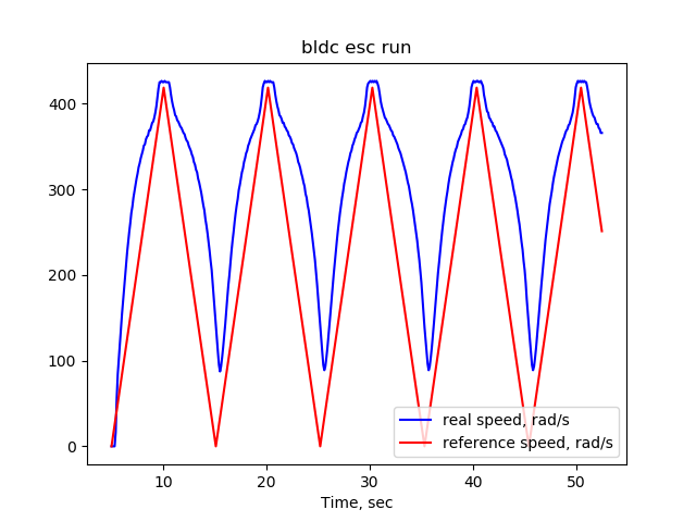
At my ESC input, I give a sawtooth speed task, let's see how it performs. The output of the blue pill is here , and the code that draws the graph is here .
Since my engine has a nominal 400KV, and the power I gave 10V, then the maximum speed should be around 4000 rpm = 419 rad / s. Well, here's the schedule arrived:
It can be seen that the real momentum corresponds to the task very approximately, which is tolerable for copters, but is completely inapplicable in many other situations, why, in fact, I want to use more advanced controllers that need signals from the hall sensors. Well, the bonus, I get the angle of rotation of the rotor, which is extremely useful.
Summarize
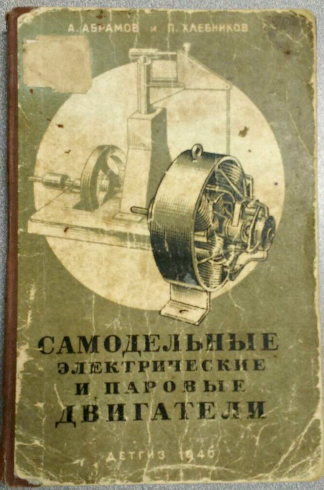
I spent my childhood hugging this book, but it was just now that I had a chance to smoke the principles of the work of beskleklectorny.
It turns out that stepper motors and here such kopternye motors are (conceptually) one and the same. The difference is only in the number of phases: the shagoviki (usually, there are exceptions) are controlled by two phases shifted by 90 °, and the beskollektotelniki (again, usually) by three phases shifted by 120 °.
Of course, there are other, purely practical differences: shagoviki designed to increase holding moment and repeatability of steps, while Copter engines for the speed and smoothness of rotation, which affects the number of windings, bearings, etc. But in the end, the usual besklelektornik can be used in stepping mode, and step in a constant rotation, they will have the same control.
Update: beautiful animation from Arastas :
Source: https://habr.com/ru/post/354086/
All Articles