Learn OpenGL. Lesson 5.3 - Shadow Maps

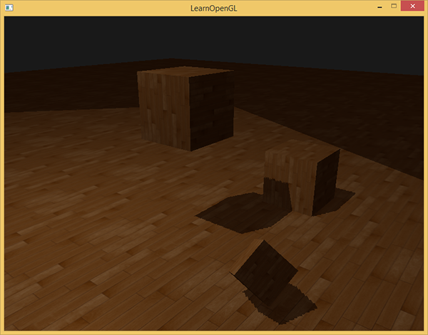
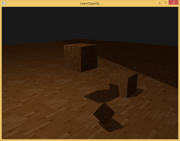
Shadow is the absence of light. If the rays from the light source do not fall on the object, as they are absorbed by another object, then the first object is in the shade. Shadows add realism to the image and let you see the relative position of objects. Thanks to him, the scene gets "depth." Compare the following scene images with and without shadows:
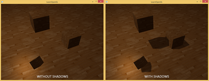
As you can see, the shadows make it much more obvious how objects are located relative to each other. Thanks to the shadows you can see that one of the cubes hangs in the air.
Shadows are difficult to implement, especially because the realtime algorithm for perfect shadows has not yet been invented. There are several good ways to approximate shadows, but they all have their own characteristics that need to be taken into account.
One of the methods, shadow maps, is relatively simple to implement, is used in most video games and gives decent results. Shadow maps are not so difficult to understand, they are quite cheap in terms of performance and easy to upgrade to more advanced algorithms (such as shadows from a point source of light or cascading shadow maps)
Part 1. Start
- Opengl
- Creating a window
- Hello window
- Hello triangle
- Shaders
- Textures
- Transformations
- Coordinate systems
- Camera
Part 2. Basic lighting
Part 3. Loading 3D Models
')
Part 4. OpenGL advanced features
- Depth test
- Stencil test
- Mixing colors
- Face clipping
- Frame buffer
- Cubic cards
- Advanced data handling
- Advanced GLSL
- Geometric shader
- Instancing
- Smoothing
Part 5. Advanced Lighting
(Translator's note - in the future, some Russian versions of the terms will be duplicated by the well-established English version. If you know them - there will be no misconceptions, you do not know - memorize together with the original term, there are a lot of good articles on the Internet in English and quite a few in Russian)
Shadow maps
The idea behind the shadow map is quite simple: we draw the scene from the point of view of the light source. Everything that we see is lit, the rest is in the shade. Imagine a piece of floor with a large cube between it and the light source. Since the light source "sees" a cube, rather than a piece of floor, this part of the floor will be shaded.

In the picture above, blue lines draw surfaces that the light source can see. Closed surfaces are painted black - they will be painted shaded. If you draw a line (ray) from a light source at the top of the rightmost cube, it will first cross the cube hanging in the air. Because of this, the left surface of the hanging cube is lit, unlike the cube on the right.
We want to find the point of the very first intersection of the ray with the surface and compare it with the other intersections. If the point of intersection of the ray with the surface does not coincide with the nearest intersection, then it is in the shadow. The repetition of such an operation for thousands of different rays from the source will be extremely inefficient and not suitable for drawing in each frame of the game.
Perhaps you have already read about the depth test: the Habré translation , the original . The value in the depth buffer is the fragment depth from the camera point of view, limited to values from 0 to 1. What if we render the scene from the point of view of the light source and store the depth values in the texture? In this way, we get the smallest depth values that can be seen from the point of view of the light source. In addition, the depth values show the surface closest to the light source. Such a texture is called a depth map (depth map) or a shadow map (shadow map) .

The left picture shows a directional light source (all rays are parallel), casting a shadow on the surface below the cube. Using the depth values stored in the texture, we find the surface closest to the source and with its help we determine what is in the shadow. We create a depth map by rendering the scene as the view and projection matrices using the matrices corresponding to our light source.
Directional light with parallel rays has no position and is, as it were, "infinitely far." However, in order to create a shadow map, we will have to draw a scene from a position in the direction of light.
Note translator - openGL cuts off surfaces that are too far away (z> 1) or too close (z <0 or z <-1 depending on the settings)). The camera matrix is chosen so that the z coordinate for objects on the scene is in this interval, otherwise we will not see them. From a mathematical point of view, there is no position, but in reality the position of the camera can be considered a point that when drawn is displayed at the closest point in the center of the screen
In the picture on the right, we see the same light, the cube and the observer. We draw a fragment of the surface at point P , and we need to determine if it is in the shadow. To do this, we translate P into the coordinate space of the light source T(P) . Since the point P not visible from the point of view of light, its z coordinate in our example will be 0.9 . According to the coordinates of point x, we can look at the depth map and find out that the point closest to the light source is with a depth of 0.4. This value is smaller than for point P , therefore point P is in the shade.
Drawing shadows consists of two passes: first we draw a depth map, in the second pass we draw the world as usual, using the depth map to determine which parts of the surface are in the shadow. This may seem complicated, but when we go through everything step by step, everything will become clear.
Depth map
In the first pass, we will generate a depth map. A depth map is a texture with depth values, rendered from the point of view of the light source. We will then use it to calculate the shadows. To save the rendered result to the texture, we need a frame buffer (framebuffer) : Habre translation , the original .
First, create a frame buffer to draw a depth map:
unsigned int depthMapFBO; glGenFramebuffers(1, &depthMapFBO); After we create a 2D texture to use as a depth buffer for the frame buffer.
const unsigned int SHADOW_WIDTH = 1024, SHADOW_HEIGHT = 1024; unsigned int depthMap; glGenTextures(1, &depthMap); glBindTexture(GL_TEXTURE_2D, depthMap); glTexImage2D(GL_TEXTURE_2D, 0, GL_DEPTH_COMPONENT, SHADOW_WIDTH, SHADOW_HEIGHT, 0, GL_DEPTH_COMPONENT, GL_FLOAT, NULL); glTexParameteri(GL_TEXTURE_2D, GL_TEXTURE_MIN_FILTER, GL_NEAREST); glTexParameteri(GL_TEXTURE_2D, GL_TEXTURE_MAG_FILTER, GL_NEAREST); glTexParameteri(GL_TEXTURE_2D, GL_TEXTURE_WRAP_S, GL_REPEAT); glTexParameteri(GL_TEXTURE_2D, GL_TEXTURE_WRAP_T, GL_REPEAT); Creating a depth map does not look complicated. Since we are only interested in the depth values (and not the colors r,g,b,a ), we specify the texture format GL_DEPTH_COMPONENT . Set the height and width of the texture 1024 * 1024 - this will be the size of the depth map.
Now we attach the depth texture to the frame buffer as the depth buffer.
glBindFramebuffer(GL_FRAMEBUFFER, depthMapFBO); glFramebufferTexture2D(GL_FRAMEBUFFER, GL_DEPTH_ATTACHMENT, GL_TEXTURE_2D, depthMap, 0); glDrawBuffer(GL_NONE); glReadBuffer(GL_NONE); glBindFramebuffer(GL_FRAMEBUFFER, 0); When we draw the scene from the point of view of the light source, we are only interested in the depth, the color buffer is not needed. The frame buffer will be incomplete without the color buffer, so we must explicitly indicate that we are not going to render the color. To do this, we set GL_NONE for glDrawBuffer and glReadBuffer .
Now we have a properly configured framebuffer, which writes the depth values to the texture, and we can render the depth map. The full implementation for both rendering passes looks like this:
// 1. glViewport(0, 0, SHADOW_WIDTH, SHADOW_HEIGHT); glBindFramebuffer(GL_FRAMEBUFFER, depthMapFBO); glClear(GL_DEPTH_BUFFER_BIT); ConfigureShaderAndMatrices(); RenderScene(); // 2. ( ) glBindFramebuffer(GL_FRAMEBUFFER, 0); glViewport(0, 0, SCR_WIDTH, SCR_HEIGHT); glClear(GL_COLOR_BUFFER_BIT | GL_DEPTH_BUFFER_BIT); ConfigureShaderAndMatrices(); glBindTexture(GL_TEXTURE_2D, depthMap); RenderScene(); This code does not contain some details, but it gives the general idea of shadow maps. Focusing on glViewport calls: usually the size of the depth map is different from the size of the screen (or the texture into which the final image is rendered). If you forget to change it, only a square piece with a screen size will be updated to the depth texture or (if the texture is smaller) some of the information on it will not be displayed (it will remain outside the edges).
Light source space
The only thing that is unknown in the code above is what does the ConfigureShaderAndMatrices() function do?
In the second pass, it works as usual - it sets the appropriate view and projection matrices for the camera and the model matrix for the objects. However, in the first pass we use other matrices for projection and appearance: for drawing the scene from the point of view of the light source.
We simulate a directional light source, so all rays of light are parallel. For this reason, we will use the orthographic projection matrix for the light source (there are no perespect distortions in it).
float near_plane = 1.0f, far_plane = 7.5f; glm::mat4 lightProjection = glm::ortho(-10.0f, 10.0f, -10.0f, 10.0f, near_plane, far_plane); This is an example of the orthographic projection matrix used in the demo for this article. Since the projection matrix determines the distance at which you will see objects (i.e., the video card will not cut off as too close or far), you should make sure that the size of the clipping region contains all the objects you want to display in the depth map.
To create a view matrix in which all objects will be visible from the point of view of the light source, we will use the unpopular function glm::lookAt , now the light source “looks” to the center of the scene.
glm::mat4 lightView = glm::lookAt(glm::vec3(-2.0f, 4.0f, -1.0f), glm::vec3( 0.0f, 0.0f, 0.0f), glm::vec3( 0.0f, 1.0f, 0.0f)); (Approx. Lane - the first vector is the location of the camera, the second is where it looks, the third is the direction of looking up)
The combination of these two matrices gives us a transformation matrix from the coordinates of the world to the coordinates in which the light source "sees" the world. This is exactly what we need for rendering a depth map.
glm::mat4 lightSpaceMatrix = lightProjection * lightView; The lightSpaceMatrix matrix is exactly what we designated above as T With this matrix, we can average the scene as usual, using it instead of the view and projection matrixes of a conventional camera. However, we are only interested in the depth values, and we want to maintain performance without making unnecessary calculations for unused color. Therefore, we will write the simplest possible shader for drawing only the depth map.
Rendering to a depth map
When we render a scene for a light source, we only need the coordinates of the vertices and nothing else. For such a simple shader (let's call it simpleDepthShader ), we write a vertex shader:
#version 330 core layout (location = 0) in vec3 aPos; uniform mat4 lightSpaceMatrix; uniform mat4 model; void main() { gl_Position = lightSpaceMatrix * model * vec4(aPos, 1.0); } For each model, this shader maps the vertices of the model into the light source space using lightSpaceMatrix .
Since we do not have a color buffer in the frame buffer for shadows, the fragment shader does not require any calculations, and we can leave it empty:
#version 330 core void main() { // gl_FragDepth = gl_FragCoord.z; } An empty fragmentary shader does nothing, and at the end of the shader we will get an updated depth buffer. We can uncomment this line of code, the actual depth will be calculated in any case.
Drawing to the depth buffer turns into the following code:
simpleDepthShader.use(); glUniformMatrix4fv(lightSpaceMatrixLocation, 1, GL_FALSE, glm::value_ptr(lightSpaceMatrix)); glViewport(0, 0, SHADOW_WIDTH, SHADOW_HEIGHT); glBindFramebuffer(GL_FRAMEBUFFER, depthMapFBO); glClear(GL_DEPTH_BUFFER_BIT); RenderScene(simpleDepthShader); glBindFramebuffer(GL_FRAMEBUFFER, 0); The RenderScene function accepts a shader, calls the functions needed to draw, and instances the matrix of the model if necessary.
As a result, we have a filled depth buffer, for each pixel containing the depth of the nearest fragment from the point of view of light. You can project this texture onto a screen-sized rectangle and display it. (similar to what was in the post-processing in the example with frame buffer. Habré translation , original .)
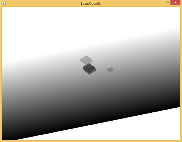
To draw a depth map on a rectangle, use the following shader:
#version 330 core out vec4 FragColor; in vec2 TexCoords; uniform sampler2D depthMap; void main() { float depthValue = texture(depthMap, TexCoords).r; FragColor = vec4(vec3(depthValue), 1.0); } If, when rendering the shadow, the projection matrix is perspective, not orthogonal, then the depth will vary nonlinearly. At the end of the article we will discuss this difference.
The source code for rendering the scene to a depth map can be seen here .
Drawing shadows
With the help of a properly made depth map, we can draw shadows. We check if the fragment is in the shadow with a fragment shader, but we are converting it to the light source space in the vertex shader.
#version 330 core layout (location = 0) in vec3 aPos; layout (location = 1) in vec3 aNormal; layout (location = 2) in vec2 aTexCoords; out VS_OUT { vec3 FragPos; vec3 Normal; vec2 TexCoords; vec4 FragPosLightSpace; } vs_out; uniform mat4 projection; uniform mat4 view; uniform mat4 model; uniform mat4 lightSpaceMatrix; void main() { vs_out.FragPos = vec3(model * vec4(aPos, 1.0)); vs_out.Normal = transpose(inverse(mat3(model))) * aNormal; vs_out.TexCoords = aTexCoords; vs_out.FragPosLightSpace = lightSpaceMatrix * vec4(vs_out.FragPos, 1.0); gl_Position = projection * view * model * vec4(aPos, 1.0); } From the new here - an additional vector FragPosLightSpace at the output of the vertex shader. We accept the same lightSpaceMatrix that was used in the first pass for drawing depth, and with its help we translate the vector into the space of the light source. The vertex shader transmits the vertices both in the current camera space ( vs_out.FragPos ) and in the light source space ( vs_out.FragPosLightSpace ) to the fragment simultaneously.
We will use a fragment shader based on the Blinna-Phong light model. In the fragment shader we will find the value of shadow - it will be equal to 1.0 if the fragment is in the shadow and 0.0 for the lit. The resulting diffuse and specular colors (diffuse and specular lighting) will be multiplied by (1.0 - shadow) . Shadows are rarely completely black due to indirect lighting, so background lighting will be present regardless of the shadow.
#version 330 core out vec4 FragColor; in VS_OUT { vec3 FragPos; vec3 Normal; vec2 TexCoords; vec4 FragPosLightSpace; } fs_in; uniform sampler2D diffuseTexture; uniform sampler2D shadowMap; uniform vec3 lightPos; uniform vec3 viewPos; float ShadowCalculation(vec4 fragPosLightSpace) { [...] } void main() { vec3 color = texture(diffuseTexture, fs_in.TexCoords).rgb; vec3 normal = normalize(fs_in.Normal); vec3 lightColor = vec3(1.0); // ambient vec3 ambient = 0.15 * color; // diffuse vec3 lightDir = normalize(lightPos - fs_in.FragPos); float diff = max(dot(lightDir, normal), 0.0); vec3 diffuse = diff * lightColor; // specular vec3 viewDir = normalize(viewPos - fs_in.FragPos); float spec = 0.0; vec3 halfwayDir = normalize(lightDir + viewDir); spec = pow(max(dot(normal, halfwayDir), 0.0), 64.0); vec3 specular = spec * lightColor; // calculate shadow float shadow = ShadowCalculation(fs_in.FragPosLightSpace); vec3 lighting = (ambient + (1.0 - shadow) * (diffuse + specular)) * color; FragColor = vec4(lighting, 1.0); } This is mostly a copy of the shader, which we used in the example with lighting: Habre , advanced lighting .
Only the shadow calculation is added here. The main part of the work is done by the ShadowCalculation function. At the end of the fragment shader, we multiply the contribution from the diffuse and specular reflection of light by (1.0 - shadow) - that is, depending on how strongly the fragment is not obscured. In addition, this input shader additionally assumes the position of the fragment in the light source space and the texture with depth values (which was rendered in the first pass).
To check whether the fragment is in the shadow, let us position the position in the space of the light source to the normalized coordinates. When we return the vertex position in gl_Position in the vertex shader, openGL automatically divides x,y,z by w so that the perspective works correctly. Since FragPosLightSpace not transmitted as gl_Position , we will have to do this division ourselves.
float ShadowCalculation(vec4 fragPosLightSpace) { // perform perspective divide vec3 projCoords = fragPosLightSpace.xyz / fragPosLightSpace.w; [...] } Get the position of the fragment in the light source space.
When using orthographic projection, the coordinate w=1.0 does not change and division by w becomes unnecessary. But division is necessary when using a perspective projection, and our code will work correctly for both cases.(Note of the lane - the division by w must be done exactly in the fragment shader. In this article, the first picture shows the difference between the linear and perspective interpolation for texture coordinates.)
Texture coordinates are in the interval [0,1], and the coordinates of visible fragments during rendering take values in [-1,1]. We give them to the interval [0,1]:
projCoords = projCoords * 0.5 + 0.5; According to these coordinates, we can see the depth value in the texture - this will be the depth of the object closest to the light source.
float closestDepth = texture(shadowMap, projCoords.xy).r; To get the depth of the current fragment, we simply take its z coordinate in the light source space.
`` `with
float currentDepth = projCoords.z;
```currentDepth``` ```closestDepth``` , . ```c float shadow = currentDepth > closestDepth ? 1.0 : 0.0; The entire code of the ShadowCalculation function is as follows:
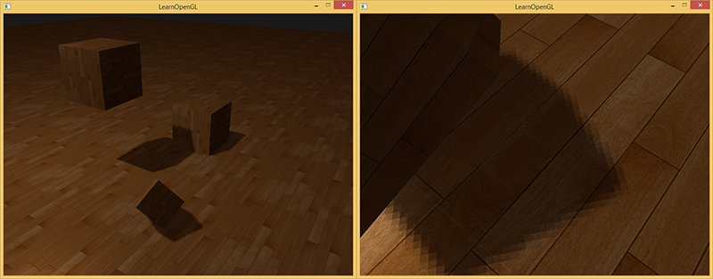
float ShadowCalculation(vec4 fragPosLightSpace) { // perform perspective divide vec3 projCoords = fragPosLightSpace.xyz / fragPosLightSpace.w; // transform to [0,1] range projCoords = projCoords * 0.5 + 0.5; // get closest depth value from light's perspective (using [0,1] range fragPosLight as coords) float closestDepth = texture(shadowMap, projCoords.xy).r; // get depth of current fragment from light's perspective float currentDepth = projCoords.z; // check whether current frag pos is in shadow float shadow = currentDepth > closestDepth ? 1.0 : 0.0; return shadow; } Using this shader together with textures and regular view and projection matrices for the second pass of the render will give the result approximately as in the picture:
If you did everything correctly, you will see shadows on the floor and dice (however, with some artifacts). Source code demo .
Improving shadow maps
We were able to achieve work for shadow maps, but you can see some artifacts in the image. The following text is devoted to their correction.
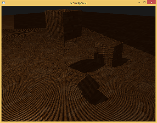
Moire pattern
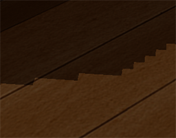
Obviously there is something wrong in the image below. The larger image resembles a moire pattern .

The entire floor is covered with clearly visible alternating black stripes. This effect can be explained with one karinka:

(Note. Trans. - to describe the effect, the author uses the term " shadow acne ". I could not find an established translation. I could translate this as "shadow points", but I still can’t find anything on the Russian-language Internet.)
Since the shadow map has a limited resolution (in the example above, we used a texture of 1024*1024 ), several pixels on the final image can get the same value from the depth map. The picture above shows the floor on which each slanting piece (from bottom to left up to right) is one texel from the depth map. (texel - texture pixel)
In general, this is normal, but it can be a problem if the light falls at an angle to the surface, as in the example above. Some fragments that receive depth from a texture get a value greater or less, which does not correspond to the real depth of the floor for this fragment. Because of this, some fragments are considered shaded - and we see stripes.
We can solve this problem with a small hack — a shift in depth values by a small amount (shadow bias) so that all the fragments are above the surface.
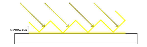
(Approx. Lane - I have a strong feeling that the pictures are not drawn correctly. In order for the fragment not to be obscured, the zigzag lines describing the values from the depth map must be below the surface)
float bias = 0.005; float shadow = currentDepth - bias > closestDepth ? 1.0 : 0.0; A shift of 0.005 for our scene as a whole solves the problem, but some surfaces that the light falls on at a very small angle will still have stripes of shadow. A more serious approach would be to change the shift depending on the angle at which the light falls on the surface. We use the scalar product.
float bias = max(0.05 * (1.0 - dot(normal, lightDir)), 0.005); Thus, floor-like surfaces that are almost perpendicular to the rays of light will have a very small shift. The greater the angle between the normal and the direction of the light, the greater the shift. The following picture shows the same scene, but using the shift: it looks clearly better.

The selection of the correct values for the shift requires their selection, since they may differ for each scene, but this is usually done by simply increasing the shift until the artifacts disappear.
Peter Pan Effect
(Piter Panning)
The disadvantage of using shear for depth is that we apply it to the actual depth of the object. As a result, this shift can become large enough so that there is a noticeable distance between the object and the shadow, which it casts as in the picture below (with an exaggeratedly large offset):

This is called the Peter Pan effect, since the shadow runs a little away from its object. We can use a little trick to solve most problems: use clipping of front-oriented polygons when drawing a depth map. Read about the facet on the Habré , the original .
By default, openGL cuts back oriented polygons. We can switch openGL to do the opposite.
In the first rendering pass, we need only the depth values, and it does not matter to us what depth to take - from the front or back surface. We will not notice the wrong results, since it doesn’t matter to us whether there are shadows inside the object - they are still not visible.

To remove the effect of Peter Pan, we cut off the frontal edges on the first pass. Note that you need to enable GL_CULL_FACE .
glCullFace(GL_FRONT); RenderSceneToDepthMap(); glCullFace(GL_BACK); // This solves the problem with the Peter Pen effect, but only for objects that have a surface on all sides. In our example, this works perfectly for cubes, but will not work for the floor, since cutting off the frontal polygons will completely remove the floor. If you are going to use this method, use cutting off fronted oriented polygons only where it makes sense.
(Note of the lane - specifically in this example, there is nothing to worry about cutting off the floor completely, as there are no objects below it, and it does not matter if there is a shadow under it or not.)
If objects are too close to the shaded surface, the result may look wrong. Use frontal clipping only for objects for which it makes sense. However, using well-chosen values for the shift, you can completely avoid the Peter Pen effect.
Another visible flaw that you might like or not is that some surfaces outside the scope of the light source can be painted shaded, even if theoretically the light should fall on them. This is due to the fact that for a remote point in the reference system of the light source, the coordinates will be greater than 1.0, and the texture coordinates will only vary from 0.0 to 1.0. If the surface is too far away from the light source, then there is no value for it in the depth map.
In the image above you can imagine a region of light - everything else is in the shadow. The lighted area shows how the depth map is projected onto the floor. The reason for this behavior is that earlier we set the GL_REPEAT mode for the depth texture.
1.0 — , ( ). "GL_CLAMP_TO_BORDER"
glTexParameteri(GL_TEXTURE_2D, GL_TEXTURE_WRAP_S, GL_CLAMP_TO_BORDER); glTexParameteri(GL_TEXTURE_2D, GL_TEXTURE_WRAP_T, GL_CLAMP_TO_BORDER); float borderColor[] = { 1.0f, 1.0f, 1.0f, 1.0f }; glTexParameterfv(GL_TEXTURE_2D, GL_TEXTURE_BORDER_COLOR, borderColor); , [0,1], 1.0, shadow 0.0. :
, . , . , .
z , 1.0, GL_CLAMP_TO_BORDER . ( 1.0) ( 1.0) — .
— , z .
float ShadowCalculation(vec4 fragPosLightSpace) { [...] if(projCoords.z > 1.0) shadow = 0.0; return shadow; } 1.0 .

, , , . , , .
PCF
Percentage-closer filtering
, , . , .
, . .
, .
() — PCF (Percentage-closer filtering), , . , — . , . .
PCF — :
float shadow = 0.0; vec2 texelSize = 1.0 / textureSize(shadowMap, 0); for(int x = -1; x <= 1; ++x) { for(int y = -1; y <= 1; ++y) { float pcfDepth = texture(shadowMap, projCoords.xy + vec2(x, y) * texelSize).r; shadow += currentDepth - bias > pcfDepth ? 1.0 : 0.0; } } shadow /= 9.0; textureSize — , . , , . , . 9 (x,y) , , .
/ texelSize , . PCF :
. , , (, 9 ). , PCF .
, PCF, . , .
vs
. , , . . .

( ). , — .
#version 330 core out vec4 FragColor; in vec2 TexCoords; uniform sampler2D depthMap; uniform float near_plane; uniform float far_plane; float LinearizeDepth(float depth) { float z = depth * 2.0 - 1.0; // Back to NDC return (2.0 * near_plane * far_plane) / (far_plane + near_plane - z * (far_plane - near_plane)); } void main() { float depthValue = texture(depthMap, TexCoords).r; FragColor = vec4(vec3(LinearizeDepth(depthValue) / far_plane), 1.0); // perspective // FragColor = vec4(vec3(depthValue), 1.0); // orthographic } , , . , . , .
:
- tutorial-16-shadow-mapping — .
- Shadow mapping — Part 1 : ogldev
- How shadow mapping works: — 3
- Common Techniques to Improve Shadow Depth Maps : Microsoft, .
Source: https://habr.com/ru/post/353956/
All Articles