Guide to create your own shaders in the Unreal Engine
Thanks to the node system, the material editor is a great tool for creating shaders. However, he has his limitations. For example, it is not possible to create loops and switch constructs there.
Fortunately, these limitations can be circumvented by writing your own code. To do this, there is a Custom node that allows you to write HLSL code.
In this tutorial you will learn the following:
')
- Create a custom node and customize its inputs
- Convert material nodes to HLSL
- Modify shader files with an external text editor.
- Create HLSL functions
To demonstrate all of these features, we will use HLSL to reduce the saturation of the scene image, display various scene textures and create a Gaussian blur (Gaussian blur).
Note: it is understood that you are already familiar with the basics of using the Unreal Engine. If you are new to the Unreal Engine, then learn our series of tutorials from ten parts of the Unreal Engine for beginners .
The tutorial also assumes that you are familiar with similar C languages, such as C ++ or C #. If you are familiar with syntactically similar languages, for example, Java, then you can also figure it out.
Note: this tutorial is part of a series of tutorials on shaders:
- Part 1: Cel Shading
- Part 2: Toon-contours
- Part 3: Creating your own shaders with HLSL
Getting Started
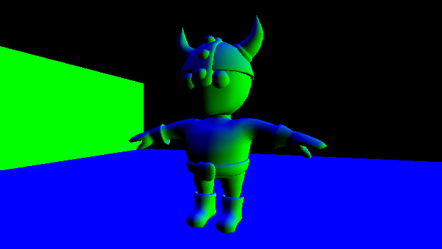
Start by downloading this tutorial (you can download it here ). Unzip them, go to CustomShadersStarter and open CustomShaders.uproject . You will see the following scene:
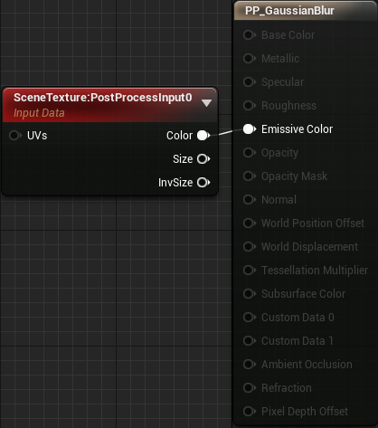
First we will use HLSL to reduce the saturation of the image of the scene. To do this, we need to create and apply a Custom node in the post-processing material.
Creating a custom node
Go to the Materials folder and open PP_Desaturate . We will edit this material to get a lower saturation effect.

First, create a custom node. Like other nodes, it can have several inputs, but only one output.

Then select the Custom node and go to the Details panel. You will see the following:

Here is what each of the properties do:
- Code: here we put our HLSL code
- Output Type: output can range from a single value ( CMOT Float 1 ) to a four- channel vector ( CMOT Float 4 ).
- Description: the text to be displayed on the node itself. This is a good way to name the custom nodes. Type Desaturate here.
- Inputs: here you can add and name input contacts. Then with the help of these names we will be able to refer to these entries in the code. Set input 0 to the name SceneTexture .

To reduce image saturation, replace the text inside the Code with the following:
return dot(SceneTexture, float3(0.3,0.59,0.11)); Note:dot()is a predefined function . Such features are built into the HLSL. If you need a function likeatan()orlerp(), then first check if there is already such a predefined function.
Finally, connect everything as follows:

Summarize:
- SceneTexture: PostProcessInput0 will output the color of the current pixel
- Desaturate will receive color and reduce its saturation. Then he displays the result in Emissive Color.
Click on Apply and close PP_Desaturate . Now the saturation of the image of the scene will be reduced.

You may be wondering where the saturation reduction code came from. When we use a material node, it is converted to HLSL. If you view the generated code, you can find the corresponding fragment and copy it. This is how I converted the Desaturation node to HLSL.
In the next section, we will learn how to convert a material node to HLSL.
Convert Material Nodes with HLSL
In this tutorial, we will convert to the HLSL SceneTexture node. This will come in handy later when we create a Gaussian blur.
To get started, go to the Maps folder and open GaussianBlur . Then go back to Materials and open PP_GaussianBlur .
Unreal generates HLSL for all nodes participating in the final output. In our case, Unreal will generate HLSL for the SceneTexture node.
To view the HLSL code of the entire material, select Window \ HLSL Code . This opens a separate window with the generated code.

Note: if the HLSL Code window is empty, you will need to enable it in the Live Preview Toolbar.

Since the generated code has a length of several thousand lines, it is quite difficult to navigate through it. To simplify the search, click on the Copy button and paste the code into a text editor (I use Notepad ++ ). Then close the HLSL Code window.
Now we need to find where the SceneTexture code is . The easiest way to do this is to find the definition for
CalcPixelMaterialInputs() . This is a function in which the engine calculates all the outputs of materials. If you look at the bottom of the function, you can see the final values for each output: PixelMaterialInputs.EmissiveColor = Local1; PixelMaterialInputs.Opacity = 1.00000000; PixelMaterialInputs.OpacityMask = 1.00000000; PixelMaterialInputs.BaseColor = MaterialFloat3(0.00000000,0.00000000,0.00000000); PixelMaterialInputs.Metallic = 0.00000000; PixelMaterialInputs.Specular = 0.50000000; PixelMaterialInputs.Roughness = 0.50000000; PixelMaterialInputs.Subsurface = 0; PixelMaterialInputs.AmbientOcclusion = 1.00000000; PixelMaterialInputs.Refraction = 0; PixelMaterialInputs.PixelDepthOffset = 0.00000000; Since this is a post-processing material, only EmissiveColor is important to us . As you can see, its value is the value of Local1 . Variables of the form LocalX are local variables that the function uses to store intermediate values. If you look just above the outputs, you can see how the engine calculates each local variable.
MaterialFloat4 Local0 = SceneTextureLookup(GetDefaultSceneTextureUV(Parameters, 14), 14, false); MaterialFloat3 Local1 = (Local0.rgba.rgb + Material.VectorExpressions[1].rgb); The finite local variable (in our case, Local1 ) is usually a “dummy” calculation, so it can be ignored. This means that the function for the SceneTexture node is the
SceneTextureLookup() function.Now that we have the desired function, let's test it.
Using the SceneTextureLookup function
To begin with, let us ask ourselves - what do the parameters do? Here is the
SceneTextureLookup() signature: float4 SceneTextureLookup(float2 UV, int SceneTextureIndex, bool Filtered) Here is what each parameter does:
- UV: the coordinate of the UV from which to sample. For example, UV with coordinates (0.5, 0.5) will sample the average pixel.
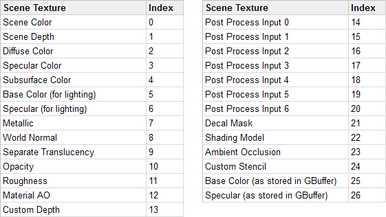
- SceneTextureIndex: determines from which texture of the scene to sample. Below is a table of each scene texture and its index. For example, for sampling Post Process Input 0 we will use index 14 .
- Filtered: determines whether bilinear filtering should be applied to the scene texture. Usually false .
For testing, we will display World Normal. Go to the material editor and create a Custom node called Gaussian Blur . Then paste the following into the Code field:
return SceneTextureLookup(GetDefaultSceneTextureUV(Parameters, 8), 8, false); So we will output World Normal to the current pixel.
GetDefaultSceneTextureUV() will get the UV of the current pixel.Note: prior to version 4.19, it was possible to obtain UV by passing TextureCoordinate as input. In 4.19, the correct way is to useGetDefaultSceneTextureUV()and pass in the desired index.
This is an example of how hand-written HLSL code may not be compatible with different versions of Unreal.
Next, unplug the SceneTexture node. Then attach a Gaussian Blur to Emissive Color and click on Apply .

At this point, you will get the following error:
[SM5] /Engine/Generated/Material.ush (1410,8-76): error X3004: undeclared identifier 'SceneTextureLookup'
She tells us that
SceneTextureLookup() does not exist in our material. Why does this work when using the SceneTexture node, but does not work with the Custom node? When using SceneTexture, the compiler includes the definition of SceneTextureLookup() in the code. Since we do not use this node, we cannot use the function.Fortunately, this problem is easy to solve. Select the same texture for the SceneTexture node from which we are sampling. In our case, you need to choose WorldNormal .
Then connect it with Gaussian Blur . Finally, we need to give the input contact a name that is different from None . In this tutorial we will select SceneTexture .

Note: at the time of this writing, there was a bug in the engine: if the scene textures are not the same, then the editor crashes. However, since this works, we can safely change the texture of the scene in the Custom node.
Now the compiler will include the definition of
SceneTextureLookup() .Click Apply and return to the main editor. Now you will see the normal of the world for each pixel.
For now, editing the code in the Custom node is quite convenient, because we work with small fragments. However, when our code begins to grow, it will be more difficult to maintain it.
To optimize the workflow, Unreal allows us to add external shader files. Because of this, we can write code in our own text editor, and then go back to Unreal for compilation.
Using external shader files
First we need to create the Shaders folder. Unreal will view this folder when you use the
#include directive in the Custom node.Open the project folder and create a new Shaders folder. The project folder should look like this:

Then go to the Shaders folder and create a new file. Call it Gaussian.usf . It will be our shader file.
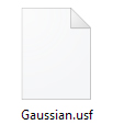
Note: Shader files must have a .usf or .ush extension .
Open Gaussian.usf in a text editor and paste the code shown below. After each change, save the file.
return SceneTextureLookup(GetDefaultSceneTextureUV(Parameters, 2), 2, false); This is the same code as before, but it displays Diffuse Color .
In order for Unreal to recognize the new folder and shaders, we need to restart the editor. After restarting, go to GaussianBlur . Then reopen PP_Gaussian Blur and replace the code in Gaussian Blur with the following:
#include "/Project/Gaussian.usf" return 1; Now after compilation the compiler will replace the first line with the contents of Gaussian.usf . Notice that we should not replace
Project name of our project.Click on Apply and return to the main editor. Now, instead of the normals of the world, you will see diffuse colors.

Now that everything is set up for convenient shader development, it is time to create a Gaussian blur (Gaussian blur).
Note: since this is not a Gaussian tutorial, I will not explain it in detail. If you want to know the details, then read the articles Gaussian Smoothing and Calculating Gaussian Kernels .
Create gaussian blur
As in the tutorial on toon-contours, this effect will use a convolution. The final output is the average of all pixels in the core.
With normal linear blur, all pixels have the same weight. With a wide blur this leads to artifacts. Gaussian blur avoids this by reducing the pixel weight when away from the center. This adds more importance to the center pixels.
When using material nodes, convolution is not ideal due to the large number of samples required. For example, with a 5 × 5 core, we need 25 samples. Double the size to 10 × 10, and the number of samples will increase to 100! At this point, the node graph will look like a plate of spaghetti.
And here the Custom node comes to the rescue. With it, we can write a small
for loop that samples each pixel in the core. The first step is to set the parameter that controls the radius of the sample.Creating a radius parameter
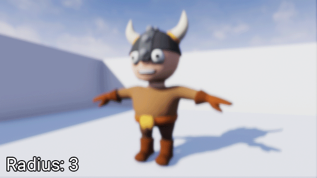
First back to the material editor and create a new ScalarParameter called Radius . Give it a default value of 1 .

The radius determines the level of image blur.
Next, create a new entry for Gaussian Blur and call it Radius . Then create a Round node and connect everything as follows:
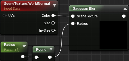
Round is necessary so that the kernel sizes are always integers.
Now it's time to start coding! Since for each pixel we need to calculate Gaussian blur twice (vertical and horizontal offsets), it would be logical to turn this into a function.
When using the Custom node, we cannot create functions in a standard way, because the compiler copies our code into a function. Since we cannot define functions inside a function, we get an error.
Fortunately, we can use this copy-and-paste to create global functions.
Creating global functions
As mentioned above, the compiler literally copies the text from the Custom node to the function. That is, if we have the following:
return 1; then the compiler will insert it into the CustomExpressionX function. He won't even indent!
MaterialFloat3 CustomExpression0(FMaterialPixelParameters Parameters) { return 1; } See what happens if we use this code:
return 1; } float MyGlobalVariable; int MyGlobalFunction(int x) { return x; The generated HLSL will turn into this:
MaterialFloat3 CustomExpression0(FMaterialPixelParameters Parameters) { return 1; } float MyGlobalVariable; int MyGlobalFunction(int x) { return x; } As you can see,
MyGlobalVariable and MyGlobalFunction() not inside the function. This makes them global, that is, we can use them anywhere.Note: Notice that there is no last bracket in the input code. This is important because the compiler inserts a bracket into the end. If we leave the bracket, as a result we will have two brackets and we get an error.
Now let's use this behavior to create a Gaussian function.
Creating a Gaussian function
The function for simplified Gaussians in one dimension looks like this:
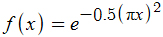
As a result, it gives a bell-shaped curve, which receives at the input values in the range from approximately -1 to 1. At the output, it gives a value from 0 to 1.
In this tutorial, we will place the Gaussian function in a separate Custom node. Create a new custom node and name it Global .
Then replace the Code text with the following:
return 1; } float Calculate1DGaussian(float x) { return exp(-0.5 * pow(3.141 * (x), 2)); Calculate1DGaussian() is a simplified 1D-Gaussian in code form.In order for this feature to be available, we need to use Global somewhere in the material column. The easiest way to do this is by multiplying Global by the first node of the graph. So we guarantee that global functions are defined before we use them in other Custom nodes.
To begin, set the Output Type Global node to CMOT Float 4 . We have to do this because we will multiply by SceneTexture of type float4 .

Next, create Multiply and connect everything as follows:

Click on Apply to compile. Now all subsequent Custom nodes will be able to use the functions defined in Global .
The next step is to use a
for loop to sample every pixel in the core.Multi-pixel sampling
Open Gaussian.usf and replace the code with the following:
static const int SceneTextureId = 14; float2 TexelSize = View.ViewSizeAndInvSize.zw; float2 UV = GetDefaultSceneTextureUV(Parameters, SceneTextureId); float3 PixelSum = float3(0, 0, 0); float WeightSum = 0; Here is what each variable is for:
- SceneTextureId: contains the index of the scene texture that we want to sample. Thanks to it, we are not obliged to rigidly set the index in function calls. In our case, the index is used for Post Process Input 0 .
- TexelSize: contains texel size. Used to convert offsets to UV space.
- UV: UV for the current pixel
- PixelSum: used to accumulate the color of each pixel in the core
- WeightSum: used to accumulate the weight of each pixel in the core
Next, we need to create two
for , one for vertical offsets, the other for horizontal ones. Add the following below the list of variables: for (int x = -Radius; x <= Radius; x++) { for (int y = -Radius; y <= Radius; y++) { } } So we will create a grid centered on the current pixel. Its dimensions are given as 2r + 1 . For example, if the radius is 2 , then the grid will have dimensions (2 * 2 + 1) by (2 * 2 + 1) or 5 × 5 .
Next we need to accumulate the colors and weights of the pixels. To do this, add the following code to the inner
for loop: float2 Offset = UV + float2(x, y) * TexelSize; float3 PixelColor = SceneTextureLookup(Offset, SceneTextureId, 0).rgb; float Weight = Calculate1DGaussian(x / Radius) * Calculate1DGaussian(y / Radius); PixelSum += PixelColor * Weight; WeightSum += Weight; Here is what each of the strings does:
- Calculates the relative offset of the sample pixel and converts it into UV space
- Based on the offset, it samples the scene texture (in our case, it is Post Process Input 0 )
- Calculates the weight of the sample pixel. To calculate 2D-Gaussians, it is sufficient to multiply two 1D-Gaussians. The division by
Radiusdone because the simplified Gaussian expects a value from -1 to 1 at the input. This division normalizesxandyin the desired interval. - Adds Weighted Color to
PixelSum - Adds weight to
WeightSum
Finally, we need to calculate the result, which is a weighted average. To do this, add the following to the end of the file (outside the
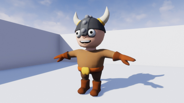
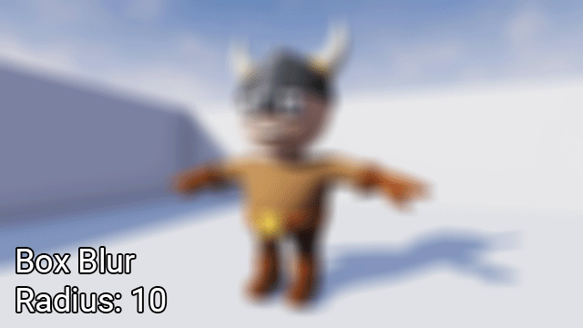
for loops): return PixelSum / WeightSum; And so we implemented a Gaussian blur! Close Gaussian.usf and go back to the material editor. Click on Apply and close PP_GaussianBlur . Use PPI_Blur to test different blur radii.
Note: sometimes the Apply button may be inactive. Just make a change that doesn't affect anything (for example, move the node), and it will become active again.
Restrictions
Despite the power of the Custom node, it has its drawbacks. In this section I will discuss some of the limitations and flaws in its use.
Rendering access
Custom nodes cannot access many parts of the rendering pipeline, such as lighting information and motion vectors. When using direct rendering, the situation is slightly different.
Version Compatibility Engine
HLSL code written in one version of Unreal will not necessarily work in another. As stated in the tutorial, up to version 4.19, we could use TextureCoordinate to get the UV texture of the scene. In version 4.19, you need to use
GetDefaultSceneTextureUV() for this.Optimization
Here is what Epic says about optimization:
The use of Custom nodes makes it impossible to minimize constants and can lead to a significantly larger number of instructions compared to a similar version built on nodes! The folding of constants is the optimization used by the UE4 to reduce the number of shader instructions if necessary.
For example, the chain of expressionsTime >Sin >Mul by parameter > Add -can and will be minimized by the UE4 engine in one instruction, the final Add. This is possible because all the inputs of this expression (Time, Parameter) are constants throughout the entire draw call, that is, they do not change for each pixel. UE4 cannot collapse anything in the Custom node, which can lead to the creation of less efficient shaders compared to similar versions based on ready-made nodes.
Therefore, it is best to use the Custom node only when it provides access to functionality that is not available in ready-made nodes.
Where to go next?
The finished project can be downloaded here .
If you want to get a deeper insight into the Custom node, then I recommend learning about Ryan Brooke’s blog . It has posts explaining in detail how to use the Custom node to create raymarching and other effects.
Source: https://habr.com/ru/post/353722/
All Articles