Unity3D animated spacecraft shield effect
Hi Habr! I want to tell how to make a shader for drawing a spacecraft shield in Unity3D.
The article is designed for beginners, but I will be glad if experienced shader writers will read and criticize the article.
Interested please under the cat. (Caution! Inside are heavy pictures and gifs).
The article is written as a set of instructions with explanations, even a complete beginner will be able to execute them and get a ready-made shader, but in order to understand what is happening, it is advisable to navigate in basic terms:
')
The effect consists of 3 main components:
Let us add these components to the shader in order, and by the end of the article we will get the effect as on the KDPV.
Let's start with the standard Unity3D shader:
Prepare it for our purposes.
We got a basic unlit translucent shader. Now it is necessary to make a shader from it, which uses the texture as a translucency mask and the color specified by the user as the pixel color:
You should have something like this:

While not very good, but this is the base on which the whole effect will be built.
In general, the Fresnel effect is the effect of increasing the intensity of the reflected beam with increasing its angle of incidence. But I use the formulas used in the calculation of this effect to set the dependence of the intensity of the glow of the shield on the viewing angle.
We start implementation using the approximate formula from cg tutorial on nvidia

where I is the direction from the camera to the top, N is the normal of the surface at the point of incidence
Done! After playing with the parameters of the Fresnel equation, you can get this picture

Now you can go to the most interesting - display hits on the shield.
I will describe just one of the possible response options to the hit; it is fairly simple and cheap in performance; it looks quite nice and, unlike the simplest ones, gives a nice picture when the hits are close.
Final result:
Exactly what is needed.
That's so easy and not too expensive, you can get quite a beautiful effect of the shield of the spacecraft.
I will outline the main directions of possible optimization:
Here is such
The article is designed for beginners, but I will be glad if experienced shader writers will read and criticize the article.
Interested please under the cat. (Caution! Inside are heavy pictures and gifs).
The article is written as a set of instructions with explanations, even a complete beginner will be able to execute them and get a ready-made shader, but in order to understand what is happening, it is advisable to navigate in basic terms:
')
- Shader
- Vertex shader
- Fragment / Pixel Shader
- UV coordinates
The effect consists of 3 main components:
- Base translucent shader using texture as transparency map and color as shield color
- Fresnel effect
- Shield Reaction
- Animation
Let us add these components to the shader in order, and by the end of the article we will get the effect as on the KDPV.
Basic shader
Let's start with the standard Unity3D shader:
Source Code Standard Unlit Shader
Shader "Unlit/NewUnlitShader" { Properties { _MainTex ("Texture", 2D) = "white" {} } SubShader { Tags { "RenderType"="Opaque" } LOD 100 Pass { CGPROGRAM #pragma vertex vert #pragma fragment frag // make fog work #pragma multi_compile_fog #include "UnityCG.cginc" struct appdata { float4 vertex : POSITION; float2 uv : TEXCOORD0; }; struct v2f { float2 uv : TEXCOORD0; UNITY_FOG_COORDS(1) float4 vertex : SV_POSITION; }; sampler2D _MainTex; float4 _MainTex_ST; v2f vert (appdata v) { v2f o; o.vertex = UnityObjectToClipPos(v.vertex); o.uv = TRANSFORM_TEX(v.uv, _MainTex); UNITY_TRANSFER_FOG(o,o.vertex); return o; } fixed4 frag (v2f i) : SV_Target { // sample the texture fixed4 col = tex2D(_MainTex, i.uv); // apply fog UNITY_APPLY_FOG(i.fogCoord, col); return col; } ENDCG } } } Prepare it for our purposes.
- Rename it to Shields / Transparent. For this, replace the string
Shader "Unlit/NewUnlitShader"withShader "Shields/Transparent" - Translucent elements in the unit are drawn in a separate queue and in a special way. To do this, you need to tell the unit that the translucent shader replacing
Tags { "RenderType"="Opaque" }withTags { "Queue"="Transparent" "RenderType"="Transparent" }
To draw translucent elements, you need to set a special blending mode; to do this, afterTags { "Queue"="Transparent" "RenderType"="Transparent" }add the lineBlend SrcAlpha OneMinusSrcAlpha.
It is also necessary to disable the recording in the Z-Buffer - it is used to sort the opaque objects, and for rendering translucent objects will only interfere. To do this, add the lineZWrite Off
afterTags { "Queue"="Transparent" "RenderType"="Transparent" } - The shield effect will not be used together with the fog effect built into the unit, so remove all references to it from the shader - delete the lines
UNITY_FOG_COORDS(1)UNITY_TRANSFER_FOG(o,o.vertex)UNITY_APPLY_FOG(i.fogCoord, col)
We got a basic unlit translucent shader. Now it is necessary to make a shader from it, which uses the texture as a translucency mask and the color specified by the user as the pixel color:
- Now the shader has only one input parameter - the texture, we add color as the input parameter, and the texture parameter will be renamed to Transparency Mask. In the unit, the input parameters for the shader are set inside the Properties block, now it looks like this:
Properties { _MainTex ("Texture", 2D) = "white" {} }
Add an input color parameter and rename the texture:Properties { _ShieldColor("Shield Color", Color) = (1, 0, 0, 1) _MainTex ("Transparency Mask", 2D) = "white" {} }
In order for the input parameters specified in the Properties block to be available in the vertex and fragment shaders, they must be declared as variables inside the shader pass — insert the stringfloat4 _ShieldColor;
before the linev2f vert (appdata v)
More information about the transfer of parameters to the shader can be read in the official documentation . - The color of a single pixel is determined by the return value of the fragment shader,
Now it looks like this:fixed4 frag (v2f i) : SV_Target { // sample the texture fixed4 col = tex2D(_MainTex, i.uv); return col; }What is v2fHerev2fis the return value of the vertex shaders interpolated for the given pixel on the screenstruct v2f { float2 uv : TEXCOORD0; float4 vertex : SV_POSITION; };uv- pixel texture coordinatevertext- pixel coordinate in screen coordinates
This simple function takes the color from the texture according to the texture coordinates that came from the vertex shader and returns it as the color of the pixel. We also need the texture color to be used as a transparency mask, and the color was taken from the shader parameters.
Do the following:fixed4 frag (v2f i) : SV_Target { // sample the texture fixed4 transparencyMask = tex2D(_MainTex, i.uv); return fixed4(_ShieldColor.r, _ShieldColor.g, _ShieldColor.b, transparencyMask.r); }
That is, we sample the texture as before, but instead of returning its color directly, we return the color as_ShieldColorwith the alpha channel taken from the red color of the texture. - Add another parameter - the intensity factor of the shield - in order to be able to adjust the translucency of the shield without changing the texture.
I suggest the reader to do it yourself or look under the spoiler.Hidden textProperties { _ShieldIntensity("Shield Intensity", Range(0,1)) = 1.0 _ShieldColor("Shield Color", Color) = (1, 0, 0, 1) _MainTex ("Transparency Mask", 2D) = "white" {} }float _ShieldIntensity; fixed4 frag (v2f i) : SV_Target { // sample the texture fixed4 transparencyMask = tex2D(_MainTex, i.uv); return fixed4(_ShieldColor.r, _ShieldColor.g, _ShieldColor.b, _ShieldIntensity * transparencyMask.r); }
You should have something like this:
Hereinafter I use this seamless noise texture.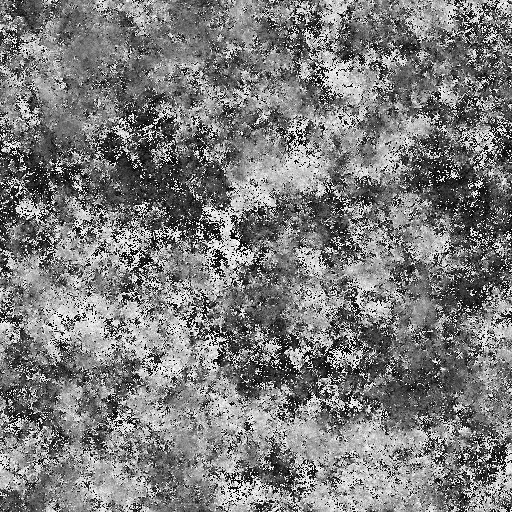
Full listing of the resulting shader
Shader "Shields/Transparent" { Properties { _ShieldIntensity("Shield Intensity", Range(0,1)) = 1.0 _ShieldColor("Shield Color", Color) = (1, 0, 0, 1) _MainTex ("Transparency Mask", 2D) = "white" {} } SubShader { Tags { "Queue"="Transparent" "RenderType"="Transparent" } ZWrite Off Blend SrcAlpha OneMinusSrcAlpha Pass { CGPROGRAM #pragma vertex vert #pragma fragment frag #include "UnityCG.cginc" struct appdata { float4 vertex : POSITION; float3 normal: NORMAL; float2 uv : TEXCOORD0; }; struct v2f { float2 uv : TEXCOORD0; float4 vertex : SV_POSITION; }; sampler2D _MainTex; float4 _MainTex_ST; float4 _ShieldColor; v2f vert (appdata v) { v2f o; o.vertex = UnityObjectToClipPos(v.vertex); o.uv = TRANSFORM_TEX(v.uv, _MainTex); return o; } float _ShieldIntensity; fixed4 frag (v2f i) : SV_Target { // sample the texture fixed4 transparencyMask = tex2D(_MainTex, i.uv); return fixed4(_ShieldColor.r, _ShieldColor.g, _ShieldColor.b, _ShieldIntensity * transparencyMask.r); } ENDCG } } } While not very good, but this is the base on which the whole effect will be built.
Fresnel effect
In general, the Fresnel effect is the effect of increasing the intensity of the reflected beam with increasing its angle of incidence. But I use the formulas used in the calculation of this effect to set the dependence of the intensity of the glow of the shield on the viewing angle.
We start implementation using the approximate formula from cg tutorial on nvidia
where I is the direction from the camera to the top, N is the normal of the surface at the point of incidence
- First, copy the shader to a new file and rename it to Shields / Fresnel to have a history of changes.
- As you can see from the formula, we will need 3 new parameters for the
Bias,shader
Scale, PowerBias,
Scale, PowerBias,
Scale, PowerBias,. I expect that the reader has already learned how to add parameters to the shader and will not provide detailed instructions on how to do this. In case of difficulties, you can always see the full code at the end of the section.
Scale, Power - Calculate I and N in the vertex shader. The vertex shader in our shader is the function
v2f vert (appdata v)return value is thev2fstructure described earlier, andappdatais the vertex parameters taken from the mesh.What is appdatastruct appdata { float4 vertex : POSITION; float3 normal: NORMAL; float2 uv : TEXCOORD0; };vertex-vertexcoordinates in local coordinatesnormal- the surface normal specified for this vertexuv- vertex texture coordinates
I - the direction from the camera to the top in world coordinates - can be calculated as the difference of the world coordinates of the top and the world coordinates of the camera. In Unity shaders, the transition matrix from local to world coordinates is available in theunity_ObjectToWorldvariable, and the world camera coordinates in the_WorldSpaceCameraPosvariable. Knowing this, you can calculate I with the following lines in the vertex shader code:float4 worldVertex = mul(unity_ObjectToWorld, v.vertex); float3 I = normalize(worldVertex - _WorldSpaceCameraPos.xyz);
N is the surface normal in world coordinates - it is even easier to calculate:float3 normWorld = normalize(mul(unity_ObjectToWorld, v.normal)); - Now you can calculate the shield opacity using the Fresnel effect formula:
float fresnel = _Bias + _Scale * pow(1.0 + dot(I, normWorld), _Power);
You may notice that the value of fresnel with certain values of variables may be less than 0, this will give color artifacts when drawing. Restrict the value of a variable to the interval [0; 1] using thesaturatefunction:float fresnel = saturate(_Bias + _Scale * pow(1.0 + dot(I, normWorld), _Power)); - It remains only to transfer this value to the pixel shader. To do this, add the intensity field to the v2f structure:
struct v2f { float2 uv : TEXCOORD0; float intensity : COLOR0; float4 vertex : SV_POSITION; };
(COLOR0is semantics, the explanation of what it is is beyond the scope of this article, those interested can read about semantics in hlsl).
Now we can fill this field in the vertex shader and use it in the fragment:v2f vert (appdata v) { v2f o; o.vertex = UnityObjectToClipPos(v.vertex); o.uv = TRANSFORM_TEX(v.uv, _MainTex); float4 worldVertex = mul(unity_ObjectToWorld, v.vertex); float3 normWorld = normalize(mul(unity_ObjectToWorld, v.normal)); float3 I = normalize(worldVertex - _WorldSpaceCameraPos.xyz); float fresnel = saturate(_Bias + _Scale * pow(1.0 + dot(I, normWorld), _Power)); o.intensity = fresnel; return o; } float _ShieldIntensity; fixed4 frag (v2f i) : SV_Target { // sample the texture fixed4 transparencyMask = tex2D(_MainTex, i.uv); return fixed4(_ShieldColor.r, _ShieldColor.g, _ShieldColor.b, (_ShieldIntensity + i.intensity) * transparencyMask.r); }
You may notice that now you can add_ShieldIntensityandi.intensityeven in the vertex shader, soi.intensitydo it.
Done! After playing with the parameters of the Fresnel equation, you can get this picture
My parameters
Bias = -0.5, Scale = 1, Power = 1
Full listing of the Fresnel effect shield
Shader "Shields/Fresnel" { Properties { _ShieldIntensity("Shield Intensity", Range(0,1)) = 1.0 _ShieldColor("Shield Color", Color) = (1, 0, 0, 1) _MainTex ("Transparency Mask", 2D) = "white" {} _Bias("Bias", float) = 1.0 _Scale("Scale", float) = 1.0 _Power("Power", float) = 1.0 } SubShader { Tags { "Queue"="Transparent" "RenderType"="Transparent" } ZWrite Off Blend SrcAlpha OneMinusSrcAlpha Pass { CGPROGRAM #pragma vertex vert #pragma fragment frag #include "UnityCG.cginc" struct appdata { float4 vertex : POSITION; float3 normal: NORMAL; float2 uv : TEXCOORD0; }; struct v2f { float2 uv : TEXCOORD0; float intensity : COLOR0; float4 vertex : SV_POSITION; }; sampler2D _MainTex; float4 _MainTex_ST; float4 _ShieldColor; float _ShieldIntensity; float _Bias; float _Scale; float _Power; v2f vert (appdata v) { v2f o; o.vertex = UnityObjectToClipPos(v.vertex); o.uv = TRANSFORM_TEX(v.uv, _MainTex); float4 worldVertex = mul(unity_ObjectToWorld, v.vertex); float3 normWorld = normalize(mul(unity_ObjectToWorld, v.normal)); float3 I = normalize(worldVertex - _WorldSpaceCameraPos.xyz); float fresnel = saturate(_Bias + _Scale * pow(1.0 + dot(I, normWorld), _Power)); o.intensity = fresnel + _ShieldIntensity; return o; } fixed4 frag (v2f i) : SV_Target { // sample the texture fixed4 transparencyMask = tex2D(_MainTex, i.uv); return fixed4(_ShieldColor.r, _ShieldColor.g, _ShieldColor.b, i.intensity * transparencyMask.r); } ENDCG } } } Now you can go to the most interesting - display hits on the shield.
Drawing hit
I will describe just one of the possible response options to the hit; it is fairly simple and cheap in performance; it looks quite nice and, unlike the simplest ones, gives a nice picture when the hits are close.
- To implement the effect, the shader needs to somehow find out at what point the hit occurred and at what time. The script on the GameObject of the shield will deal with the transfer of these arguments, and since # scripting is not the subject of this article, I will simply provide the source codes of the scripts:Listing script for an object with a shield
public class ShieldHitter : MonoBehaviour { private static int[] hitInfoId = new[] { Shader.PropertyToID("_WorldHitPoint0"), Shader.PropertyToID("_WorldHitPoint1"), Shader.PropertyToID("_WorldHitPoint2") }; private static int[] hitTimeId = new[] { Shader.PropertyToID("_HitTime0"), Shader.PropertyToID("_HitTime1"), Shader.PropertyToID("_HitTime2") }; private Material material; void Start() { if (material == null) { material = this.gameObject.GetComponent<MeshRenderer>().material; } } int lastHit = 0; public void OnHit(Vector3 point, Vector3 direction) { material.SetVector(hitInfoId[lastHit], point); material.SetFloat(hitTimeId[lastHit], Time.timeSinceLevelLoad); lastHit++; if (lastHit >= hitInfoId.Length) lastHit = 0; } void OnCollisionEnter(Collision collision) { OnHit(collision.contacts[0].point, Vector3.one); } }Listing script for camerausing UnityEngine; [ExecuteInEditMode] public class CameraControls : MonoBehaviour { private const int minDistance = 25; private const int maxDistance = 25; private const float minTheta = 0.01f; private const float maxTheta = Mathf.PI - 0.01f; private const float minPhi = 0; private const float maxPhi = 2 * Mathf.PI ; [SerializeField] private Transform _target; [SerializeField] private Camera _camera; [SerializeField] [Range(minDistance, maxDistance)] private float _distance = 25; [SerializeField] [Range(minTheta, maxTheta)] private float _theta = 1; [SerializeField] [Range(minPhi, maxPhi)] private float _phi = 2.5f; [SerializeField] private float _angleSpeed = 2.0f; [SerializeField] private float _distanceSpeed = 2.0f; // Update is called once per frame void Update () { if (_target == null || _camera == null) { return; } if (Application.isPlaying) { if (Input.GetKey(KeyCode.Q)) { _distance += _distanceSpeed * Time.deltaTime; } if (Input.GetKey(KeyCode.E)) { _distance -= _distanceSpeed * Time.deltaTime; } Mathf.Clamp(_distance, minDistance, maxDistance); if (Input.GetKey(KeyCode.A)) { _phi += _angleSpeed * Time.deltaTime; } if (Input.GetKey(KeyCode.D)) { _phi -= _angleSpeed * Time.deltaTime; } _phi = _phi % (maxPhi); if (Input.GetKey(KeyCode.S)) { _theta += _angleSpeed * Time.deltaTime; } if (Input.GetKey(KeyCode.W)) { _theta -= _angleSpeed * Time.deltaTime; } _theta = Mathf.Clamp(_theta, minTheta, maxTheta); Vector3 newCoords = new Vector3 { x = _distance * Mathf.Sin(_theta) * Mathf.Cos(_phi), z = _distance * Mathf.Sin(_theta) * Mathf.Sin(_phi), y = _distance * Mathf.Cos(_theta) }; this.transform.position = newCoords + _target.position; this.transform.LookAt(_target); if (Input.GetMouseButtonDown(0)) { Ray ray = _camera.ScreenPointToRay(Input.mousePosition); RaycastHit hit; var isHit = Physics.Raycast(ray, out hit); if (isHit) { ShieldHitter handler = hit.collider.gameObject.GetComponent<ShieldHitter>(); Debug.Log(hit.point); if (handler != null) { handler.OnHit(hit.point, ray.direction); } } } } } } - Like last time, save the shader under the new name Shields / FresnelWithHits
- The idea is to calculate the perturbation of the shield from nearby hits at each point of the shield, and the earlier the hit occurs, the less its influence on the shield perturbation.
I chose the following formula:
Where:distance- the fraction of the distance to the point of contact with the maximum, [0, 1]time- the fraction of the lifetime of the maximum, [0, 1]
Thus, the intensity is inversely proportional to the distance to the collision point,
proportional to the time remaining until the end of the action of the hit, and also equal to 0 with a distance equal to or greater than the maximum and with a remaining time equal to 0.
I would like to find a function that would satisfy these conditions without the need to limit the range of time and distance, but this one is all that I have. - Drawing effects of hit in shaders inevitably imposes restrictions on the number of simultaneously processed hits, for example, I chose 3 simultaneously displayed hits. Add the WorldHitPoint0, WorldHitPoint1, WorldHitPoint2, HitTime0, HitTime1, HitTime2 input parameters to the shader - a pair for each simultaneously processed hit. We will also need the MaxDistance parameters - the maximum distance to which the shield perturbation from falling extends, and HitDuration - the duration of the shield perturbation from falling.
- For each hit we will calculate in the vertex shader time and distance
float t0 = saturate((_Time.y - _HitTime0) / _HitDuration); float d0 = saturate(distance(worldVertex.xyz, _WorldHitPoint0.xyz) / (_MaxDistance)); float t1 = saturate((_Time.y - _HitTime1) / _HitDuration); float d1 = saturate(distance(worldVertex.xyz, _WorldHitPoint1.xyz) / (_MaxDistance)); float t2 = saturate((_Time.y - _HitTime2) / _HitDuration); float d2 = saturate(distance(worldVertex.xyz, _WorldHitPoint2.xyz) / (_MaxDistance));
and calculate the total intensity of hits by the formula:float hitIntensity = (1 - t0) * ((1 / (d0)) - 1) + (1 - t1) * ((1 / (d1)) - 1) + (1 - t2) * ((1 / (d2)) - 1);
It remains only to add the intensity of the shield from hits with the intensity of other effects:o.intensity = fresnel + _ShieldIntensity + hitIntensity; - We adjust the material, set the correct values of the distance and voila:
Already good enough, right? But there is one problem. The hits on the back of the shield are not visible. The reason for this is that, by default, polygons, the normal of which is directed from the camera, are not drawn. To force the graphics engine to draw them, you need to add the lineCull offafterZWrite Off. But here too the problem awaits us:
The Fresnel effect, implemented in the last section, highlights all the polygons looking from the camera - you'll have to change the formula tofloat dt = dot(I, normWorld); fresnel = saturate(_Bias + _Scale * pow(1.0 - dt * dt, _Power));
Since the original formula is already an approximation, the use of a square does not have a significant effect on the result (it can be corrected by other parameters) and allows you not to add an expensive branch operator and not to use expensive sqrt.
Run, check and:
Now everything is very good. - The final touch remains: to give the effect of “vividness”, you can add the current time to the texture coordinates of the noise to create the effect of the movement of the shield on the sphere.
o.uv = TRANSFORM_TEX(v.uv, _MainTex) + _Time.x / 6;
Final result:
Listing the final version of the shader
Shader "Shields/FresnelWithHits" { Properties { _ShieldIntensity("Shield Intensity", Range(0,1)) = 1.0 _ShieldColor("Shield Color", Color) = (1, 0, 0, 1) _MainTex ("Transparency Mask", 2D) = "white" {} _Bias("Bias", float) = 1.0 _Scale("Scale", float) = 1.0 _Power("Power", float) = 1.0 _WorldHitPoint0("Hit Point 0", Vector) = (0, 1, 0, 0) _WorldHitTime0("Hit Time 0", float) = -1000 _WorldHitPoint1("Hit Point 1", Vector) = (0, 1, 0, 0) _WorldHitTime1("Hit Time 1", float) = -1000 _WorldHitPoint2("Hit Point 2", Vector) = (0, 1, 0, 0) _WorldHitTime2("Hit Time 2", float) = -1000 _HitDuration("Hit Duration", float) = 10.0 _MaxDistance("MaxDistance", float) = 0.5 } SubShader { Tags { "Queue" = "Transparent" "RenderType" = "Transparent" } ZWrite Off Cull Off Blend SrcAlpha OneMinusSrcAlpha Pass { CGPROGRAM #pragma vertex vert #pragma fragment frag #include "UnityCG.cginc" struct appdata { float4 vertex : POSITION; float3 normal: NORMAL; float2 uv : TEXCOORD0; }; struct v2f { float2 uv : TEXCOORD0; float intensity : COLOR0; float4 vertex : SV_POSITION; }; sampler2D _MainTex; float4 _MainTex_ST; float4 _ShieldColor; float _ShieldIntensity; float _Bias; float _Scale; float _Power; float _MaxDistance; float _HitDuration; float _HitTime0; float4 _WorldHitPoint0; float _HitTime1; float4 _WorldHitPoint1; float _HitTime2; float4 _WorldHitPoint2; v2f vert (appdata v) { v2f o; o.vertex = UnityObjectToClipPos(v.vertex); o.uv = TRANSFORM_TEX(v.uv, _MainTex) + _Time.x / 6; float4 worldVertex = mul(unity_ObjectToWorld, v.vertex); float3 normWorld = normalize(mul(unity_ObjectToWorld, v.normal)); float3 I = normalize(worldVertex - _WorldSpaceCameraPos.xyz); float fresnel = 0; float dt = dot(I, normWorld); fresnel = saturate(_Bias + _Scale * pow(1.0 - dt * dt, _Power)); float t0 = saturate((_Time.y - _HitTime0) / _HitDuration); float d0 = saturate(distance(worldVertex.xyz, _WorldHitPoint0.xyz) / (_MaxDistance)); float t1 = saturate((_Time.y - _HitTime1) / _HitDuration); float d1 = saturate(distance(worldVertex.xyz, _WorldHitPoint1.xyz) / (_MaxDistance)); float t2 = saturate((_Time.y - _HitTime2) / _HitDuration); float d2 = saturate(distance(worldVertex.xyz, _WorldHitPoint2.xyz) / (_MaxDistance)); float hitIntensity = (1 - t0) * ((1 / (d0)) - 1) + (1 - t1) * ((1 / (d1)) - 1) + (1 - t2) * ((1 / (d2)) - 1); o.intensity = fresnel + _ShieldIntensity + hitIntensity; return o; } fixed4 frag (v2f i) : SV_Target { // sample the texture fixed4 transparencyMask = tex2D(_MainTex, i.uv); return fixed4(_ShieldColor.r, _ShieldColor.g, _ShieldColor.b, saturate(i.intensity * transparencyMask.r)); } ENDCG } } } Exactly what is needed.
That's so easy and not too expensive, you can get quite a beautiful effect of the shield of the spacecraft.
Instead of an afterword: optimization
I will outline the main directions of possible optimization:
- Remove unused: Fresnel effect, basic translucent shield - all this is not free and if some of the components are not needed, you need to remove them.
- t0, t1, t2 can be counted on the CPU once per frame for each shield in the script. Thus, you can remove 3 saturate and a bunch of calculations.
- Using floating-point numbers with less precision, in many places you can get fixed or even half instead of float.
- If many shields are drawn on the screen, it makes sense to consider using instancing.
Source: https://habr.com/ru/post/352228/
All Articles