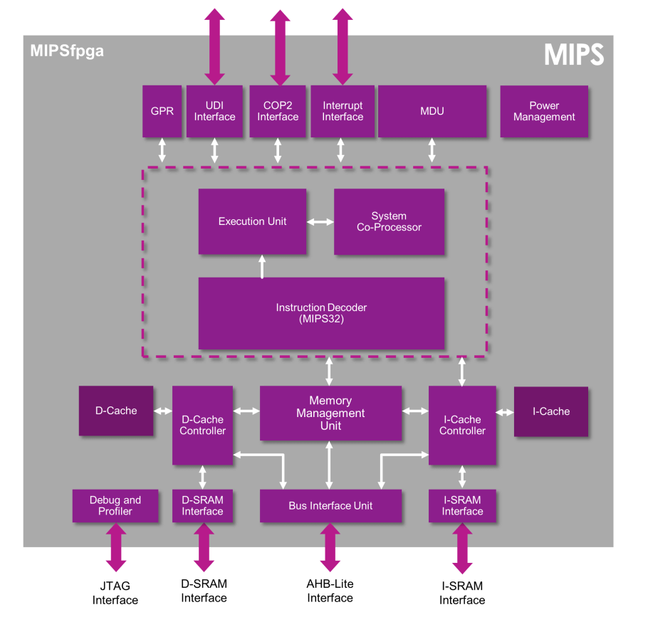
About porting the MIPSfpga project
Transferring software from one computer architecture to another in principle, with some reservations, is relatively simple. Here well-known tools such as autoconf / automake / libtool / gnulib come to the rescue. Building a program from source on some kind of Raspberry / ARM is as easy as on a PC with Ubuntu / x86-64.
But how to make the FPGA project designed for one board to work on another board? There the FPGA itself may be different and completely different components may stand on the board. Simple recompilation of the project is not enough.
')
I'll tell you about my experience in porting the MIPSfpga project for the Mars Rover3 board with MAX10 Intel FPGA. Articles about the project MIPSfpga repeatedly appeared on Habré. They were so interesting that I wanted to try this project myself in the board I had. In my work, I relied on Habrovsk articles
And many others…
So, what should be done to port the FPGA project to another board?
1) It is necessary to reassign the type of FPGA used in the project
Lucky if the original project is focused on the exact same FPGA chip as on your board. The MIPSfpga project has already been ported to boards from different manufacturers, including, there are boards with FPGA Xilinx and boards with FPGA Intel / Altera. Nevertheless, let's say, I am “not lucky.” Yes, there is a project for the DE10-lite board and it uses the MAX10 FPGA, as on my board. But this is a completely different MAX10 - on the DE10-lite it costs 10M50DAF484C7G, and on the Mars Rover3 there is a FPGA MAX1050SAE144C8. Both microcircuits have 50 thousand logical elements, but the first one has much more input / output signals. It is clear that together with the reassignment of the FPGA chip type, all the signal assignments to the specific outputs of the chip “fly off”.
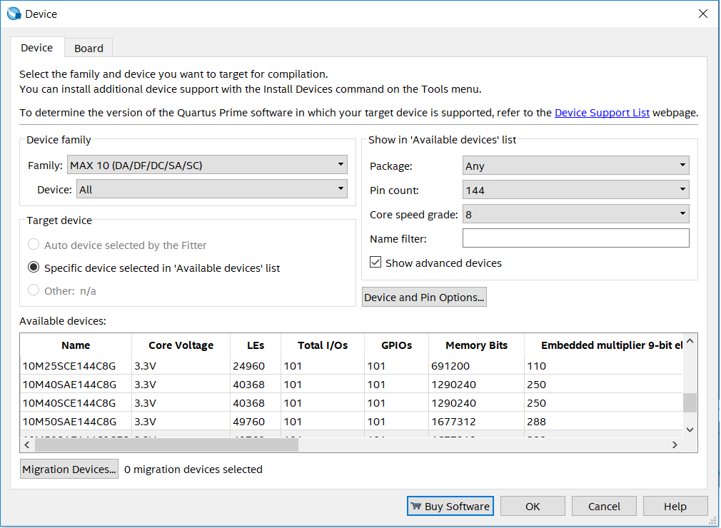
The type of chip used in the Intel Quartus CAD system is assigned via the menu Assignments => Device in the Device dialog box.
There is also a button Device And Pin Options - go there in the next dialog box and I highly recommend immediately indicating that pins that are not used in the project should be As input tri-state.

If the board is not very familiar, we have not yet thoroughly studied its scheme, for example, it is better to disconnect the unused FPGA conclusions from the board circuits.
2) Make new appointments for entrances and exits
Since the type of the chip has been reassigned, it is now necessary to indicate which inputs / outputs are those or other signals of the FPGA project. In each FPGA project there is a top-level module. The signals of this module are connected to the outputs of the FPGA chip, with those to which we indicate in the project settings.
For example, in my project:
module m3 ( input MAX10_CLK_100, input [ 1:0] KEY, output [ 7:0] LEDR, input wire FTDI_RX, output wire FTDI_TX, inout wire [7:0]FTD, `ifdef MFP_USE_SDRAM_MEMORY output [11:0] DRAM_ADDR, output [ 1:0] DRAM_BA, output DRAM_CAS_N, //output DRAM_CKE, output DRAM_CLK, //output DRAM_CS_N, inout [15:0] DRAM_DQ, output DRAM_LDQM, output DRAM_RAS_N, output DRAM_UDQM, output DRAM_WE_N, `endif `ifdef UNUSED input ADC_CLK_10, input MAX10_CLK1_50, input MAX10_CLK2_50, input [ 9:0] SW, output [ 7:0] HEX0, output [ 7:0] HEX1, output [ 7:0] HEX2, output [ 7:0] HEX3, output [ 7:0] HEX4, output [ 7:0] HEX5, output [ 3:0] VGA_B, output [ 3:0] VGA_G, output VGA_HS, output [ 3:0] VGA_R, output VGA_VS, output GSENSOR_CS_N, input [ 2:1] GSENSOR_INT, output GSENSOR_SCLK, inout GSENSOR_SDI, inout GSENSOR_SDO, inout [15:0] ARDUINO_IO, inout ARDUINO_RESET_N, inout [35:0] GPIO, `endif inout [15:0] GPIO, //HDMI output output wire [7:0]TMDS ); On the Mars Rover3, there are neither SW switches, nor seven-segment indicators HEX0..HEX5, nor a VGA connector. I did not directly remove these signals from the project, but deleted them by conditional compilation using the `if UNUSED ...` endif construct. There are LEDs, buttons, signals from FTDI, and even HDMI signals on the Mars Rover3 board — here they are in my project.
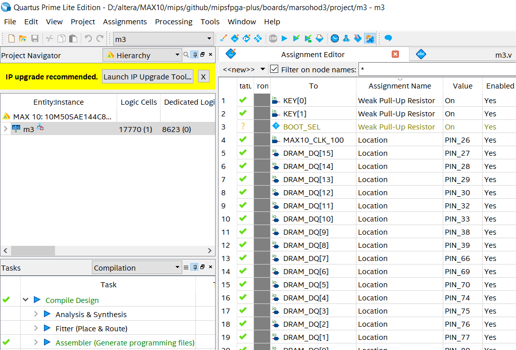
In the Quartus environment, through the Assigments => Assignment Editor menu, you need to set the corresponding signal to the contact number of the chip. Of course, this should be done according to the circuit diagram of the electric principal. In addition to specifying the chip output number, you may need to make other assignments like i / O Standard or Pull-Up Resistor, if necessary.
3) Attention to the clock frequency
It is likely that the original project was made for a card whose face value of a quartz oscillator is not the same as on our board. So it turned out in my case. The DE10-lite has a 50 MHz oscillator, and my board has a 100 MHz one. What you need to do is re-create an instance of the PLL module for this project. In the menu of the quarter, select Tools => IP Catalog, where among the Installed IPs => Libraries we find basic Functions => Clocks; PLLs and Reset => PLLs => ALTPLL and run the Wizard.
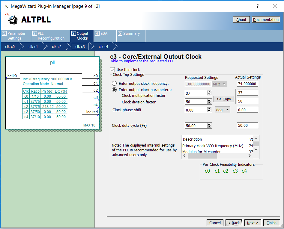
You need to specify the correct source frequency and set the desired output frequency in the PLL. There will have to take into account many factors. I decided to add to the project an output to the HDMI display, which was not in the original project, which means I needed the additional frequencies required directly for the formation of the TMDS video signals (74 MHz and 370 MHz).
The created variation of the PLL component must then be inserted into the project.
4) Trim or expand functionality?
In the case of porting FPGA projects to other boards, you often encounter the fact that you will not be able to repeat the project one-to-one. The simplest reason is, for example, the initial project is made for a board that has 16 LEDs and / or seven-segment indicators, but on our board, for example, there is no such thing at all, or there are LEDs, but they are fewer, not sixteen, but only eight. Or the board has a different amount of RAM or flash ... Then you have to think of something, somehow bypass the restrictions.
I decided that since the project MIPSfpga training and display information is really somehow necessary, but otherwise the “visuality of the project” is lost, then I will display information on the monitor.
For this purpose, I wrote a module of virtual LEDs and seven-segment indicators on Verilog.
I will give the text of the module here:
Virtual LED and Indicator Module
//marsohod3 board has only 8 yellow LEDs //but sample MIPS needs red/green LEDs and 7-segment indicators //so try display LEDs and 7-segment info on HDMI output of Marsohod3 board module display ( input wire reset, input wire clk_video, //74MHz input wire clk_hdmi, //370MHz input wire [NUM_RED_LEDS-1:0]red_leds, input wire [NUM_GREEN_LEDS-1:0]green_leds, input wire [NUM_SEGMENTS*4-1:0]segments, //HDMI output output wire [7:0]TMDS ); parameter NUM_RED_LEDS = 16; parameter NUM_GREEN_LEDS = 16; parameter NUM_SEGMENTS = 6; wire w_hsync; wire w_vsync; wire w_active; wire [11:0]w_pixel_count; wire [11:0]w_line_count; wire w_video_clk5; assign w_video_clk5 = clk_hdmi; wire w_video_clk; assign w_video_clk = clk_video; hvsync u_hvsync( .reset( reset ), .pixel_clock( w_video_clk ), .hsync(w_hsync), .vsync(w_vsync), .active(w_active), .pixel_count(w_pixel_count), .line_count(w_line_count), .dbg( ) ); reg d_active; reg r_hsync; reg r_vsync; reg r_vsync_; reg [NUM_RED_LEDS-1:0]red_leds_fixed; reg [NUM_GREEN_LEDS-1:0]green_leds_fixed; reg [NUM_SEGMENTS*4-1:0]segments_fixed; always @(posedge w_video_clk) begin r_hsync <= w_hsync; r_vsync <= w_vsync; r_vsync_ <= r_vsync; d_active <= w_active; if( r_vsync_==1'b0 && r_vsync==1'b1 ) begin red_leds_fixed <= red_leds; green_leds_fixed <= green_leds; segments_fixed <= segments; end end reg [9:0]red_word; reg [9:0]green_word; reg [9:0]blue_word; wire led_visible; assign led_visible = w_pixel_count<512 && w_pixel_count[4]==1'b1; wire [3:0]led_idx; assign led_idx = NUM_RED_LEDS-1-w_pixel_count[8:5]; wire current_green_led = (green_leds_fixed >> led_idx)&1; wire current_red_led = (red_leds_fixed >> led_idx)&1; wire h_seg_line5; assign h_seg_line5 = w_pixel_count<(64*1-8) && w_pixel_count>(64*0+32); wire h_seg_line4; assign h_seg_line4 = w_pixel_count<(64*2-8) && w_pixel_count>(64*1+32); wire h_seg_line3; assign h_seg_line3 = w_pixel_count<(64*3-8) && w_pixel_count>(64*2+32); wire h_seg_line2; assign h_seg_line2 = w_pixel_count<(64*4-8) && w_pixel_count>(64*3+32); wire h_seg_line1; assign h_seg_line1 = w_pixel_count<(64*5-8) && w_pixel_count>(64*4+32); wire h_seg_line0; assign h_seg_line0 = w_pixel_count<(64*6-8) && w_pixel_count>(64*5+32); wire vl_seg_line5; assign vl_seg_line5 = w_pixel_count<(64*1-32) && w_pixel_count>(64*0+24); wire vl_seg_line4; assign vl_seg_line4 = w_pixel_count<(64*2-32) && w_pixel_count>(64*1+24); wire vl_seg_line3; assign vl_seg_line3 = w_pixel_count<(64*3-32) && w_pixel_count>(64*2+24); wire vl_seg_line2; assign vl_seg_line2 = w_pixel_count<(64*4-32) && w_pixel_count>(64*3+24); wire vl_seg_line1; assign vl_seg_line1 = w_pixel_count<(64*5-32) && w_pixel_count>(64*4+24); wire vl_seg_line0; assign vl_seg_line0 = w_pixel_count<(64*6-32) && w_pixel_count>(64*5+24); wire vr_seg_line5; assign vr_seg_line5 = w_pixel_count<(64*1) && w_pixel_count>(64*0+56); wire vr_seg_line4; assign vr_seg_line4 = w_pixel_count<(64*2) && w_pixel_count>(64*1+56); wire vr_seg_line3; assign vr_seg_line3 = w_pixel_count<(64*3) && w_pixel_count>(64*2+56); wire vr_seg_line2; assign vr_seg_line2 = w_pixel_count<(64*4) && w_pixel_count>(64*3+56); wire vr_seg_line1; assign vr_seg_line1 = w_pixel_count<(64*5) && w_pixel_count>(64*4+56); wire vr_seg_line0; assign vr_seg_line0 = w_pixel_count<(64*6) && w_pixel_count>(64*5+56); function [7:0]seg7; input [3:0]a; begin case(a) 0: seg7 = 63; 1: seg7 = 6; 2: seg7 = 91; 3: seg7 = 79; 4: seg7 = 102; 5: seg7 = 109; 6: seg7 = 125; 7: seg7 = 7; 8: seg7 = 127; 9: seg7 = 111; 10: seg7 = 119; 11: seg7 = 124; 12: seg7 = 57; 13: seg7 = 94; 14: seg7 = 121; 15: seg7 = 113; endcase end endfunction reg [6:0]seg7_0; reg [6:0]seg7_1; reg [6:0]seg7_2; reg [6:0]seg7_3; reg [6:0]seg7_4; reg [6:0]seg7_5; always @(posedge clk_video) begin seg7_0 <= seg7( segments_fixed[ 3: 0] ); seg7_1 <= seg7( segments_fixed[ 7: 4] ); seg7_2 <= seg7( segments_fixed[11: 8] ); seg7_3 <= seg7( segments_fixed[15:12] ); seg7_4 <= seg7( segments_fixed[19:16] ); seg7_5 <= seg7( segments_fixed[23:20] ); end reg [2:0]color; always @* begin if( w_line_count>64 && w_line_count<80 ) begin //green led line if(led_visible) color = current_green_led ? 1 : 2; else color=0; end else if( w_line_count>96 && w_line_count<112 ) begin //red led line if(led_visible) color = current_red_led ? 3 : 4; else color=0; end else if( w_line_count>118+32 && w_line_count<126+32 ) begin // 7seg top line if(h_seg_line0) color = seg7_0[0] ? 5 : 6; else if(h_seg_line1) color = seg7_1[0] ? 5 : 6; else if(h_seg_line2) color = seg7_2[0] ? 5 : 6; else if(h_seg_line3) color = seg7_3[0] ? 5 : 6; else if(h_seg_line4) color = seg7_4[0] ? 5 : 6; else if(h_seg_line5) color = seg7_5[0] ? 5 : 6; else color=0; end else if( w_line_count>126+32 && w_line_count<148+32 ) begin if(vr_seg_line0) color = seg7_0[1] ? 5 : 6; else if(vr_seg_line1) color = seg7_1[1] ? 5 : 6; else if(vr_seg_line2) color = seg7_2[1] ? 5 : 6; else if(vr_seg_line3) color = seg7_3[1] ? 5 : 6; else if(vr_seg_line4) color = seg7_4[1] ? 5 : 6; else if(vr_seg_line5) color = seg7_5[1] ? 5 : 6; else if(vl_seg_line0) color = seg7_0[5] ? 5 : 6; else if(vl_seg_line1) color = seg7_1[5] ? 5 : 6; else if(vl_seg_line2) color = seg7_2[5] ? 5 : 6; else if(vl_seg_line3) color = seg7_3[5] ? 5 : 6; else if(vl_seg_line4) color = seg7_4[5] ? 5 : 6; else if(vl_seg_line5) color = seg7_5[5] ? 5 : 6; else color=0; end else if( w_line_count>148+32 && w_line_count<156+32 ) begin // 7seg middle line if(h_seg_line0) color = seg7_0[6] ? 5 : 6; else if(h_seg_line1) color = seg7_1[6] ? 5 : 6; else if(h_seg_line2) color = seg7_2[6] ? 5 : 6; else if(h_seg_line3) color = seg7_3[6] ? 5 : 6; else if(h_seg_line4) color = seg7_4[6] ? 5 : 6; else if(h_seg_line5) color = seg7_5[6] ? 5 : 6; else color=0; end else if( w_line_count>156+32 && w_line_count<180+32 ) begin if(vr_seg_line0) color = seg7_0[2] ? 5 : 6; else if(vr_seg_line1) color = seg7_1[2] ? 5 : 6; else if(vr_seg_line2) color = seg7_2[2] ? 5 : 6; else if(vr_seg_line3) color = seg7_3[2] ? 5 : 6; else if(vr_seg_line4) color = seg7_4[2] ? 5 : 6; else if(vr_seg_line5) color = seg7_5[2] ? 5 : 6; else if(vl_seg_line0) color = seg7_0[4] ? 5 : 6; else if(vl_seg_line1) color = seg7_1[4] ? 5 : 6; else if(vl_seg_line2) color = seg7_2[4] ? 5 : 6; else if(vl_seg_line3) color = seg7_3[4] ? 5 : 6; else if(vl_seg_line4) color = seg7_4[4] ? 5 : 6; else if(vl_seg_line5) color = seg7_5[4] ? 5 : 6; else color=0; end else if( w_line_count>180+32 && w_line_count<188+32 ) begin // 7seg bottom line if(h_seg_line0) color = seg7_0[3] ? 5 : 6; else if(h_seg_line1) color = seg7_1[3] ? 5 : 6; else if(h_seg_line2) color = seg7_2[3] ? 5 : 6; else if(h_seg_line3) color = seg7_3[3] ? 5 : 6; else if(h_seg_line4) color = seg7_4[3] ? 5 : 6; else if(h_seg_line5) color = seg7_5[3] ? 5 : 6; else color=0; end else color=0; end reg [2:0]color_fixed; always @(posedge clk_video) color_fixed<=color; always @* begin case(color_fixed) 0: begin //gray red_word = 10'b0000011111; green_word = 10'b0000011111; blue_word = 10'b0000111111; end 1: begin //bright green red_word = 10'b0000011111; green_word = 10'b1111111111; blue_word = 10'b0000011111; end 2: begin //dark green red_word = 10'b0000011111; green_word = 10'b0000111111; blue_word = 10'b0000011111; end 3: begin //bright red red_word = 10'b1111111111; green_word = 10'b0000011111; blue_word = 10'b0000011111; end 4: begin //dark red red_word = 10'b0000111111; green_word = 10'b0000011111; blue_word = 10'b0000011111; end 5: begin //bright yellow red_word = 10'b1111111111; green_word = 10'b1111111111; blue_word = 10'b0000011111; end 6: begin //dark yellow red_word = 10'b0000111111; green_word = 10'b0000111111; blue_word = 10'b0000011111; end 7: begin //gray red_word = 10'b0000011111; green_word = 10'b0000011111; blue_word = 10'b0000111111; end endcase end wire w_tmds_bh; wire w_tmds_bl; wire w_tmds_gh; wire w_tmds_gl; wire w_tmds_rh; wire w_tmds_rl; hdmi u_hdmi( .pixclk( w_video_clk ), .clk_TMDS2( w_video_clk5 ), .hsync( r_hsync ), .vsync( r_vsync ), .active( d_active ), .red( red_word ), .green( green_word ), .blue( blue_word ), .TMDS_bh( w_tmds_bh ), .TMDS_bl( w_tmds_bl ), .TMDS_gh( w_tmds_gh ), .TMDS_gl( w_tmds_gl ), .TMDS_rh( w_tmds_rh ), .TMDS_rl( w_tmds_rl ) ); altddio_out1 u_ddio1( .datain_h( w_video_clk), .datain_l( w_video_clk), .outclock(w_video_clk5), .dataout( TMDS[1] ) ); altddio_out1 u_ddio0( .datain_h(~w_video_clk), .datain_l(~w_video_clk), .outclock(w_video_clk5), .dataout( TMDS[0] ) ); altddio_out1 u_ddio3( .datain_h( w_tmds_bh), .datain_l( w_tmds_bl), .outclock(w_video_clk5), .dataout( TMDS[3] ) ); altddio_out1 u_ddio2( .datain_h(~w_tmds_bh), .datain_l(~w_tmds_bl), .outclock(w_video_clk5), .dataout( TMDS[2] ) ); altddio_out1 u_ddio5( .datain_h( w_tmds_gh), .datain_l( w_tmds_gl), .outclock(w_video_clk5), .dataout( TMDS[5] ) ); altddio_out1 u_ddio4( .datain_h(~w_tmds_gh), .datain_l(~w_tmds_gl), .outclock(w_video_clk5), .dataout( TMDS[4] ) ); altddio_out1 u_ddio7( .datain_h( w_tmds_rh), .datain_l( w_tmds_rl), .outclock(w_video_clk5), .dataout( TMDS[7] ) ); altddio_out1 u_ddio6( .datain_h(~w_tmds_rh), .datain_l(~w_tmds_rl), .outclock(w_video_clk5), .dataout( TMDS[6] ) ); endmodule Here is the entire project source code for the Mars Rover 3 board , which demonstrates the display of a binary counter on virtual LEDs.
But his video demonstration:
It seems to me that it turned out pretty nice.
Thus, with the help of virtual LEDs and seven-segment indicators, I managed to save a significant part of the MIPSfpga project when porting to a board that does not physically have 32 LEDs and does not have 7 segment indicators.
Next, I will show how the MIPSfpga project is loaded into the board:
This video demonstration shows how the FPGA board is loaded from a laptop from the Quartus Prime CAD system and immediately after the FPGA download, the connected HDMI monitor receives synchronization. Then the test program is compiled on the laptop and loaded into the board and launched on the MIPS processor in the FPGA.
Here are more examples of programs for MIPS:
- The memory test program 04_memtest starts, then
- the communication program 05_uart for SoC MIPSfpga and for the serial port from a PC is being investigated,
- running program 06_timer_irq using hardware interrupts
- 09_adc_0 is a testing program built into the MAX10 FPGA ADC
Well, I would also like to show how you can conduct in-circuit debugging of MIPS programs using the external MBFTDI programmer and OpenOCD and GDB programs:
You can read more about the MIPSfpga project in the Mars Rover3 board here .
In conclusion, I would like to express my gratitude to SparF , YuriPanchul , Frantony for their wonderful series of articles on MIPSfpga. Without these articles there would not be this work of mine.
Source: https://habr.com/ru/post/351672/
All Articles