Wireless LANs or how Wi-Fi works according to IEEE 802.11 standard. Lab at Packet Tracer
Introduction
In this article, the laboratory studies the wireless LAN technology according to the IEEE 802.11 standard. The IEEE standard was developed by the Institute of Electrical and Electronic Engineers. From here he got his name. This standard defines local Ethernet networks; therefore, the TCP / IP model does not define an Ethernet network in its requests for comments, but refers to IEEE Ethernet documents. All work will be performed in Cisco Packet Tracer.

')
Wireless networking concept
Many users regularly use the services and devices of wireless LANs (Wireless LAN - WLAN). At the current time, there is a growing tendency to use portable devices such as laptops, tablets, smartphones. Also, the concepts of “smart home” are being actively developed, most of the devices of which are connected “by air”. In connection with this, there was a need for wireless connection in all crowded places: at work, at home, in a hotel, in a cafe or a bookstore. With the growing number of wireless devices that connect through a WLAN network, the popularity of wireless networks has grown.
Below is a simplified diagram of the network in the "House of Books" on Nevsky Prospect in St. Petersburg.
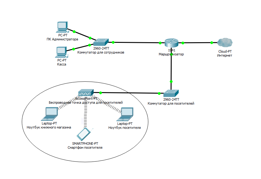
Visitor laptops interact with a WLAN device called a wireless access point (Access Point). The access point uses a radio channel to send and receive frames (individual, complete HTML documents that can be displayed in a browser window along with other HTML documents) from a client device, such as a computer. In addition, the access point is connected to the same Ethernet network as the devices providing the store, therefore, customers and employees can search for information on remote websites.
Comparing Wireless LANs with Local Area Networks
Wireless LANs are very similar to LANs, for example, both types of networks allow devices to communicate with each other. For both types of networks, the IEEE standard works (IEEE 802.3 for Ethernet and 802.11 for wireless networks). Both standards describe the format of network frames (header and trailer), states that the header should be 6 bytes in length and contain the MAC addresses of the sender and receiver. Both standards indicate exactly how devices on the network should determine when the frame can be transmitted on Wednesday and when it cannot.
The main difference between the two types of networks is that for transmitting data in wireless networks the technology uses radiation of energy (or technology of radiation of radio waves), while Ethernet uses transmission of electric pulses over a copper cable (or light pulses in an optical fiber). Radio waves do not need a special work environment, they usually say that “communication takes place over the air” to emphasize that no physical network is needed. In reality, any physical objects in the path of a radio signal (walls, metal structures, etc.) are an obstacle degrading the quality of a radio signal.
Wireless LAN Standards
IEEE defines four basic 802.11 WLAN standards: 802.11a, 802.11b, 802.11g, and 802.11n.
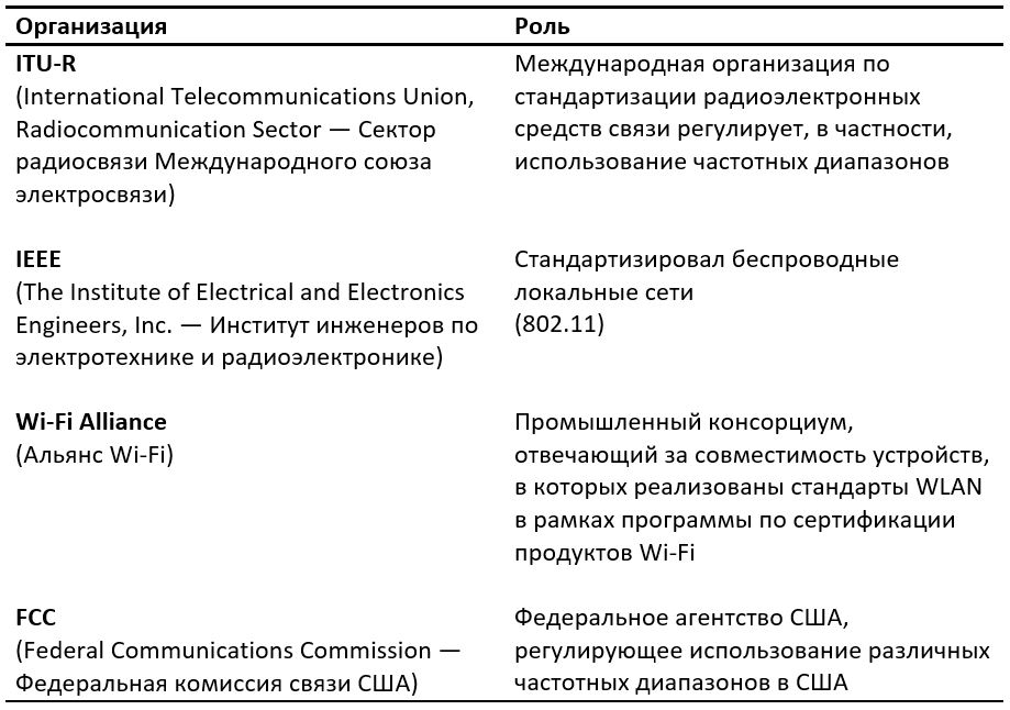
The following four organizations had the greatest impact on wireless networking standards (see table below)
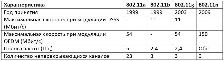
WLAN Standards Comparison
In addition to the basic standards from the table, there are additional standards that are listed below.
Also there are two recommendations. The letters with them are capitalized.
• 802.11F - Inter-Access Point Protocol (Service Data Exchange Protocol between access points. This protocol is a recommendation that describes the optional IEEE 802.11 extension that provides a wireless access point for communication between systems from different manufacturers).
• 802.11T - Wireless Performance Prediction (WPP, prediction of wireless equipment performance) - test and measurement methods (this method is a set of techniques recommended by IEEE for testing 802.11 networks: methods of measuring and processing results, requirements for test equipment).
Basic devices and conventional symbols in working with Wi-Fi
1. The access point is the wireless “extension” of the wired network.

2. A router is a smarter device that not only receives and transmits data, but also redistributes it according to various established rules and executes specified commands.

3. Cloud - configured part of the network

4. Wi-Fi connection
5. Straight line - cable (twisted pair)
Basic ways to use Wi-Fi
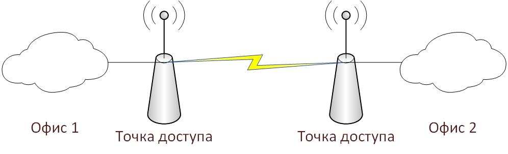
1. Wi-Fi bridge - connecting two access points via Wi-Fi
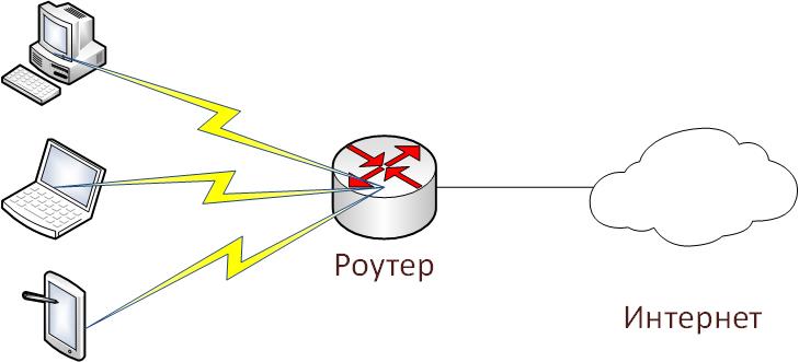
2. Wi-Fi router - connect all devices to the router via Wi-Fi (the entire network is connected wirelessly).
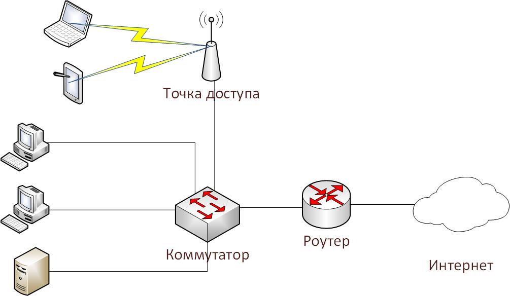
3. Wi-Fi access point - connect part of the network for wireless operation
Tasks laboratory work.
1. Create and configure the second and third Wi-Fi usage options in Cisco Packet Tracer.
2. Configure a bridge between two access points (the first option to use Wi-Fi) on real equipment.
Perform laboratory work.
Task number 1 (option network number 2)
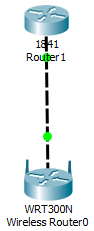
1. Create a Wi-Fi router on the working area of the Packet Tracer (aka Wi-Fi router)

2. Create a router from the provider (for example, the name of the provider is “Miry-Mir”). I chose a Cisco 1841 router.

3. We connect them with a cross-cable (dotted line), since the devices are of the same type (routers). We connect this way: one end in Router1 in FastEthernet 0/0, and the other end in Wireless Router0 to the Internet connector, since Router1 distributes the Internet to us.

4. Configure the Internet router (Router1) to work with the network. To do this, go to the settings of the router by double clicking on it and go to the tab CLI (Command Line Interface).
In the dialogue “Would you like to enter the initial configuration dialog? [yes / no]: "(you want to enter the initial configuration dialog) write" no ".
We write the following sequence of commands:
By tradition, consider them in order.
Connection established.
5. Set up a wireless router (Wireless Router0) to work with the network. To do this, as in the case of the previous router, go to the settings of the router by double clicking on it. In the tabs, select the graphical user interface (GUI - graphical user interface). This mode will be displayed when entering the router's address in any browser.
Set the following settings:
And at the bottom of the page press the button "Save settings"
Parsing settings:
We chose a static IP, since the provider gave us a white IP address (120.120.0.1/24). The default path (Default Gateway) is the address of the router from the provider. The address of the router from the wireless devices - 192.168.0.1/24. The router will distribute IP from 100 to 150.
6. Go to the Wireless tab, that is, the wireless connection.
We set the following settings:
And at the bottom of the page press the button "Save settings"
Parsing settings:
7. Set up the protection of our router. To do this, go to the Security tab and in the “Security Mode” section, select WPA2 Personal, because WPA is a vulnerable protection. There is no need to choose WPA2 Enterprise either, since for her work we need a radius server, which we did not do. The encryption algorithm is left AES and enter the code word. I set Habrahabr.
8. Add 3 devices, as in the diagram (smartphone, laptop and computer). Then replace the connectors for rj-45 to a Wi-Fi antenna (in the smartphone, the default antenna).
9. In the Config tab, set the settings that were set on the router. This operation must be done on all devices.
10. Go to the desktop of any computer and open the command line.
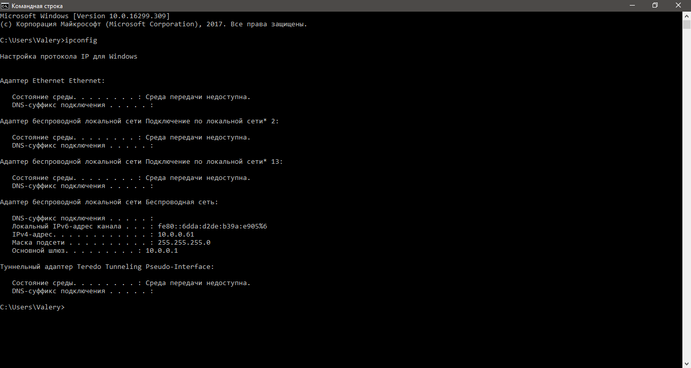
11. Check what addresses the router issued devices. To do this, enter the command ipconfig.
As can be seen in the screenshot, the router gives addresses from 192.168.0.100 to 192.168.0.150.
12. We check the network operability from any device using the ping command. We will ping 2 addresses - the address of the router (192.168.0.1) and the white address (120.120.0.1), that is, we will check if the device can access the Internet.
Again, everything works.
As a result, we got a Wi-Fi network, which is shown in the second use case.

Task number 1 (option network number 3)
1. Open the finished project from the previous PAT laboratory work .
2. Create an access point on the working area of the program and connect it to the switch. If desired, the access point can be configured (Port 0 is a physical port, and Port 1 is a wireless)
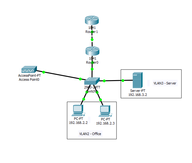
3. Create another VLAN for a wireless access point.
4. Add in the settings of the router 0 VLAN 4, and also add it to the access list to access the Internet.
Since we did this in previous labs (on VLAN and PAT ), I will not dwell in detail, but I will register all the commands on the devices
Switch
Router (subinterface)
Router (DHCP (Dynamic Host Configuration Protocol - Dynamic Host Configuration Protocol). A network protocol that allows computers to automatically obtain an IP address and other parameters necessary for work on a TCP / IP network)
I’ll stop here in more detail, since we haven’t previously met with this parameter.
Router (access list)
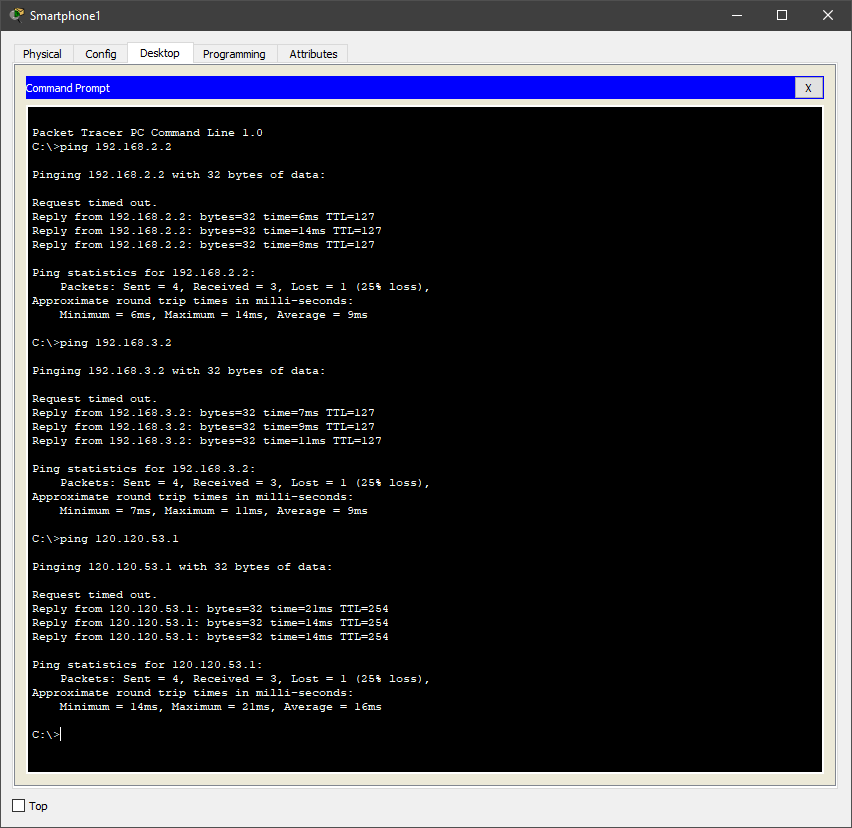
Add a smartphone to the Packet Tracer workspace and ping the PC, server and Internet, that is, 192.168.2.2, 192.168.3.2, 120.120.53.1.
As you can see, everything works.
Task number 2 (option network number 1)
Unfortunately, in Packet Tracer there is no possibility to create a Wi-Fi bridge (also known as a repeater or repeater), but we will do this simple operation on real hardware in a graphical environment.
The equipment on which the settings will be made is the ASUS RT-N10 router and the so-called TP-LINK TL-WA850RE repeater.
Let's proceed to the configuration of the Asus router. To do this, open the browser and enter the address of the router (by default it will open itself)
Go to the tab "Wireless Network" and set the setting as in the screenshot below.
Go to the tab "LAN" (local area network) and set the following settings.

Go to the main tab. There we can see our MAC address
Go to setting up the TP-LINK repeater
We automatically device will give the main menu and quick setting mode. Click "Exit" and perform the settings themselves.
Go to the tab "Network" and set the following settings.
Go to the tab "Wireless Mode" and configure the input and output stream.

In the "Profile" tab, we see all the profiles we created. Click the button "Change"
Configure output network security by adding a WPA2 key.
Go to the main menu and select the item "Connect" in the "Wireless Connection". Next will configure the bridge. It may be necessary to enter a password from an Asus router.
After clicking the button will load the configurations
And voila! All is ready!

In order not to be confused to which device to connect, you can hide the SSID on the Asus router
We check the connection by cable
Ping is successful.
Check on Wi-Fi.
Successfully.
And review the final configuration, when connected to the repeater.
In this article, the laboratory studies the wireless LAN technology according to the IEEE 802.11 standard. The IEEE standard was developed by the Institute of Electrical and Electronic Engineers. From here he got his name. This standard defines local Ethernet networks; therefore, the TCP / IP model does not define an Ethernet network in its requests for comments, but refers to IEEE Ethernet documents. All work will be performed in Cisco Packet Tracer.
')
Wireless networking concept
Many users regularly use the services and devices of wireless LANs (Wireless LAN - WLAN). At the current time, there is a growing tendency to use portable devices such as laptops, tablets, smartphones. Also, the concepts of “smart home” are being actively developed, most of the devices of which are connected “by air”. In connection with this, there was a need for wireless connection in all crowded places: at work, at home, in a hotel, in a cafe or a bookstore. With the growing number of wireless devices that connect through a WLAN network, the popularity of wireless networks has grown.
Below is a simplified diagram of the network in the "House of Books" on Nevsky Prospect in St. Petersburg.
Visitor laptops interact with a WLAN device called a wireless access point (Access Point). The access point uses a radio channel to send and receive frames (individual, complete HTML documents that can be displayed in a browser window along with other HTML documents) from a client device, such as a computer. In addition, the access point is connected to the same Ethernet network as the devices providing the store, therefore, customers and employees can search for information on remote websites.
Comparing Wireless LANs with Local Area Networks
Wireless LANs are very similar to LANs, for example, both types of networks allow devices to communicate with each other. For both types of networks, the IEEE standard works (IEEE 802.3 for Ethernet and 802.11 for wireless networks). Both standards describe the format of network frames (header and trailer), states that the header should be 6 bytes in length and contain the MAC addresses of the sender and receiver. Both standards indicate exactly how devices on the network should determine when the frame can be transmitted on Wednesday and when it cannot.
The main difference between the two types of networks is that for transmitting data in wireless networks the technology uses radiation of energy (or technology of radiation of radio waves), while Ethernet uses transmission of electric pulses over a copper cable (or light pulses in an optical fiber). Radio waves do not need a special work environment, they usually say that “communication takes place over the air” to emphasize that no physical network is needed. In reality, any physical objects in the path of a radio signal (walls, metal structures, etc.) are an obstacle degrading the quality of a radio signal.
Wireless LAN Standards
IEEE defines four basic 802.11 WLAN standards: 802.11a, 802.11b, 802.11g, and 802.11n.
The following four organizations had the greatest impact on wireless networking standards (see table below)
WLAN Standards Comparison
Terms
- DSSS (Direct sequence spread spectrum - Direct sequence method for spectrum expansion)
- OFDM (Orthogonal frequency-division multiplexing - orthogonal frequency division multiplexing)
- OFDM (Orthogonal frequency-division multiplexing - orthogonal frequency division multiplexing)
In addition to the basic standards from the table, there are additional standards that are listed below.
Additional standards
• 802.11 - the original 1 Mbit / s and 2 Mbit / s, 2.4 GHz and IR standard (1997).
• 802.11c — bridging procedures; included in the IEEE 802.1D (2001) standard.
• 802.11d - international roaming extensions (2001).
• 802.11e - enhancements: QoS, packet bursting (2005).
• 802.11h - spread spectrum 802.11a (5 GHz) for compatibility in Europe (2004).
• 802.11i - enhanced security (2004).
• 802.11j — extensions for Japan (2004).
• 802.11k - improved measurement of radio resources.
• 802.11l - reserved.
• 802.11m - corrections and corrections for the entire group of 802.11 standards.
• 802.11o - reserved.
• 802.11p - WAVE - Wireless Access for the Vehicle Environment.
• 802.11q - reserved, sometimes confused with 802.1Q.
• 802.11r - fast roaming.
• 802.11s - ESS Wireless mesh network [ru] (Extended Service Set - extended set of services; Mesh Network - multi-connected network).
• 802.11u — interworking with non-802 networks (for example, cellular).
• 802.11v - manage wireless networks.
• 802.11w - Protected Management Frames.
• 802.11x - reserved and will not be used. Not to be confused with the IEEE 802.1X access control standard.
• 802.11y is an additional communication standard operating at 3.65-3.70 GHz. Provides speeds up to 54 Mbps at a distance of up to 5,000 m in open space.
• 802.11ac is a new IEEE standard. Data transfer rate is up to 6.77 Gbit / s for devices with 8 antennas. Approved in January 2014.
• 802.11ad - a new standard with an additional range of 60 GHz (frequency does not require licensing). Data transfer rate - up to 7 Gbit / s
Also there are two recommendations. The letters with them are capitalized.
• 802.11F - Inter-Access Point Protocol (Service Data Exchange Protocol between access points. This protocol is a recommendation that describes the optional IEEE 802.11 extension that provides a wireless access point for communication between systems from different manufacturers).
• 802.11T - Wireless Performance Prediction (WPP, prediction of wireless equipment performance) - test and measurement methods (this method is a set of techniques recommended by IEEE for testing 802.11 networks: methods of measuring and processing results, requirements for test equipment).
Basic devices and conventional symbols in working with Wi-Fi
1. The access point is the wireless “extension” of the wired network.
2. A router is a smarter device that not only receives and transmits data, but also redistributes it according to various established rules and executes specified commands.
3. Cloud - configured part of the network
4. Wi-Fi connection
5. Straight line - cable (twisted pair)
Basic ways to use Wi-Fi
1. Wi-Fi bridge - connecting two access points via Wi-Fi
2. Wi-Fi router - connect all devices to the router via Wi-Fi (the entire network is connected wirelessly).
3. Wi-Fi access point - connect part of the network for wireless operation
Tasks laboratory work.
1. Create and configure the second and third Wi-Fi usage options in Cisco Packet Tracer.
2. Configure a bridge between two access points (the first option to use Wi-Fi) on real equipment.
Perform laboratory work.
Task number 1 (option network number 2)
1. Create a Wi-Fi router on the working area of the Packet Tracer (aka Wi-Fi router)
2. Create a router from the provider (for example, the name of the provider is “Miry-Mir”). I chose a Cisco 1841 router.
3. We connect them with a cross-cable (dotted line), since the devices are of the same type (routers). We connect this way: one end in Router1 in FastEthernet 0/0, and the other end in Wireless Router0 to the Internet connector, since Router1 distributes the Internet to us.
4. Configure the Internet router (Router1) to work with the network. To do this, go to the settings of the router by double clicking on it and go to the tab CLI (Command Line Interface).
In the dialogue “Would you like to enter the initial configuration dialog? [yes / no]: "(you want to enter the initial configuration dialog) write" no ".
We write the following sequence of commands:
Router>en
Router#conf t
Router(config)#int fa0/0
Router(config-if)#ip address 120.120.0.1 255.255.255.0
Router(config-if)#no shut
Router(config-if)#end
Router#wr mem
By tradition, consider them in order.
1) En - enable. Extended configuration access
2) Conf t - Configuration terminal. Opens the terminal settings
3) int fa0 / 0 - interface fastEthernet0 / 0. Go to the settings of the specified port (in our case to fastEthernet0 / 0)
4) ip address 120.120.0.1 255.255.255.0 - the IP address and its mask are specified. The address is 120.120.0.1 (for example, the provider gave us the address), the mask is / 24.
5) no shut - no shutdown. Enable, customized by us, interface
6) End - complete the setup.
7) wr mem - write memory. Saving configurations.
Connection established.
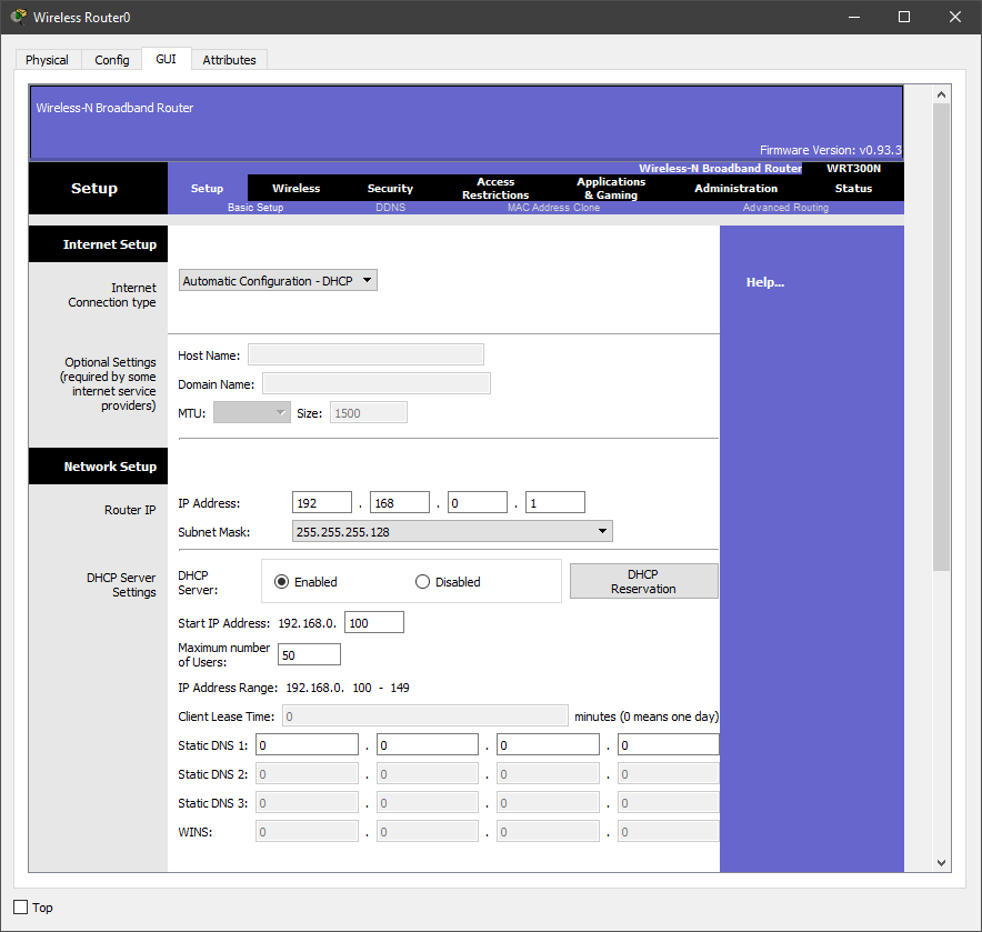
5. Set up a wireless router (Wireless Router0) to work with the network. To do this, as in the case of the previous router, go to the settings of the router by double clicking on it. In the tabs, select the graphical user interface (GUI - graphical user interface). This mode will be displayed when entering the router's address in any browser.
Set the following settings:
Internet Connection Type – Static IP
Internet IP Address – 120.120.0.2
Subnet Mask – 255.255.255.0
Default Gateway – 120.120.0.1
Router IP – 192.168.0.1
Subnet Mask (Router IP) – 255.255.255.0
Start IP Address – 192.168.0.100
Maximum numbers of Users – 50
And at the bottom of the page press the button "Save settings"
Parsing settings:
We chose a static IP, since the provider gave us a white IP address (120.120.0.1/24). The default path (Default Gateway) is the address of the router from the provider. The address of the router from the wireless devices - 192.168.0.1/24. The router will distribute IP from 100 to 150.
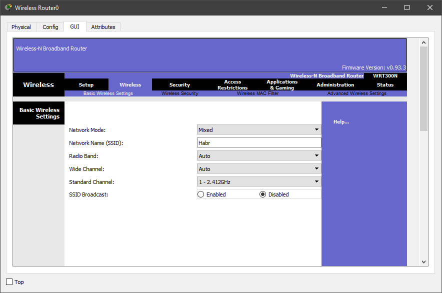
6. Go to the Wireless tab, that is, the wireless connection.
We set the following settings:
Network Mode – Mixed
Network Name (SSID) – Habr
Radio Band – Auto
Wide Channel – Auto
Standard Channel – 1 – 2.412GHz
SSID Broadcast – Disabled
And at the bottom of the page press the button "Save settings"
Parsing settings:
We chose a mixed mode of the router, that is, any device that supports router types can connect to it (in the Cisco Packer Tracer emulator, these are g, b, and n). The name of the network we put Habr. The router will choose the channel width itself (it is possible to choose either 20 or 40 megahertz). The frequency in the emulator is available only 2.4GHz and we will leave it. We hid the network name, that is, the devices will not see our Wi-Fi network until they introduce its name.
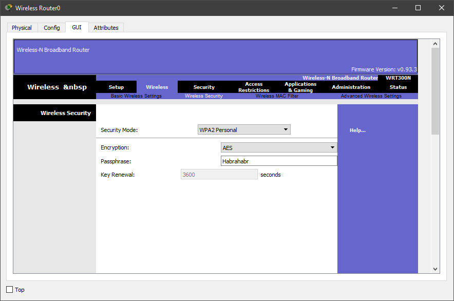
7. Set up the protection of our router. To do this, go to the Security tab and in the “Security Mode” section, select WPA2 Personal, because WPA is a vulnerable protection. There is no need to choose WPA2 Enterprise either, since for her work we need a radius server, which we did not do. The encryption algorithm is left AES and enter the code word. I set Habrahabr.
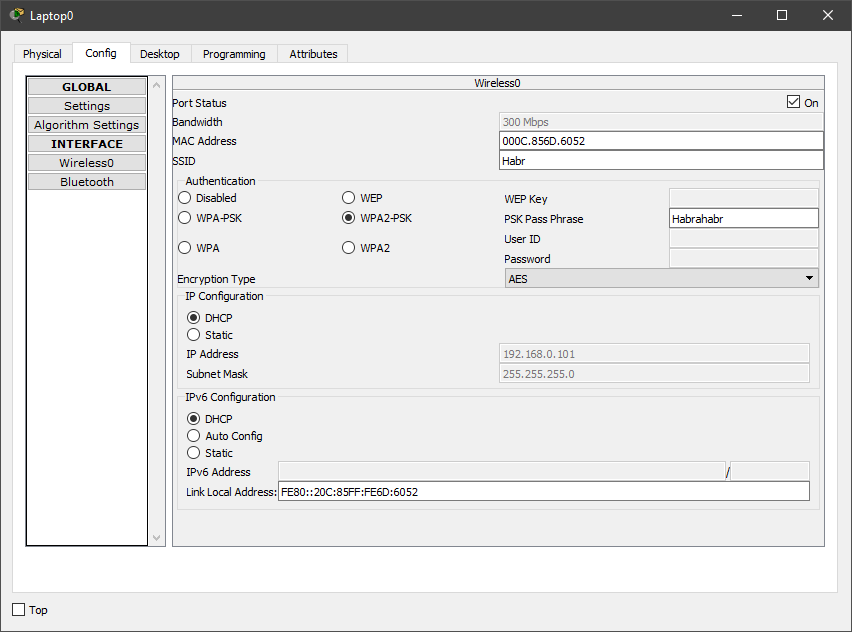
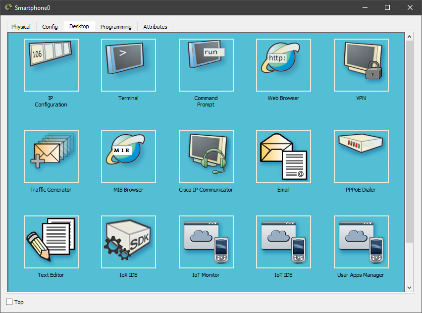
8. Add 3 devices, as in the diagram (smartphone, laptop and computer). Then replace the connectors for rj-45 to a Wi-Fi antenna (in the smartphone, the default antenna).
9. In the Config tab, set the settings that were set on the router. This operation must be done on all devices.
10. Go to the desktop of any computer and open the command line.
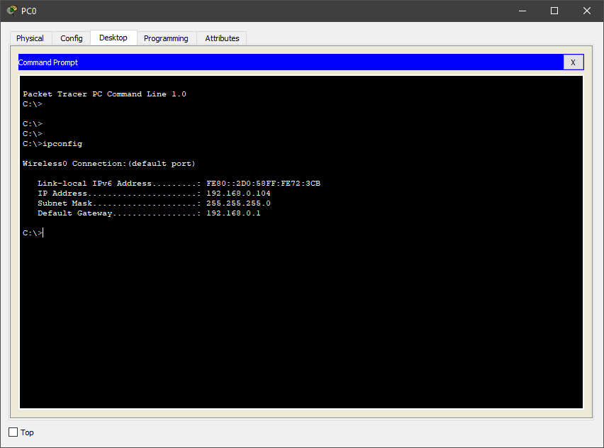
11. Check what addresses the router issued devices. To do this, enter the command ipconfig.
As can be seen in the screenshot, the router gives addresses from 192.168.0.100 to 192.168.0.150.
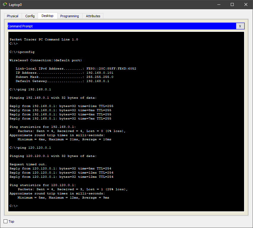
12. We check the network operability from any device using the ping command. We will ping 2 addresses - the address of the router (192.168.0.1) and the white address (120.120.0.1), that is, we will check if the device can access the Internet.
Again, everything works.
As a result, we got a Wi-Fi network, which is shown in the second use case.
Task number 1 (option network number 3)
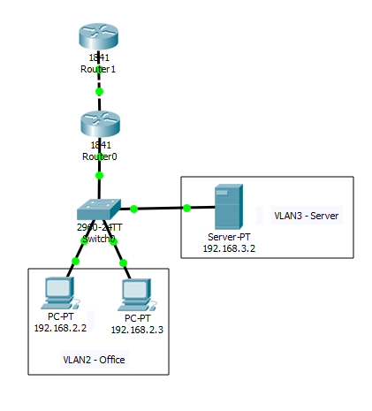
1. Open the finished project from the previous PAT laboratory work .
2. Create an access point on the working area of the program and connect it to the switch. If desired, the access point can be configured (Port 0 is a physical port, and Port 1 is a wireless)
3. Create another VLAN for a wireless access point.
4. Add in the settings of the router 0 VLAN 4, and also add it to the access list to access the Internet.
Since we did this in previous labs (on VLAN and PAT ), I will not dwell in detail, but I will register all the commands on the devices
Switch
Switch>en
Switch#conf t
Switch(config)#vlan 4
Switch(config-vlan)#name Wi-Fi
Switch(config-vlan)#exit
Switch(config)#interface FastEthernet0/5
Switch(config-if)#switchport access vlan 4
Router (subinterface)
Router>en
Router#conf t
Router(config)#int fa0/1.4
Router(config-subif)#encapsulation dot1Q 4
Router(config-subif)#ip address 192.168.4.1 255.255.255.0
Router(config-subif)#no shutdown
Router(config-subif)#end
Router (DHCP (Dynamic Host Configuration Protocol - Dynamic Host Configuration Protocol). A network protocol that allows computers to automatically obtain an IP address and other parameters necessary for work on a TCP / IP network)
Router#conf t
Router(config)#ip dhcp pool Wi-Fi-pool
Router(dhcp-config)#network 192.168.4.0 255.255.255.0
Router(dhcp-config)#default-router 192.168.4.1
Router(dhcp-config)#exit
Router(config)#ip dhcp excluded-address 192.168.4.1
Router(config)#end
I’ll stop here in more detail, since we haven’t previously met with this parameter.
Router (config) #ip dhcp pool Wi-Fi-pool - creating a pool (set) of dhcp addresses
Router (dhcp-config) #network 192.168.4.0 255.255.255.0 - the network in which dhcp is implemented and its mask
Router (dhcp-config) # default-router 192.168.4.1 - default address (the same as the router's address)
Router (config) #ip dhcp excluded-address 192.168.4.1 - exclusion of the router's address from the distribution via dhcp
Router (access list)
Router(config)#ip access-list standard HABRAHABR
Router(config-std-nacl)#permit 192.168.4.0 0.0.0.255
Router(config-std-nacl)#exit
Router(config)#int fa0/1.4
Router(config-subif)#ip nat inside
Router(config-subif)#end
Add a smartphone to the Packet Tracer workspace and ping the PC, server and Internet, that is, 192.168.2.2, 192.168.3.2, 120.120.53.1.
As you can see, everything works.
Task number 2 (option network number 1)
Unfortunately, in Packet Tracer there is no possibility to create a Wi-Fi bridge (also known as a repeater or repeater), but we will do this simple operation on real hardware in a graphical environment.
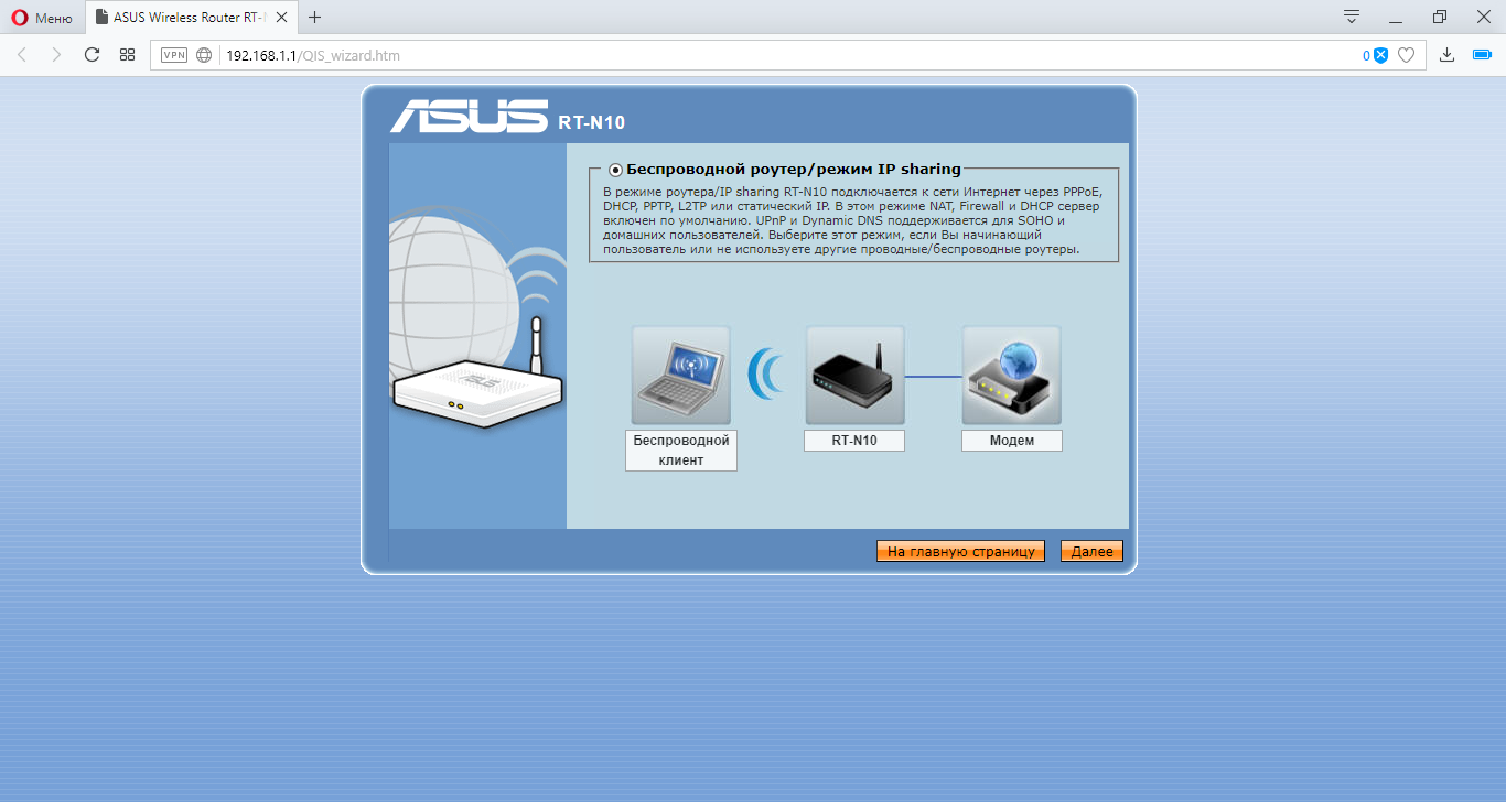
The equipment on which the settings will be made is the ASUS RT-N10 router and the so-called TP-LINK TL-WA850RE repeater.
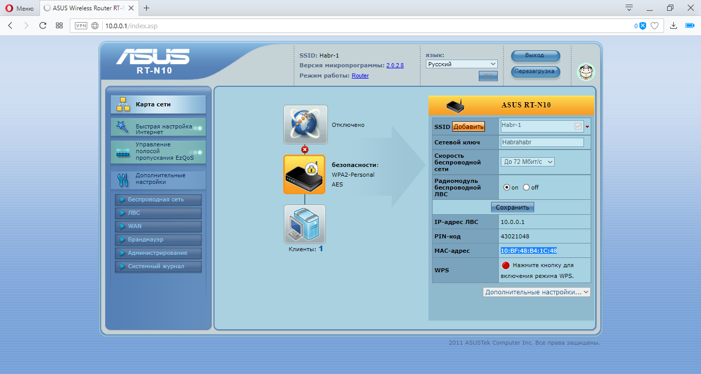
Let's proceed to the configuration of the Asus router. To do this, open the browser and enter the address of the router (by default it will open itself)
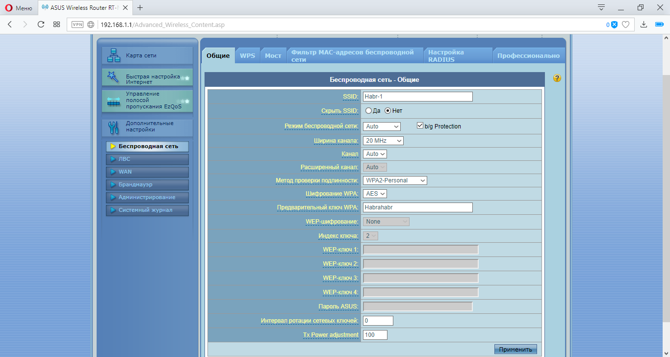
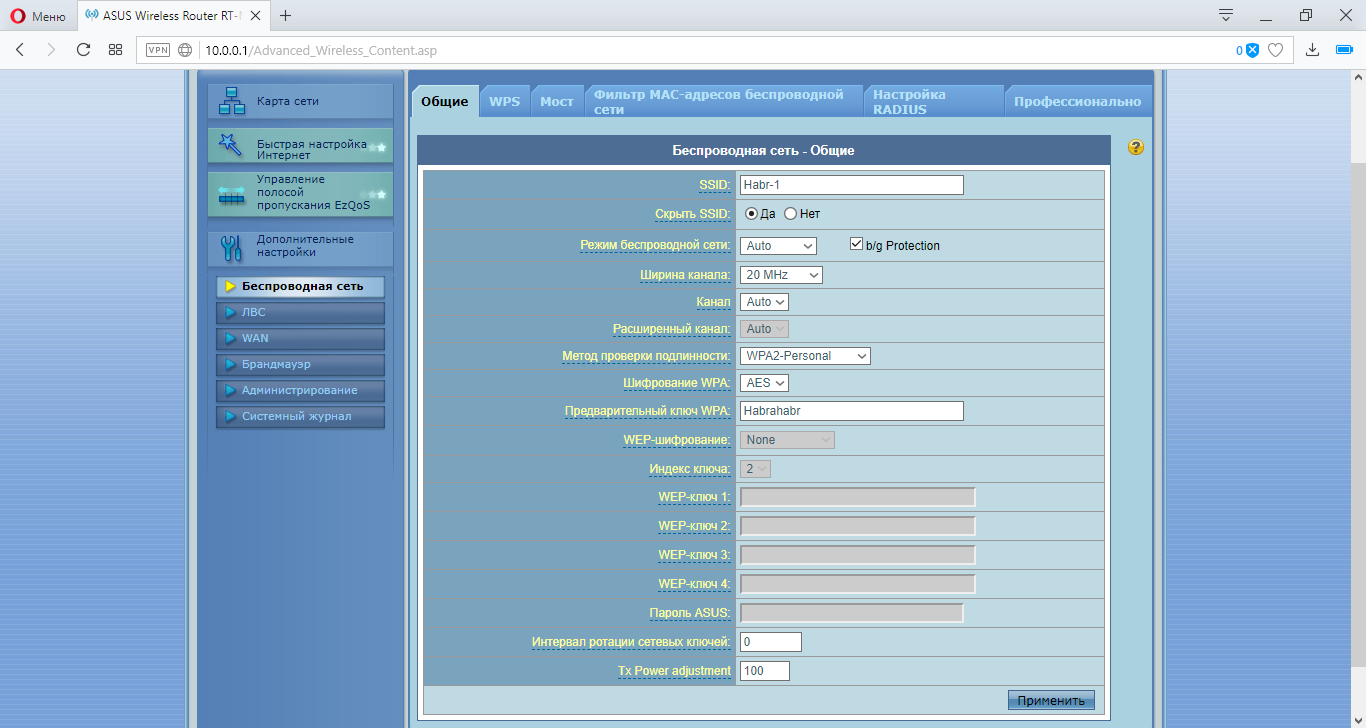
Go to the tab "Wireless Network" and set the setting as in the screenshot below.
Go to the tab "LAN" (local area network) and set the following settings.
Go to the main tab. There we can see our MAC address
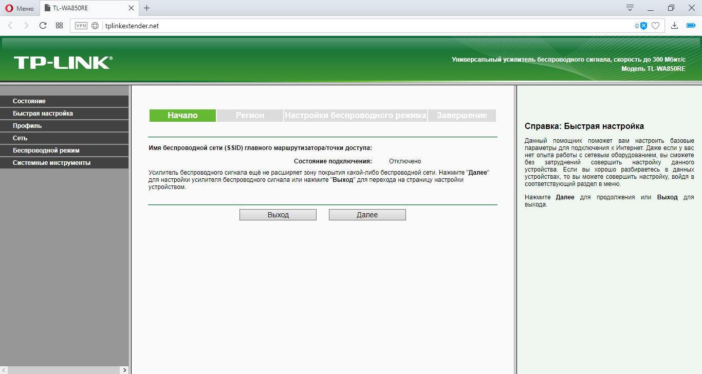
Go to setting up the TP-LINK repeater
We automatically device will give the main menu and quick setting mode. Click "Exit" and perform the settings themselves.
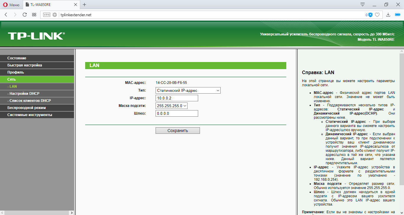
Go to the tab "Network" and set the following settings.
Go to the tab "Wireless Mode" and configure the input and output stream.
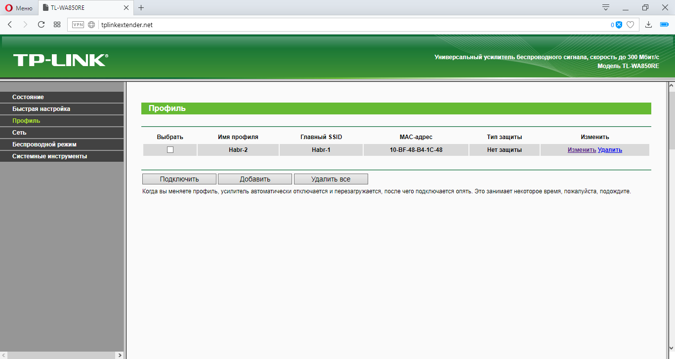
In the "Profile" tab, we see all the profiles we created. Click the button "Change"
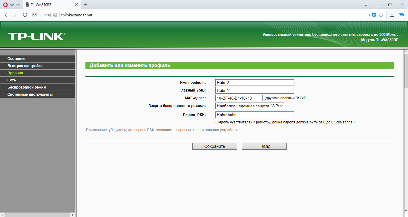
Configure output network security by adding a WPA2 key.
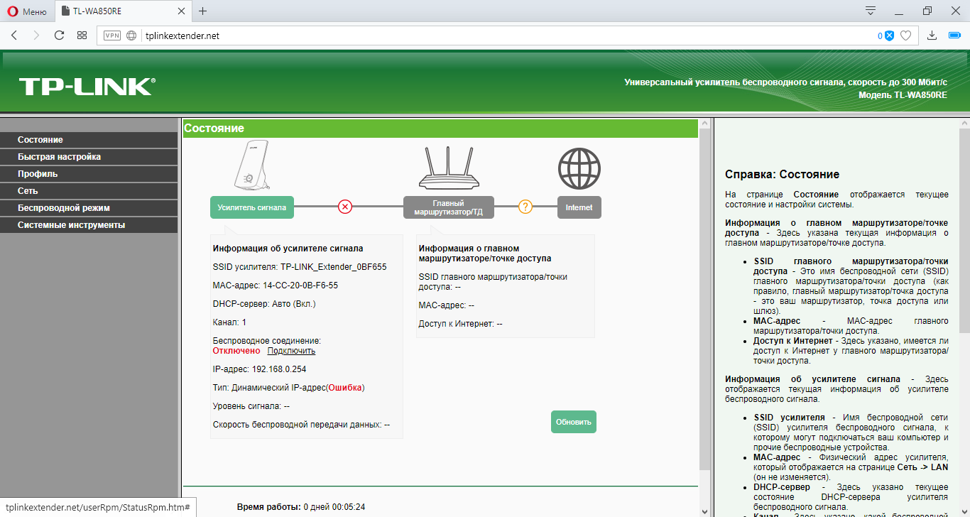
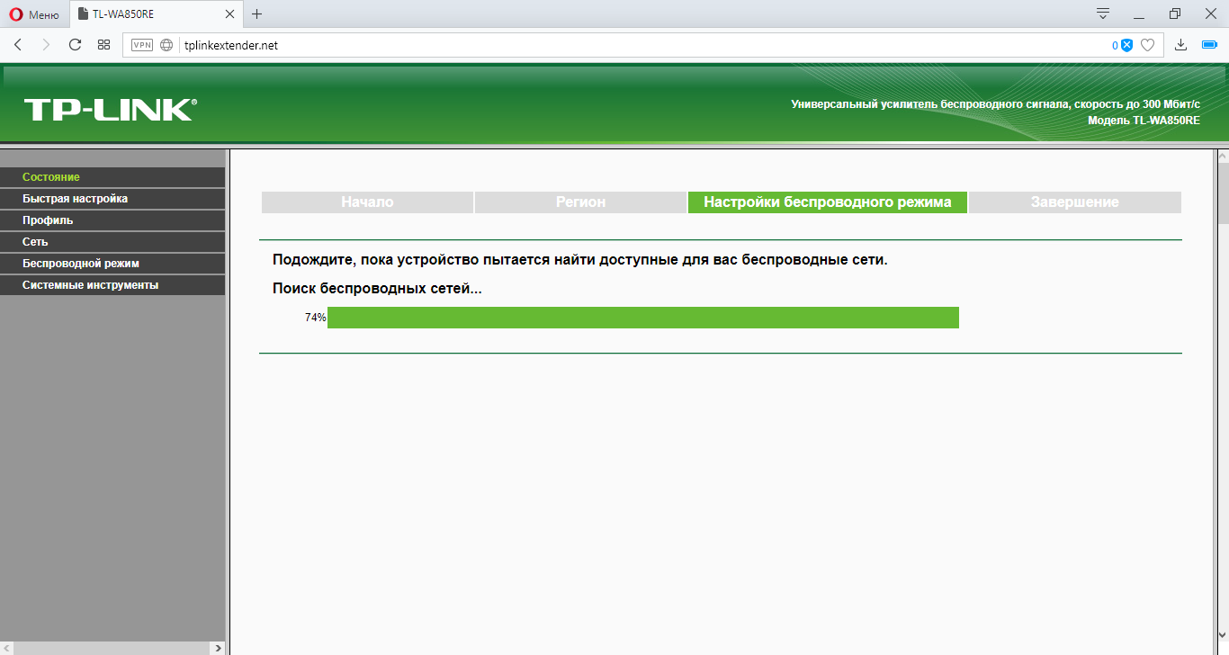
Go to the main menu and select the item "Connect" in the "Wireless Connection". Next will configure the bridge. It may be necessary to enter a password from an Asus router.
After clicking the button will load the configurations
And voila! All is ready!
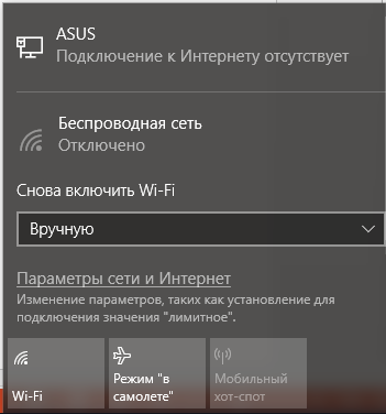
In order not to be confused to which device to connect, you can hide the SSID on the Asus router
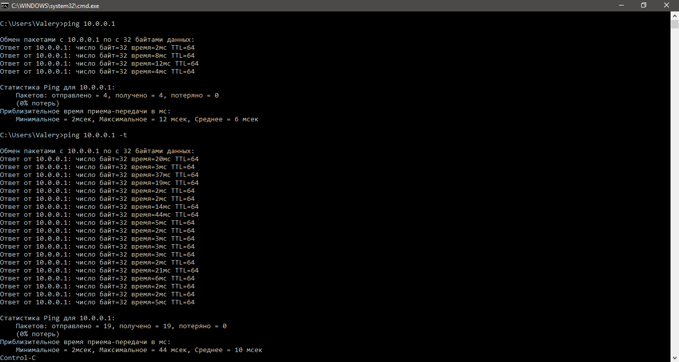
We check the connection by cable
Ping is successful.
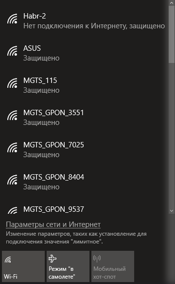
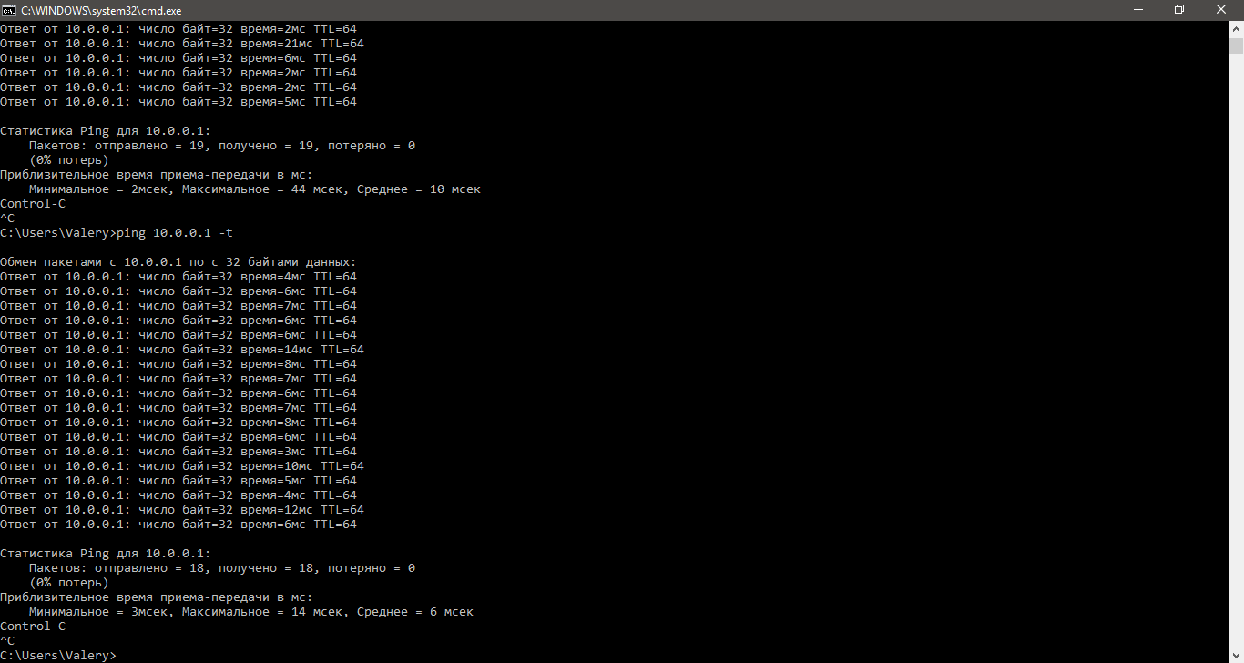
Check on Wi-Fi.
Successfully.
And review the final configuration, when connected to the repeater.
Source: https://habr.com/ru/post/351564/
All Articles