KOMPAS-3D Home - professional CAD software for home and hobby
If I had told the management a couple of years ago that users of the home version of KOMPAS-3D — lovers of engineering 3D-modeling, were sitting at Habré — they would have laughed at me. But every year the sphere of design and IT grows together more and more, and the interest in 3D printing makes IT people study CAD systems more closely. Perhaps that is why one of the first comments to our articles were questions about KOMPAS-3D Home. This inspired me to write this article, I will try to answer in it the main questions of users. Moreover, KOMPAS-3D v17 Home is finally fully released. Although this year, due to negotiations with retail chains, the edition of the boxed version has been somewhat delayed. The article will try to answer the basic questions of users.
The article turned out to be large-scale, I recommend to watch from a computer or from a mobile device with a stable wifi. For readability, all the details are removed in spoilers. For those who know KOMPAS, it will be convenient to read a short article about new products, and for those who want to study the product better, welcome to spoilers, there is a whole manual on the product and three lessons on three main types of modeling.

Vehicles for movement in space - author Kekova Anastasia
')
CAUTION, TRAFFIC!
KOMPAS-3D v17 Home allows you to:
KOMPAS-3D v17 Home:
The trial version allows you to work for free for 60 days, the full version costs 1490 rubles (for an annual license).
With KOMPAS-3D v17 Home you get the functionality of a professional CAD system. You can create an object of any complexity. If industrial enterprises create almost any of their projects, then you definitely will not encounter any difficulties in your personal projects.
Specialized machine MOE

Developer: Titan-Barricades Federal Research and Production Center, Volgograd
In KOMPAS-3D v17 Home there is a full-fledged API and SDK.
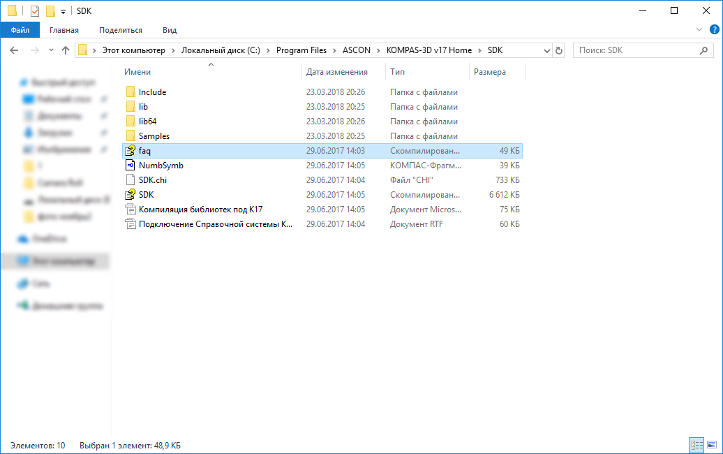
You can write applications for KOMPAS-3D v17 Home in various programming languages (C ++, C #, Delphi, Python, VB, etc.).
In addition, using the KOMPAS-Macro application, you can write macros in Python, even without programming experience.
The product becomes quality when you want to work in it yourself. Even the very first versions of KOMPAS were used both by ASCON employees and users for personal purposes: to arrange furniture, to calculate the number of tiles, the wallpaper footage, to make a project of a country house, etc. Users took for this purpose trimmed LT versions and pirated products. In 2011, we decided to conduct an experiment and released a version without reducing any functionality (with all our libraries and applications) at a price affordable to any user. None of the world's manufacturers of professional three-dimensional CAD systems did this at the time. The product found its user. Like the product and our staff.
Askonovtsy - people are very versatile and in their free time engaged in various hobbies and sports. For example, Dmitry Fedin, an implementation engineer from ASCON-Tula, is keen on airsoft. He made an assault shield in KOMPAS-3D Home.
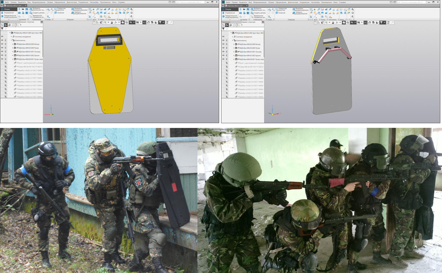
An assault shield for airsoft (a copy of the VANT-VM shield). By Dmitry Fedin (clickable image)
Not only ordinary employees, but also the ASCON management uses KOMPAS-3D Home. Sergey Evsikov, director of ASCON-Systems Design, made a unique dial for his watches.

Dial for wristwatches. Author Sergey Evsikov (the picture is clickable)
At the time of the appearance of KOMPAS-3D Home, the home CAD market was 100% pirated. The blocking of torrents does not work even now, and then no one thought to block them. We decided to give law-abiding users the opportunity to purchase the product completely legally, and in the first year, many took advantage of this opportunity. Even then, on a fully pirated market and without blocking torrents and other things. Every year the product becomes more popular and gains new users.

The project of improvement of the local area. Author Mikhail Pankov
The same type of team combined into groups. Inside the groups, the parameters of the command are saved to the maximum. Commands within a group can be switched at the top of the Options panel or selected from the drop-down panel that appears if you hold down the left mouse button on the main command in the toolbar.
The most frequently used modes and settings are in a separate menu.
The settings panel is designed to manage the settings of the command.

To work with applications and libraries there is a configurator, which is in the application menu.
After the call, the configurator window opens.

The new version has several types of search.
Team Search
Located in the upper right corner of the screen. Allows you to find the command you need by name.
Search in the tree
Located at the top of the document tree. Allows you to find an operation or component in the tree. Tree search features complete the filters.
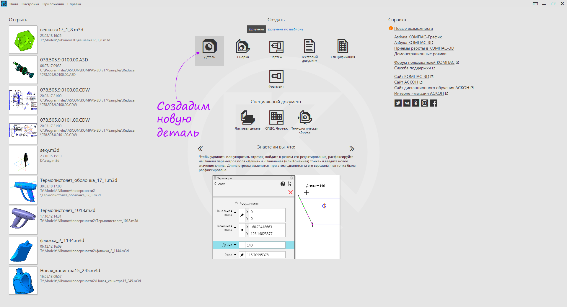
The first thing you see when starting the program is the start page. From there, you can create a new document, open an existing one, purchase and activate a license, start exploring the program with the help of educational materials and navigate to KOMPAS-3D websites and social networks to communicate and exchange experience with like-minded people.

The activation utility is needed to obtain a license.


( )

, — , , .


, .

.

, .

.
-

, .

-3D , .

, -3D , , .

, , , . -3D, , , . .

( )
, , , .

, , , , . .
, .
, . . , , . , .
, .
, .
, , , .. .
, .

, .
, . , , , , . , , . , .
, .
, .
. .
.
.

, .

, , .

, .
, , .
.

, .
, .
, .
/
, .

, .
.
.
.

, .
.

, .
, .

, .

.

, .

, .

( ).

, , .

, .

.

.
.

.

, , .
( ).

.
.

.

. .
.
-

- .

.

.

.

. , , .
/

, . , , .

, .

.

.

.
, .

.

.
.

.

-.
.

17 — , , .

( ).

, .

.

.
, .

.

.

, , . .

.

.

, .

, .
.
.

.

.

- .

, .

.
.

- , .

- , .
.

...

.

, .

.
.
...

.

, , .
/
/ , .
, .

.
, , .

, « -3D». « -3D» 17 .

.

. , .
« -3D»
« -3D»

, .

.
/

.

.


, , .
.


( ).

, ,

( )

. , .. . .

( )

, . , .

.

.

. .

( )
. , . , .
.

— , , — .
, . , .


.
( )

. ( )


( )
( )

3D- ,
-3D , «». « -», « -3D» « ».

-3D Home « 3D-», , 3D-.

Here are three small construction lessons on the main types of modeling. Lessons do not intersect with the ABC, so it will be a good addition to them.

.
 , -3D Home
The article turned out to be large-scale, I recommend to watch from a computer or from a mobile device with a stable wifi. For readability, all the details are removed in spoilers. For those who know KOMPAS, it will be convenient to read a short article about new products, and for those who want to study the product better, welcome to spoilers, there is a whole manual on the product and three lessons on three main types of modeling.
Vehicles for movement in space - author Kekova Anastasia
')
CAUTION, TRAFFIC!
Spoilers turned out to be quite extensive, so their structure may seem a bit confusing, if you don’t read everything. For convenience of orientation at the end of the spoiler added information that the spoiler is over. If you see the inscription "End ...", then the spoiler can be closed and continue reading the text outside the spoiler.
Basic functionality
KOMPAS-3D v17 Home allows you to:
- create models;
- create drawings;
- assemble assemblies from individual parts using mates, as well as animate them;
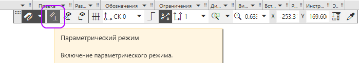
- parameterize models and drawings;
- create and edit files of exchange data formats DXF, DWG, Step, Sat, IGES;
- create and edit files with STL facet format.
KOMPAS-3D v17 Home:
- equipped with a new modern interface - about it separately below. You can also read an article about its design: one , two ;
- has a restriction on commercial use;
- presented in two versions - x86 and x64.
The trial version allows you to work for free for 60 days, the full version costs 1490 rubles (for an annual license).
The program features complement various applications.
Standard Products - allows you to add ready-made hardware, bearings and other elements to the product.
Materials and grades - allows you to use ready-made materials.
Shafts and mechanical gears - allows you to build gears and gear wheels.
Mechanics: Springs - allows you to calculate and add to the product ready-made springs.
Equipment: Metal - allows you to design all kinds of frames and frames of the profile metal.
Equipment: Pipelines - allows you to design various engineering communications.
Mechanics: Animation - allows you to create moving assemblies and record videos.
3D model recognition - allows you to turn imported models into editable ones.
There is also a group of building libraries:
Full list of applications KOMPAS-3D v17 Home
End of application description
Functional professional CAD
With KOMPAS-3D v17 Home you get the functionality of a professional CAD system. You can create an object of any complexity. If industrial enterprises create almost any of their projects, then you definitely will not encounter any difficulties in your personal projects.
Specialized machine MOE
Developer: Titan-Barricades Federal Research and Production Center, Volgograd
Other examples
Machine SBSH - 250MNA - 32 for those. task "Stoilensky GOK"

Developer: “UK-Rudgormash-Voronezh”
Small-sized block separation and bulk plant (MBSNU)

Developer: Uraltechnostroy Corporation, Ufa
Gamma-therapeutic device Rocusus-R

Developer: Equality, St. Petersburg
Fire ladder AL - 30 (43502) P

Developer: Fire Systems, Tver
Multi-storey residential building

Developer: Severnoe Machine-Building Enterprise Production Association (SEVMASH), Severodvinsk
The packer of rolls in a polymeric sleeve "UPR-1"
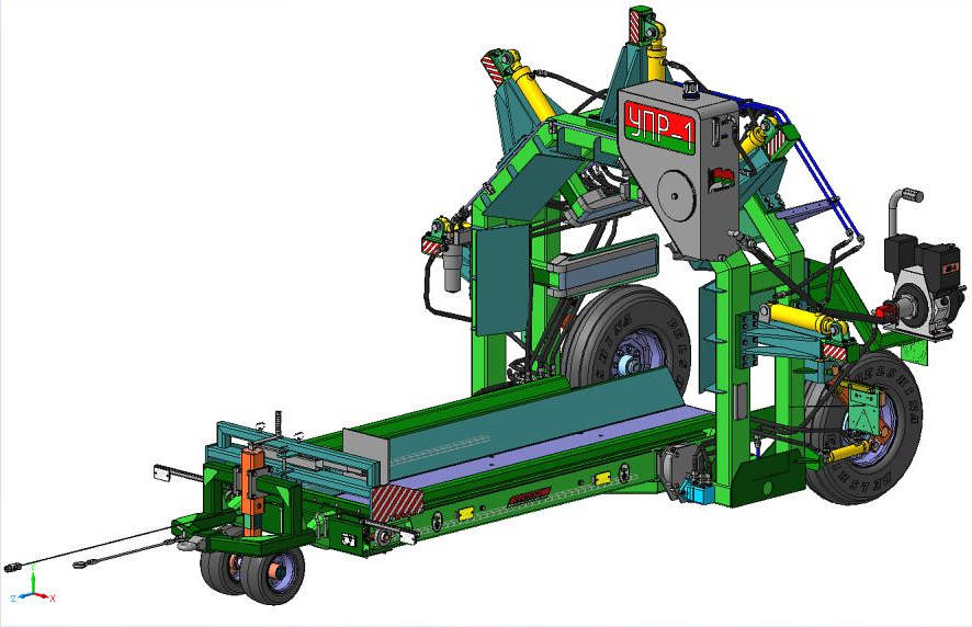
Developer: Bobruiskagromash, Bobruisk
Developer: “UK-Rudgormash-Voronezh”
Small-sized block separation and bulk plant (MBSNU)
Developer: Uraltechnostroy Corporation, Ufa
Gamma-therapeutic device Rocusus-R
Developer: Equality, St. Petersburg
Fire ladder AL - 30 (43502) P
Developer: Fire Systems, Tver
Multi-storey residential building
Developer: Severnoe Machine-Building Enterprise Production Association (SEVMASH), Severodvinsk
The packer of rolls in a polymeric sleeve "UPR-1"
Developer: Bobruiskagromash, Bobruisk
You can see these and other examples on the page of our 3D Aces Competition.
End of examples listing
Ability to extend the functionality through the API. Sdk
In KOMPAS-3D v17 Home there is a full-fledged API and SDK.
You can write applications for KOMPAS-3D v17 Home in various programming languages (C ++, C #, Delphi, Python, VB, etc.).
By the way, applications created under KOMPAS-3D v17 Home will work in the professional version.
In addition, using the KOMPAS-Macro application, you can write macros in Python, even without programming experience.
Where can I find more information?
History of the project KOMPAS-3D Home
Themselves used for their projects
The product becomes quality when you want to work in it yourself. Even the very first versions of KOMPAS were used both by ASCON employees and users for personal purposes: to arrange furniture, to calculate the number of tiles, the wallpaper footage, to make a project of a country house, etc. Users took for this purpose trimmed LT versions and pirated products. In 2011, we decided to conduct an experiment and released a version without reducing any functionality (with all our libraries and applications) at a price affordable to any user. None of the world's manufacturers of professional three-dimensional CAD systems did this at the time. The product found its user. Like the product and our staff.
Askonovtsy - people are very versatile and in their free time engaged in various hobbies and sports. For example, Dmitry Fedin, an implementation engineer from ASCON-Tula, is keen on airsoft. He made an assault shield in KOMPAS-3D Home.
An assault shield for airsoft (a copy of the VANT-VM shield). By Dmitry Fedin (clickable image)
Not only ordinary employees, but also the ASCON management uses KOMPAS-3D Home. Sergey Evsikov, director of ASCON-Systems Design, made a unique dial for his watches.
Dial for wristwatches. Author Sergey Evsikov (the picture is clickable)
Other interesting projects of ASCON employees
Dmitry Krekin, marketing manager of ASCON machine building, designed in COMPAS and made himself a simple simulator in the form of a bench with a variable back angle.
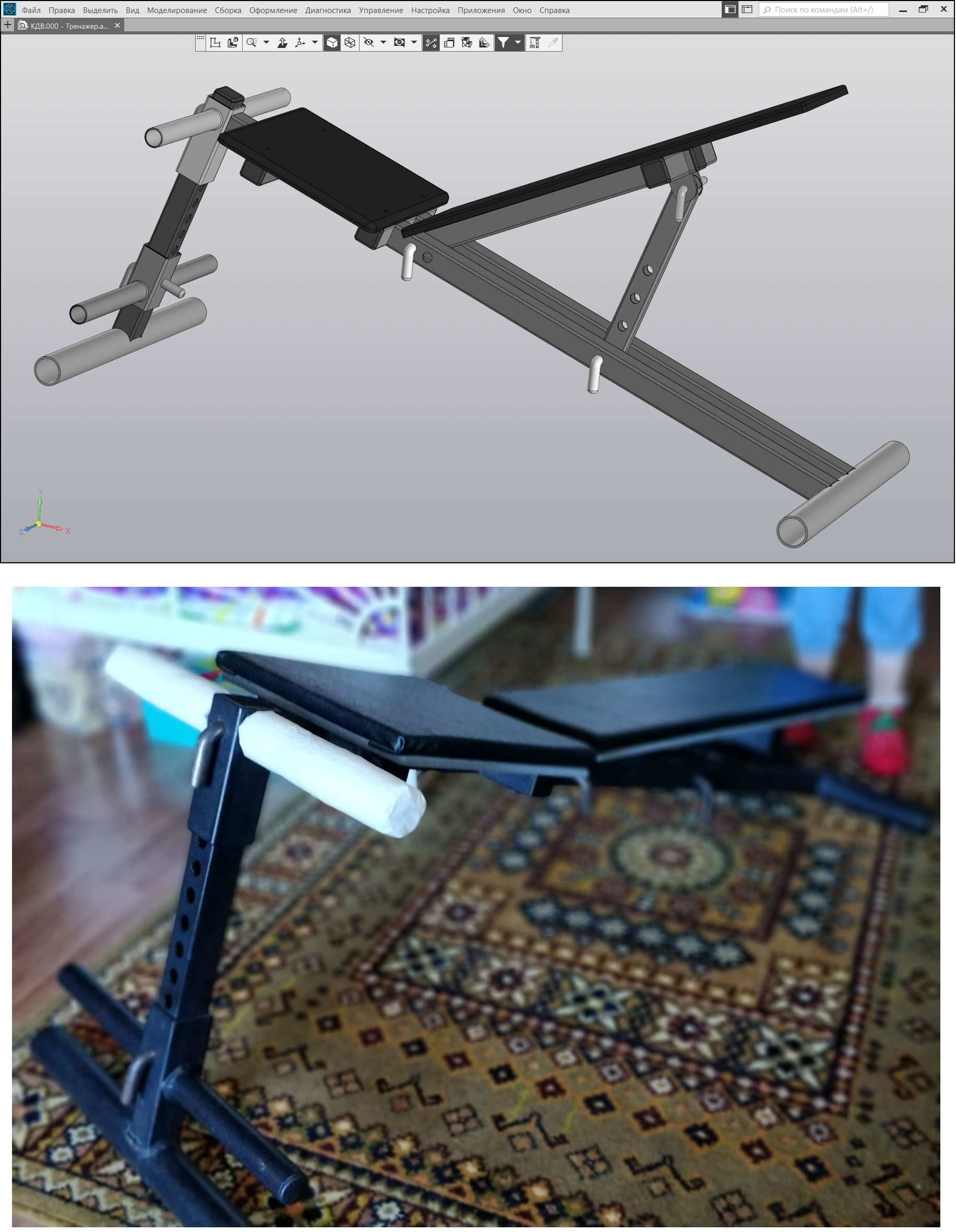
Simulator bench. Author Dmitry Krekin (clickable image)
Victor Doin, testing engineer from ASCON-Kolomna, designed the frame of a 2-storey panel house using the “Hardware: Metal” application, which is part of KOMPAS-3D Home.
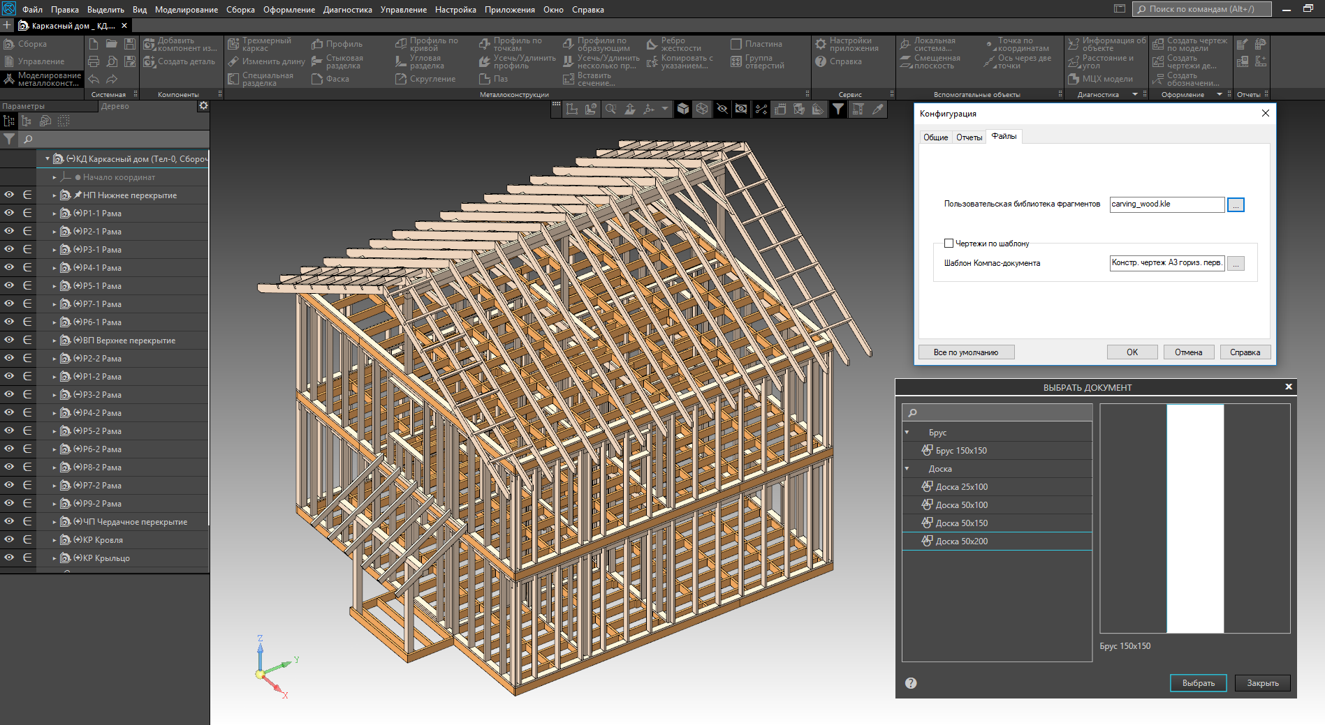
The frame of a two-story house. The author Victor Doin (picture clickable)
Prior to this, Victor designed in COMPAS and built a fence and gate.

Fence and gate. The author Victor Doin (picture clickable)
The wooden house behind this fence was also designed by Viktor in COMPASS. It remains to finish only the designed extension.
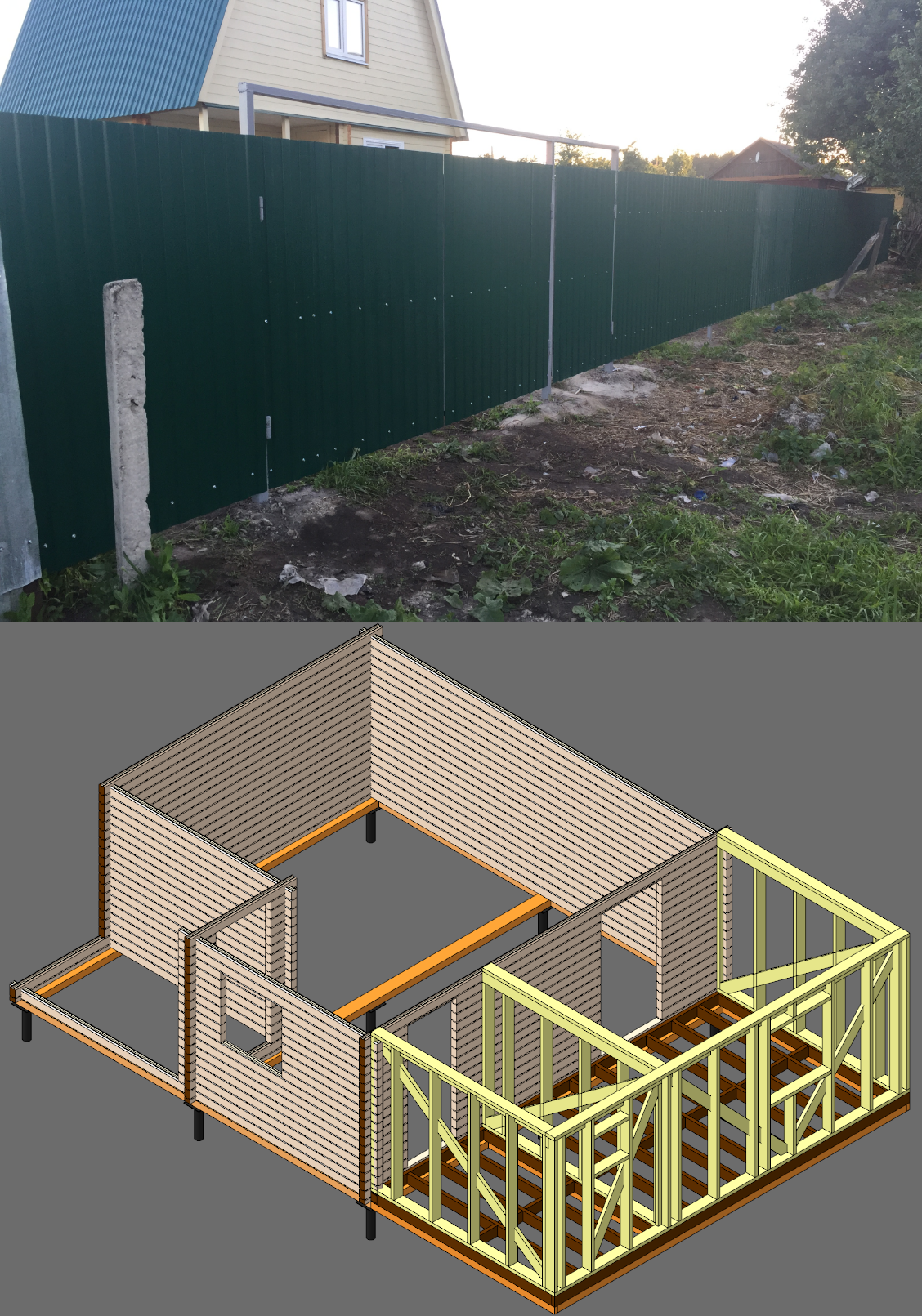
House and fence. The author Victor Doin (picture clickable)
Alexander Yazykov, sales and implementation manager for CAD / CPP / PLM from ASCON-Ryazan, designed and made the swing for the dacha using the “Hardware: Metal Structures” application.

Swing. Author Alexander Yazykov (the image is clickable)
Recently, Alexander had a car phone holder broken - he modeled a replacement for a broken part in KOMPAS-3D and made it on a 3D printer in a local printing shop.
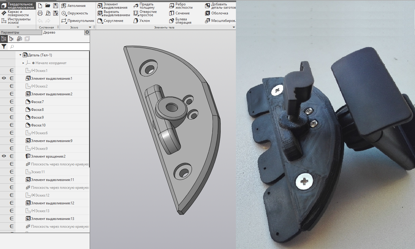
Car phone holder. Author Alexander Yazykov (the image is clickable)
Ilya Teterin, an OPP analyst on the implementation of the SAUP GOLFSTRIM from ASCON-North-West, has used KOMPAS fragments for working with origami schemes for many years. Both for the development of their schemes, and for the analysis of ready (for typical angles, integer divisions of the parties, etc.).

Origam scheme. Author Ilya Teterin (image is clickable)
Irina Sidorova, head of a group of technical writers from ASCON-Kolomna, with the help of KOMPAS, divided the plan of her apartment into sectors around the world, in order to choose colors in the interior according to feng shui.

Apartment plan according to feng shui. Posted by Irina Sidorova (clickable image)
Viktor Ivanov, a teacher and implementation engineer from ASCON-Kurgan, designed a desk at KOMPAS for working at a laptop while standing.
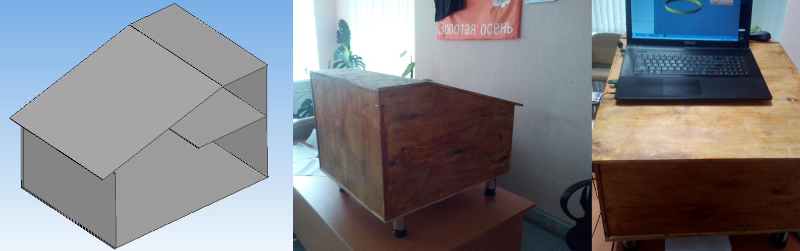
Desk for laptop. The author Viktor Ivanov (picture clickable)
Dmitry Fedin, an implementation engineer from ASCON-Tula, has other jobs besides the shield. For example, a model of a body kit and a silencer for an airsoft copy of a GLOCK 17 pistol.
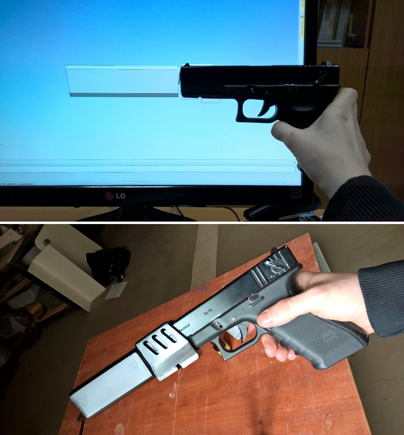
Body kit and silencer GLOCK 17. By Dmitry Fedin (clickable image)
For the form of his airsoft team, Dmitry modeled a chevron mock-up in KOMPAS. Chevron was made in different colors and used by all the fighters of the team.
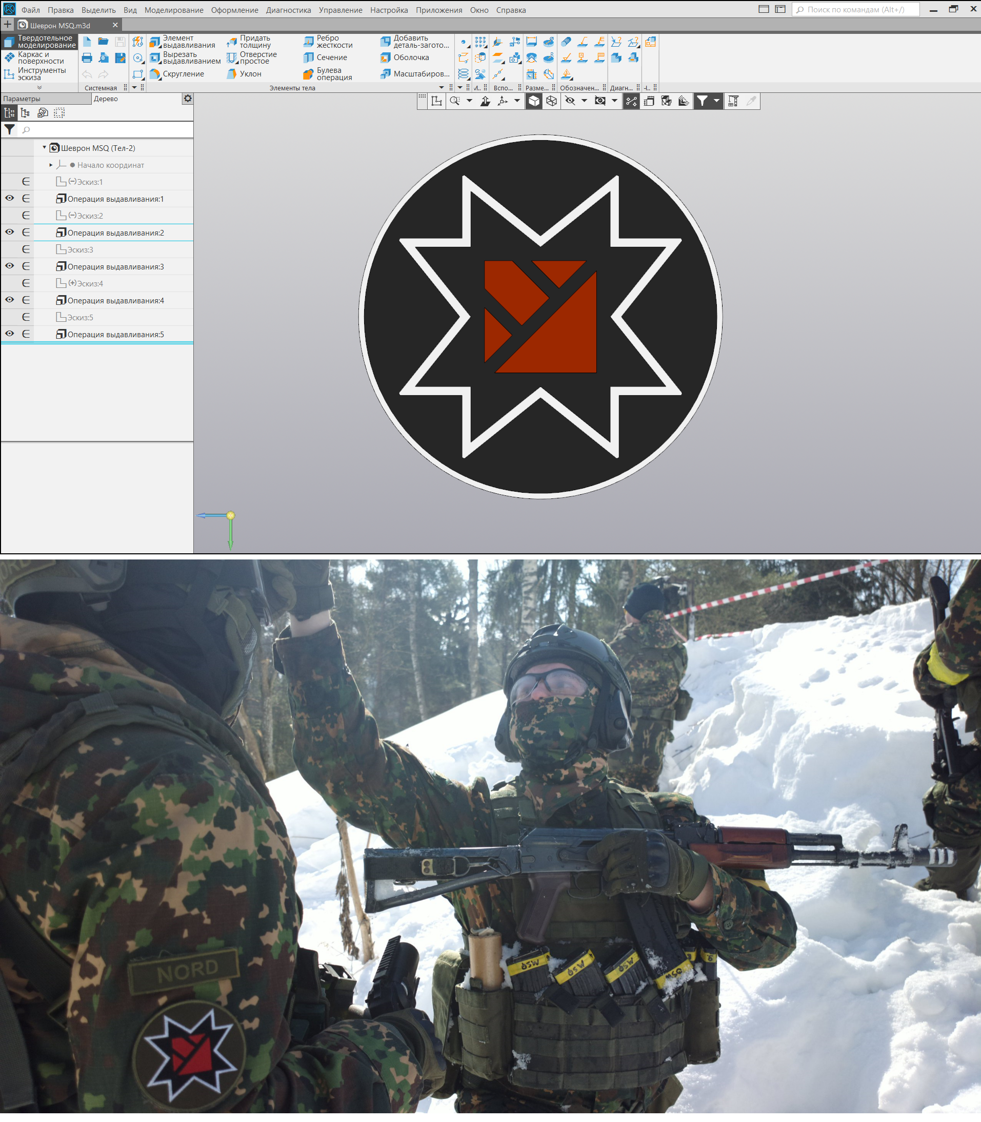
Chevron. By Dmitry Fedin (clickable image)
In addition to airsoft, Dmitry enjoys making mockups. This layout of the BMP-2M "Berezhok" was designed in KOMPAS, then the parts were made on the CNC, and then assembled and painted by hand.

BMP-2M "Berezhok". By Dmitry Fedin (clickable image)
Dmitry's passion for mock-ups allowed him to take part in the charity project of the All-Russian Society of the Blind. Within the framework of the project, it was intended to make a layout of places significant for Tula in order to show them to blind and visually impaired children.
Here is how Dmitry describes the work within the project:

Models for making the layout of the Tula Kremlin (the picture is clickable)
A model of the Tula Kremlin created within the project was installed in the museum of the All-Russian Society of the Blind.
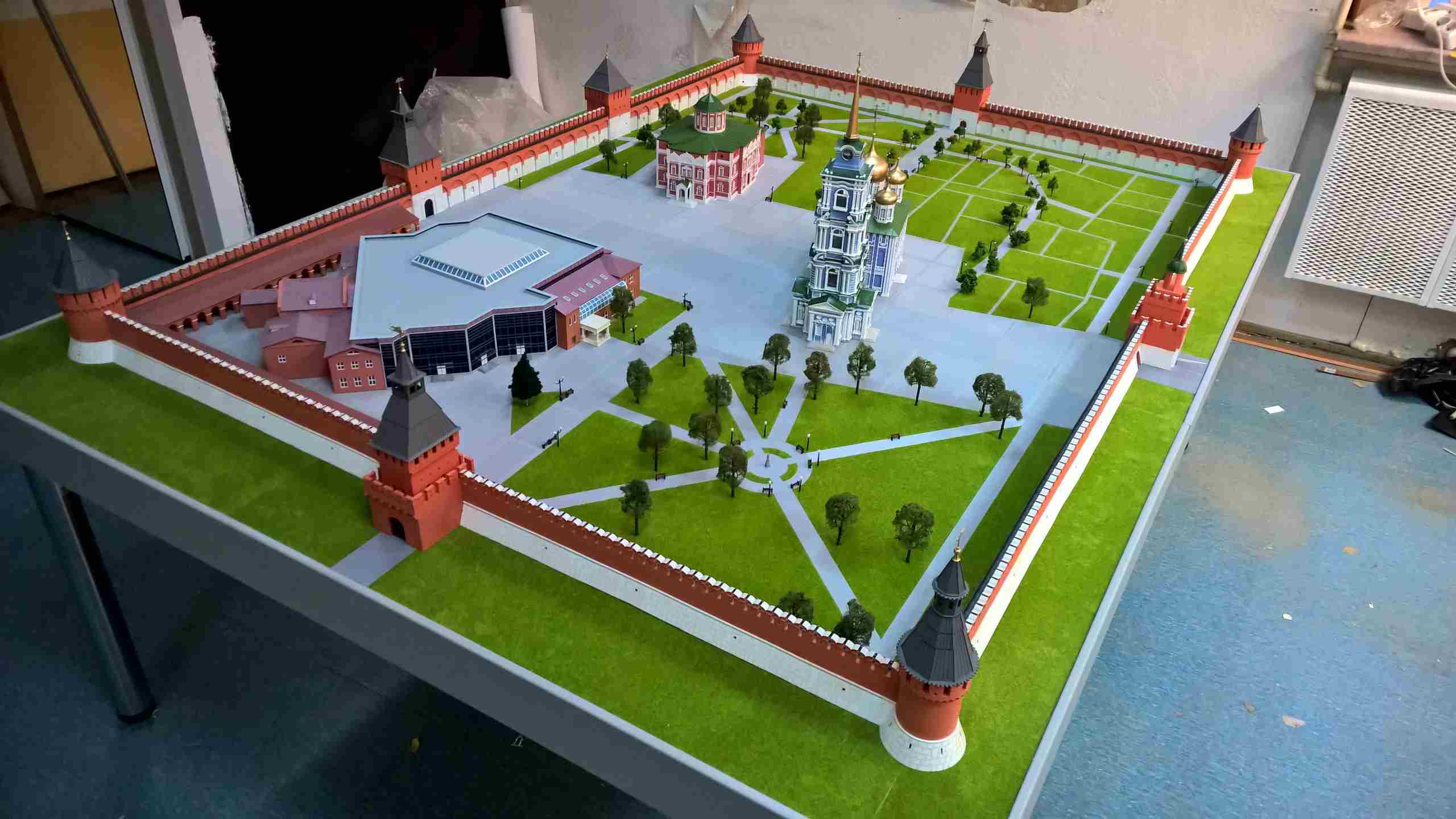
Ready-made layout of the Tula Kremlin in the Museum of the All-Russian Society of the Blind (the picture is clickable)
Simulator bench. Author Dmitry Krekin (clickable image)
Victor Doin, testing engineer from ASCON-Kolomna, designed the frame of a 2-storey panel house using the “Hardware: Metal” application, which is part of KOMPAS-3D Home.
The frame of a two-story house. The author Victor Doin (picture clickable)
Prior to this, Victor designed in COMPAS and built a fence and gate.
Fence and gate. The author Victor Doin (picture clickable)
The wooden house behind this fence was also designed by Viktor in COMPASS. It remains to finish only the designed extension.
House and fence. The author Victor Doin (picture clickable)
Alexander Yazykov, sales and implementation manager for CAD / CPP / PLM from ASCON-Ryazan, designed and made the swing for the dacha using the “Hardware: Metal Structures” application.
Swing. Author Alexander Yazykov (the image is clickable)
Recently, Alexander had a car phone holder broken - he modeled a replacement for a broken part in KOMPAS-3D and made it on a 3D printer in a local printing shop.
Car phone holder. Author Alexander Yazykov (the image is clickable)
Ilya Teterin, an OPP analyst on the implementation of the SAUP GOLFSTRIM from ASCON-North-West, has used KOMPAS fragments for working with origami schemes for many years. Both for the development of their schemes, and for the analysis of ready (for typical angles, integer divisions of the parties, etc.).
Origam scheme. Author Ilya Teterin (image is clickable)
Irina Sidorova, head of a group of technical writers from ASCON-Kolomna, with the help of KOMPAS, divided the plan of her apartment into sectors around the world, in order to choose colors in the interior according to feng shui.
Apartment plan according to feng shui. Posted by Irina Sidorova (clickable image)
Viktor Ivanov, a teacher and implementation engineer from ASCON-Kurgan, designed a desk at KOMPAS for working at a laptop while standing.
Desk for laptop. The author Viktor Ivanov (picture clickable)
Dmitry Fedin, an implementation engineer from ASCON-Tula, has other jobs besides the shield. For example, a model of a body kit and a silencer for an airsoft copy of a GLOCK 17 pistol.
Body kit and silencer GLOCK 17. By Dmitry Fedin (clickable image)
For the form of his airsoft team, Dmitry modeled a chevron mock-up in KOMPAS. Chevron was made in different colors and used by all the fighters of the team.
Chevron. By Dmitry Fedin (clickable image)
In addition to airsoft, Dmitry enjoys making mockups. This layout of the BMP-2M "Berezhok" was designed in KOMPAS, then the parts were made on the CNC, and then assembled and painted by hand.
BMP-2M "Berezhok". By Dmitry Fedin (clickable image)
Dmitry's passion for mock-ups allowed him to take part in the charity project of the All-Russian Society of the Blind. Within the framework of the project, it was intended to make a layout of places significant for Tula in order to show them to blind and visually impaired children.
Here is how Dmitry describes the work within the project:
"Previously, blind children could learn about the architecture of Tula only from verbal descriptions:" This wall is high, and this church is beautiful. " The task of the project was that the children could see with their own hands the beauty of Tula land.
It was necessary to create a model of the modern Tula Kremlin with full content: the Assumption and the All Saints Cathedral, the Church of them. Prince Vladimir. We photographed and measured everything that we could reach (including a laser rangefinder): general views of the Kremlin and small details. It turned out about 400-500 pictures of each object. Searched for drawings, common views in the archives and the Internet. Tediously, with frequent visits to the site, I modeled every detail. Then released drawings for flat milling. What could not be done on the CNC router, done on a 3D printer. Mostly it was possible to achieve (in terms of tactile sensations) a very similar texture of bricks, tiles and wood. Customers at the reception stood open-mouthed in surprise: they did not believe that this was possible at all. Perhaps, I am grateful to fate - I had a chance to help special children to see Tula similar to the one that everyone sees. ”
Models for making the layout of the Tula Kremlin (the picture is clickable)
A model of the Tula Kremlin created within the project was installed in the museum of the All-Russian Society of the Blind.
Ready-made layout of the Tula Kremlin in the Museum of the All-Russian Society of the Blind (the picture is clickable)
The end of the listing projects of employees
The original way to combat piracy
At the time of the appearance of KOMPAS-3D Home, the home CAD market was 100% pirated. The blocking of torrents does not work even now, and then no one thought to block them. We decided to give law-abiding users the opportunity to purchase the product completely legally, and in the first year, many took advantage of this opportunity. Even then, on a fully pirated market and without blocking torrents and other things. Every year the product becomes more popular and gains new users.
The project of improvement of the local area. Author Mikhail Pankov
Description of the appearance and capabilities of KOMPAS-3D Home
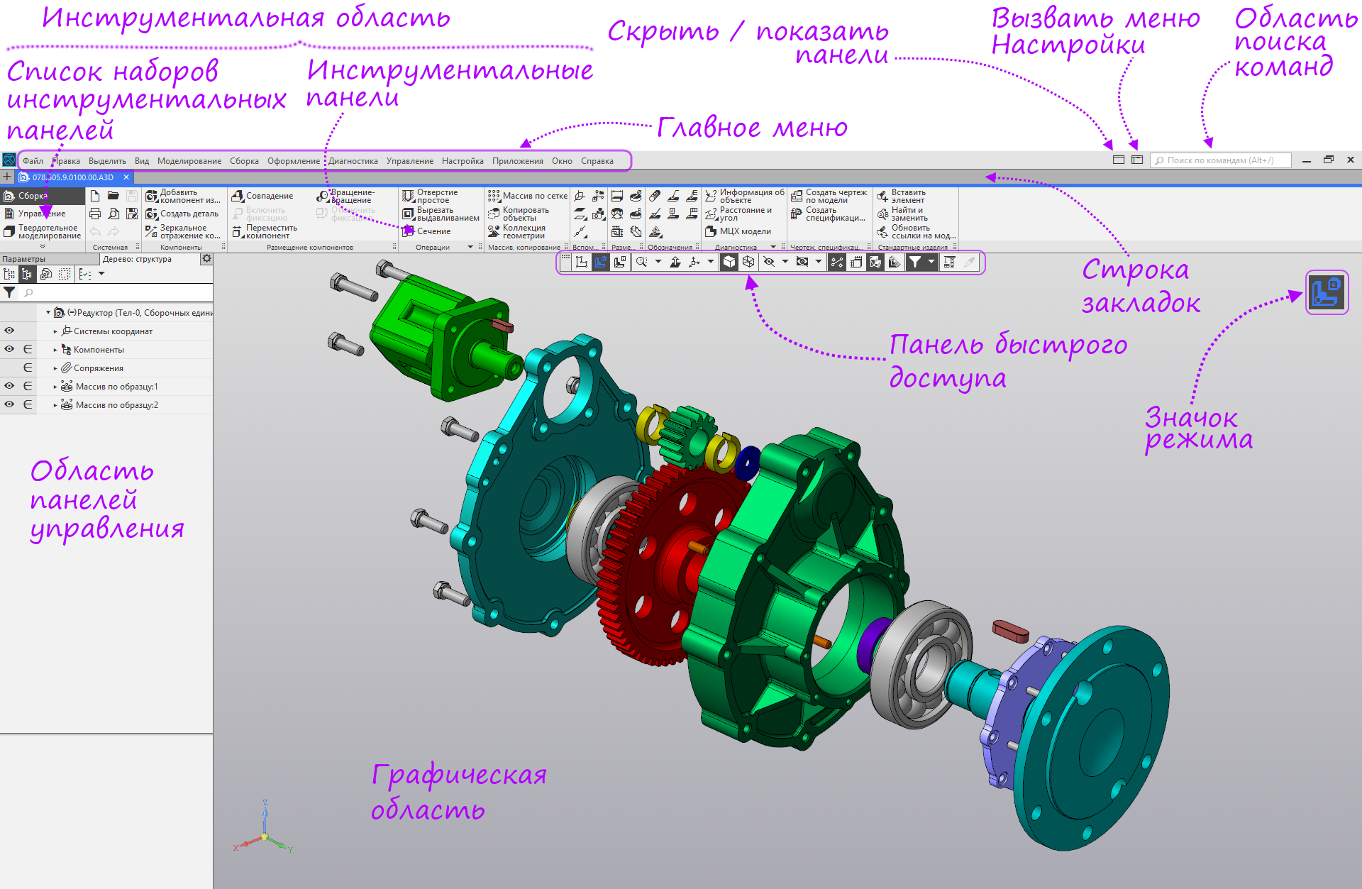
Interface
- The seventeenth KOMPAS-3D Home, like the whole KOMPAS family, switched to a new interface. The interface is reminiscent of the Ribbon, but operates on a different principle. The key feature is that the toolbox contains all the commands necessary for current activities.
- The entire interface is completely in Russian and supports Russian standards. That, actually, is not surprising for a Russian company.
- Rather familiar arrangement of menu items. There are, of course, small changes, but you quickly get used to them.
In the new version, the way of interaction with the mouse is unified — in the drawing and in the model, the middle button (or wheel) is responsible for moving, and the right button is responsible for rotating the model.
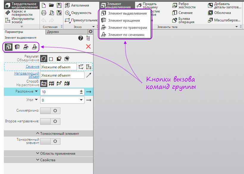
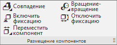
What is a group of teams?
The same type of team combined into groups. Inside the groups, the parameters of the command are saved to the maximum. Commands within a group can be switched at the top of the Options panel or selected from the drop-down panel that appears if you hold down the left mouse button on the main command in the toolbar.
Quick settings
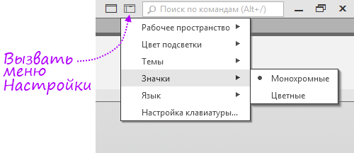
The most frequently used modes and settings are in a separate menu.
More about the Settings menu
In the Workspace menu, you can save changes to the workspace or return to the base one.

The backlight color is responsible for choosing the color of the inverse backlight of active commands and actions.
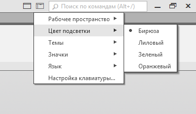
In the Theme menu, you can select the display mode of the workspace. It can be used for day and night mode.
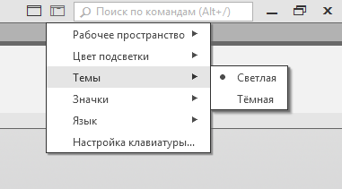
The Icons menu allows you to select color or monochrome icons.

There is only one Russian in the Language item)

Using the Keyboard Setup item, you can enter your own shortcuts for commands.

The settings window opens.

The backlight color is responsible for choosing the color of the inverse backlight of active commands and actions.
In the Theme menu, you can select the display mode of the workspace. It can be used for day and night mode.
The Icons menu allows you to select color or monochrome icons.
There is only one Russian in the Language item)
Using the Keyboard Setup item, you can enter your own shortcuts for commands.
The settings window opens.
The end of the description of the settings
The remaining settings are in the Options window.
More about the Options window
The Settings window starts from the Settings menu.

This window controls all the settings of both current documents and new ones, as well as the settings of the system as a whole. Each document type uses its own parameters for the current document.

This window controls all the settings of both current documents and new ones, as well as the settings of the system as a whole. Each document type uses its own parameters for the current document.
End of the description of the Parameters window
Options Panel
The settings panel is designed to manage the settings of the command.
Applications and Libraries
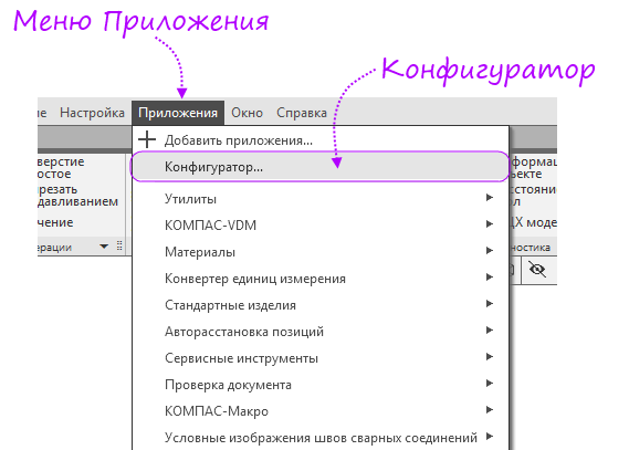
To work with applications and libraries there is a configurator, which is in the application menu.
After the call, the configurator window opens.
Search
The new version has several types of search.
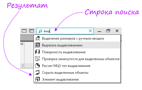
Team Search
Located in the upper right corner of the screen. Allows you to find the command you need by name.
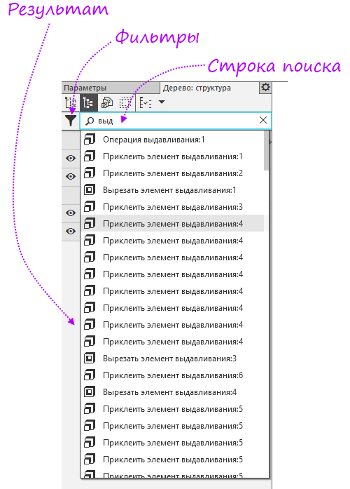
Search in the tree
Located at the top of the document tree. Allows you to find an operation or component in the tree. Tree search features complete the filters.
You can also use filters in the tree search.
The Filter field displays all available tree object types. If you are only looking for parts - turn on the appropriate filter, reducing the search area. You can also search for subassemblies, mates, design elements, standard products, curves, bodies, sketches, and coordinate systems.
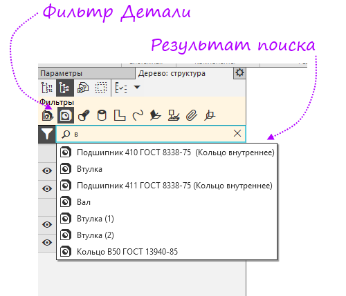
Search in the tree. Filter Details

Search in the tree. Filter Standard Products
Search in the tree. Filter Details
Search in the tree. Filter Standard Products
End of filter description
start page
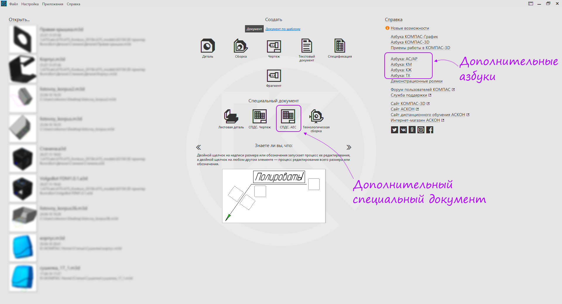
The first thing you see when starting the program is the start page. From there, you can create a new document, open an existing one, purchase and activate a license, start exploring the program with the help of educational materials and navigate to KOMPAS-3D websites and social networks to communicate and exchange experience with like-minded people.
More about the start page
Consider the start page in more detail.
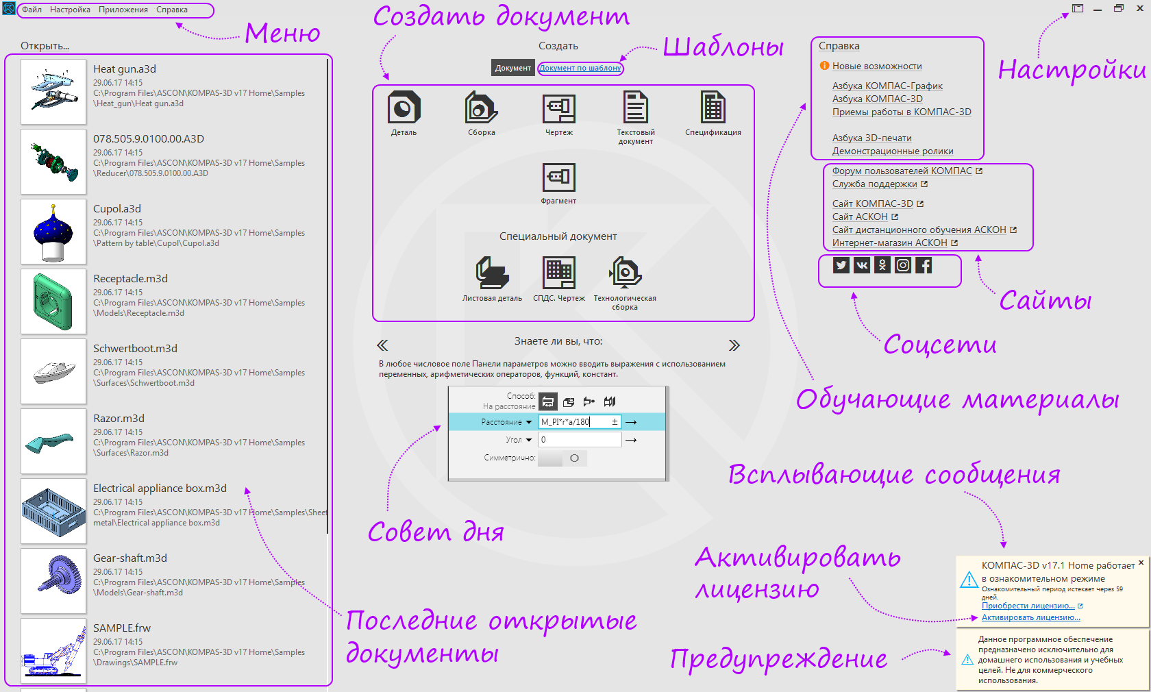
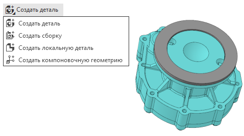
The start page is divided into four areas, also in the top line is the menu. On the left are the latest open documents, on the right - various links to useful materials. In the center of the bottom - the advice of the day, tips can be switched to learn something new about the program. Top center are buttons for creating new documents.
Available document types: part, assembly (combines previously created parts), drawing, fragment (similar to a drawing without a frame, is an analog of a dynamic block in an auto-caddy), a text document and a specification. Special documents are also available: Sheet detail, SPDS. Drawing, Technological assembly.
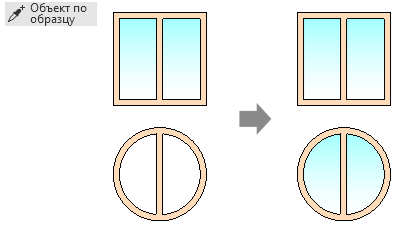
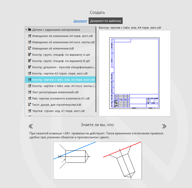
If you switch to the "Document by Template" mode, you can create a new document using the specified templates or the template you created.
If the building configuration has been established, additional alphabets and a new special document shall be added . AEC . The standard format of sheets (on A2) and the scale of views (on 1: 100) also change. There are other features.
Home configuration page

Drawing of a building configuration
The start page is divided into four areas, also in the top line is the menu. On the left are the latest open documents, on the right - various links to useful materials. In the center of the bottom - the advice of the day, tips can be switched to learn something new about the program. Top center are buttons for creating new documents.
Available document types: part, assembly (combines previously created parts), drawing, fragment (similar to a drawing without a frame, is an analog of a dynamic block in an auto-caddy), a text document and a specification. Special documents are also available: Sheet detail, SPDS. Drawing, Technological assembly.
Templates
If you switch to the "Document by Template" mode, you can create a new document using the specified templates or the template you created.
Features of the building configuration
If the building configuration has been established, additional alphabets and a new special document shall be added . AEC . The standard format of sheets (on A2) and the scale of views (on 1: 100) also change. There are other features.
Home configuration page
Drawing of a building configuration
End of start page description
License activation
The activation utility is needed to obtain a license.
Activation process
If something went wrong, we write to technical support .
If you still have questions on how to activate the product, here is a video on activating the license from our user:
- In the pop-up message, click "Activate the license."

- In the activation utility window that appears, click "Activate key".

- Enter the activation code from the letter that came from the online store. Click Next or, if you need to configure a proxy server, select "Settings".
 If you need to configure a proxy serverSelect the desired setting method, enter the data and click the Apply button.
The end of the description of the proxy server settings
- Enter your data (needed to restore the license). And click Register.
 If you have already registered beforeEnter only e-mail and click the checkbox "Already registered."
The end of the description of the mode "Already registered"
- Click "Activate".
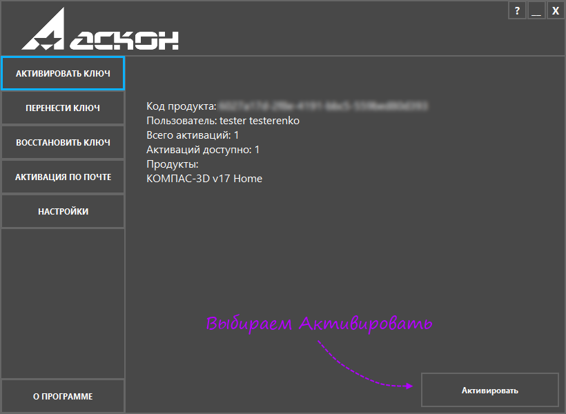
- Click "Go to the keys." The program is successfully activated.

If something went wrong, we write to technical support .
If you still have questions on how to activate the product, here is a video on activating the license from our user:
The end of the activation process
Basic document types
Here are the main documents and most of the commands that can be used in these documents.
Detail
Learn more about the interface and commands of the document. Detail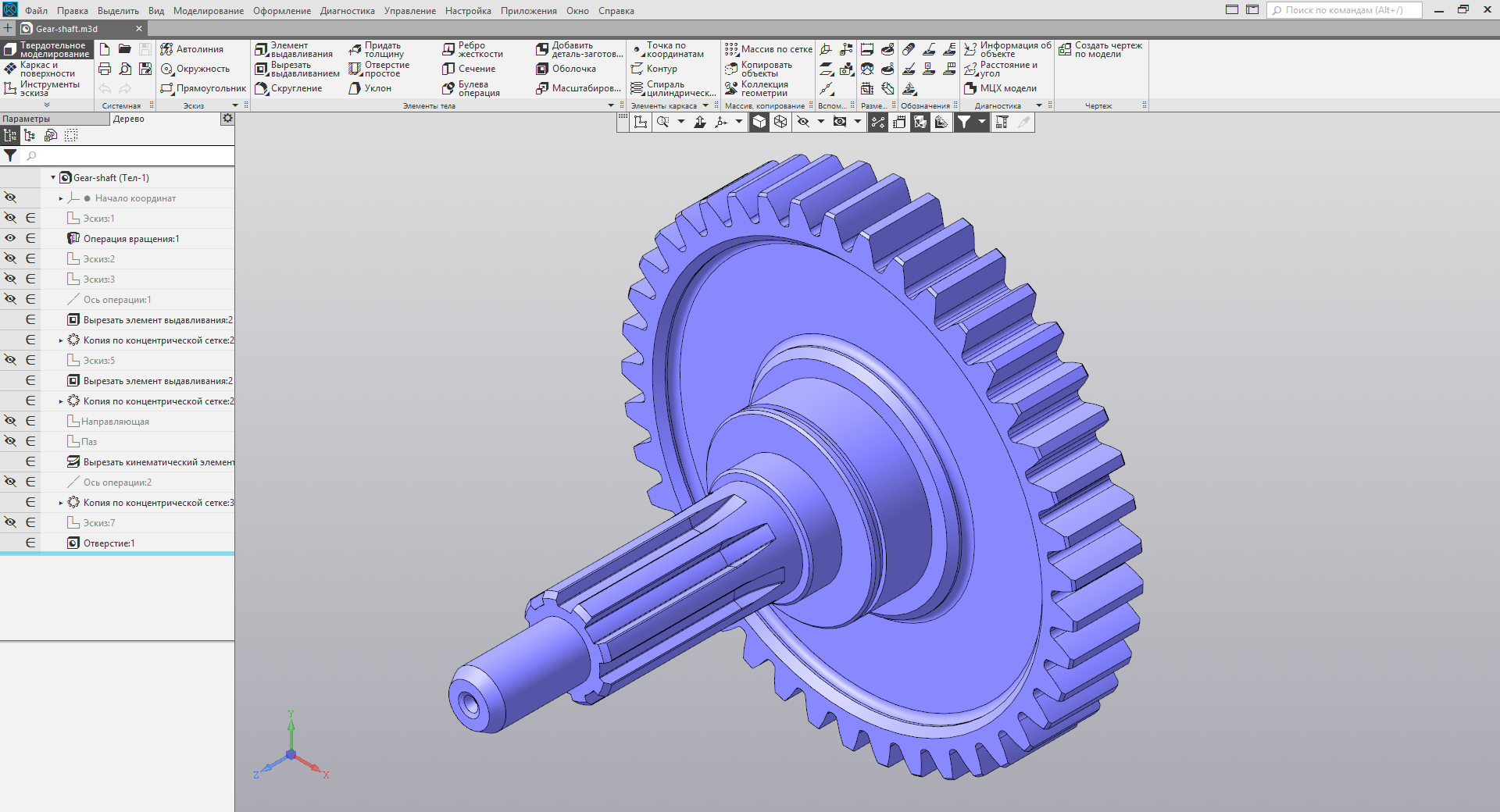
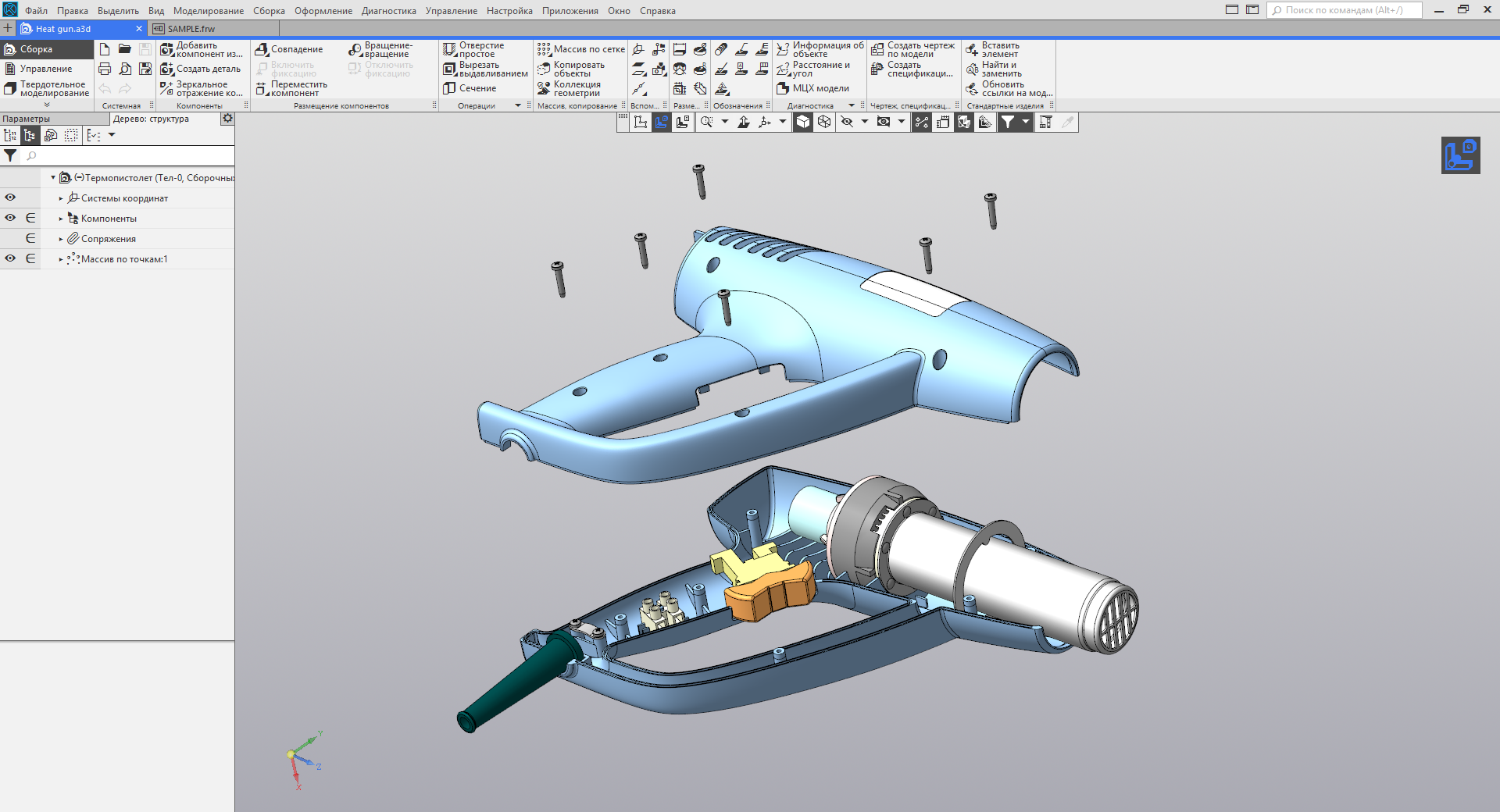
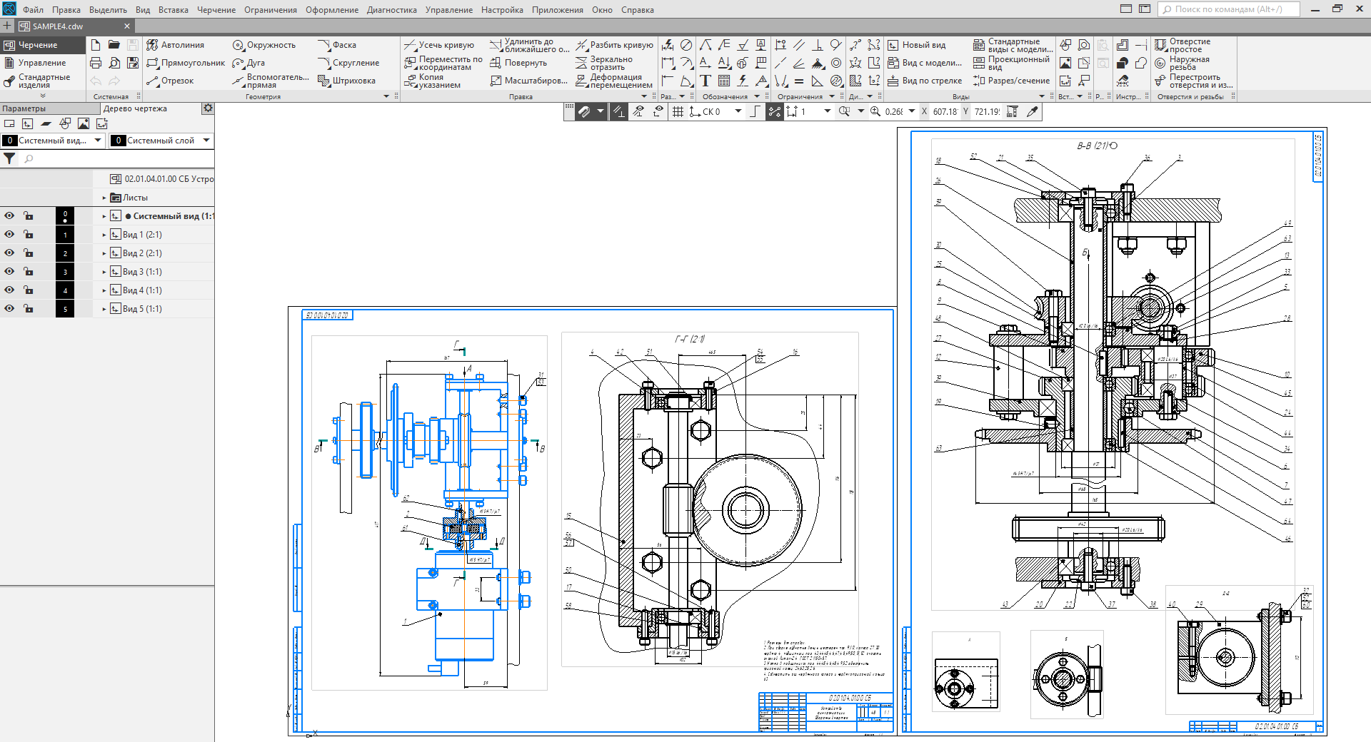
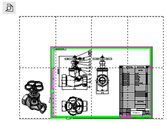
Document interface Detail and usage example (Picture is clickable)

All tools are divided into groups called toolbars.


, . , , .


, , , « ». , .
. . .
, . , .
, .
, .
, . , , . , , . , .
, .
, .
. .
.
.
, .

.
. .
, .
, .
, .
/
, .
, .
.
.
.
, .
.
, .
, .
, .
( ).
, , .
, .
.
.
.
.
, , .
( ).
.
17 — , , .
( ).
, .
.
.
, .
.
.
, , . .
.
.
, .
, .
.


Document interface Detail and usage example (Picture is clickable)
The number of sets in the documents depends on the installed applications and the applied configuration. Here only the basic sets are considered, the rest can be easily studied independently and with the help of a certificate.
Set Solid Modeling
First, consider in detail the set of Solid Modeling , because It is with his help that you can complete 90% of the tasks.
All tools are divided into groups called toolbars.
Read more about the panel set Solid Modeling

The System tab contains standard tools for creating a new document, opening a saved document, printing, canceling and repeating an action, and activating a preview.
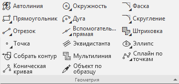
The Sketch panel contains the most frequently used tools for flat contouring.
The figure shows a view of the folded and unfolded panel.
The commands of this panel are used to transform a flat contour into a three-dimensional model or “solid body”, as well as to modify the resulting model in various ways.


System toolbar
The System tab contains standard tools for creating a new document, opening a saved document, printing, canceling and repeating an action, and activating a preview.
Systemic;
In this panel, everything is standard for any application. You can separately describe two commands that are used for printing, so that their difference is clear.
Print
Used for quick printing with a minimum of settings.

Preview
It is used to print multiple documents, the location of several documents on the format.

Used for quick printing with a minimum of settings.
Preview
It is used to print multiple documents, the location of several documents on the format.
The end of the description of the System panel
Dashboard Sketch
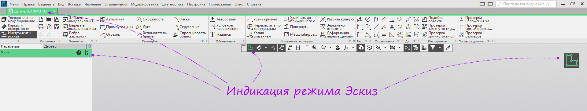
Most of the constructions in KOMPAS-3D begin with the construction of a sketch - a flat contour, which is then given volume by means of formative operations.
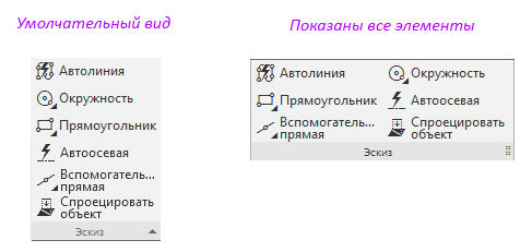
The Sketch panel contains the most frequently used tools for flat contouring.
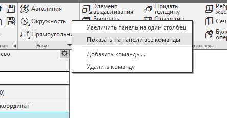
By default, the panel consists of one command line with three lines. The remaining commands are in the “basement”, which can be opened by clicking on the line with the name of the panel. If you are uncomfortable opening the “footer” every time, you can open the context menu and select Show all commands on the panel .
The figure shows a view of the folded and unfolded panel.
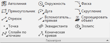
Sketch toolbar commands;
In this panel we see the tools:
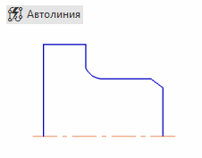
Autoline
This tool is needed to build a line that is drawn with dots. These points can be attached to other objects or set in any order. You need Autoline, for example, to build a contour of the figure. If you squeeze it in the future, you get a blank of the desired shape.
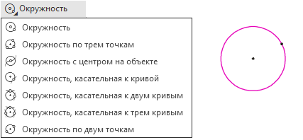
Circle
This element is a group of commands designed to build circles in different ways.
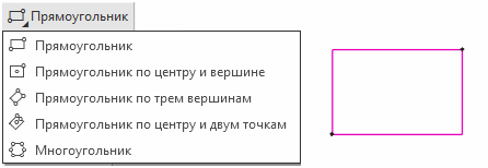
Rectangle
This element is a group of commands designed to build rectangles and polygons in various ways.
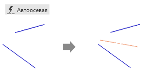
Auto Ax
The command is designed to simplify the creation of various types of centerlines.
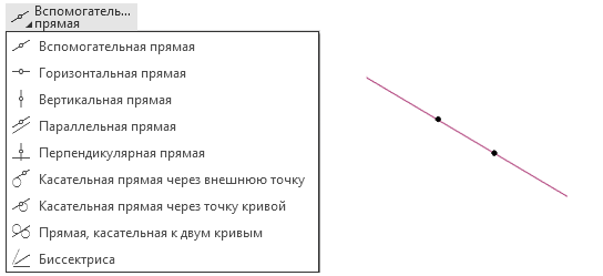
Auxiliary straight
A group of teams serves to create various auxiliary lines necessary for approximate constructions, and also helps inexperienced users to build basic geometry, since replaces a ruler or tire on the screen.
To project an object
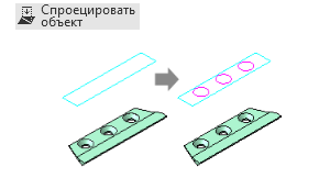
The team creates in the sketch a projection on the plane of geometry from a three-dimensional model or another sketch, which is parametrically connected with the source of the projection.

The process of placing the sketch on the plane
Autoline
This tool is needed to build a line that is drawn with dots. These points can be attached to other objects or set in any order. You need Autoline, for example, to build a contour of the figure. If you squeeze it in the future, you get a blank of the desired shape.
Circle
This element is a group of commands designed to build circles in different ways.
Rectangle
This element is a group of commands designed to build rectangles and polygons in various ways.
Auto Ax
The command is designed to simplify the creation of various types of centerlines.
Auxiliary straight
A group of teams serves to create various auxiliary lines necessary for approximate constructions, and also helps inexperienced users to build basic geometry, since replaces a ruler or tire on the screen.
To project an object
The team creates in the sketch a projection on the plane of geometry from a three-dimensional model or another sketch, which is parametrically connected with the source of the projection.
After activating any of these commands, the system starts the process of placing the sketch on the plane, and then goes into sketch mode. Sketch mode is a normal drawing on a plane. In sketch mode, a set of sketch tools opens - accordingly, additional commands appear.
The process of placing the sketch on the plane
End description of the Sketch panel.
Toolbar Body elements
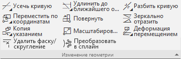
The commands of this panel are used to transform a flat contour into a three-dimensional model or “solid body”, as well as to modify the resulting model in various ways.
Commands panel body elements
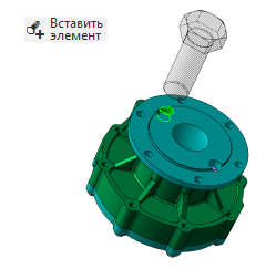
Extrusion Element
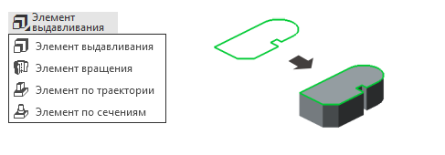
This element is a group of commands designed to build shaping elements. Extrusion is necessary in order to give the specified contour a volume by extruding it in the indicated forward direction. Rotation adds volume by rotating the contour around the axis of symmetry. The element along the path ( earlier this command was called Kinematic operation ) adds volume to the contour along the path specified by the user. The element on sections creates a solid body from several specified flat contours.
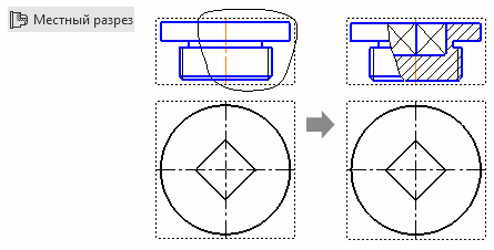
Extrude cut
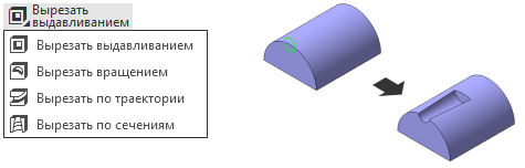
This element is a group of commands designed to cut from the body the same elements that are added to the previous group of commands.
Rounding
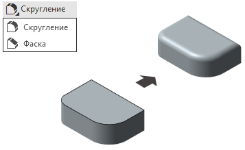
This element is a group of commands for building.
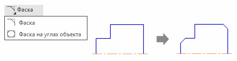
Hole simple
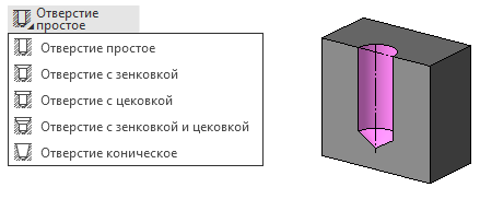
This element is a group of commands that allow you to make holes in the workpieces by giving them diameter and depth. Also here is the chamfer.
Boolean operation
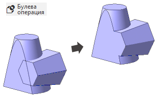
This function is needed to subtract or remove the volume of a particular body from another object. It may be necessary, for example, when we need to cut the shape of an asterisk in a rectangle or make holes for bolts.
Thicken
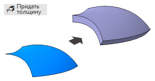
This command adds a layer of material to a face or surface.
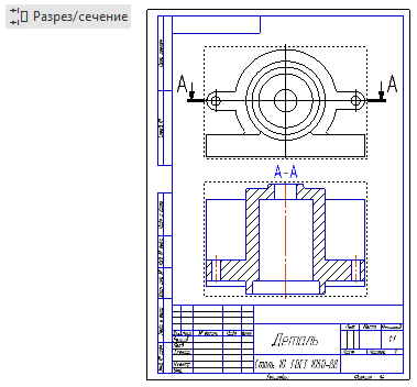
Section

This command cuts off part of the body using a sketch, plane or surface.
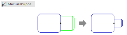
To scale
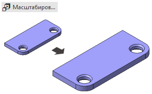
This command proportionally changes the size of the body or the whole part.
Stiffener

A stiffener is needed to give strength to any structure, especially in those places where it is impractical to put a full-fledged wall.
Shell
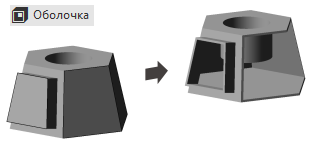
The shell leaves a thin layer of material from the body, deposited on the outer or inner surface left over from the body.
Change position
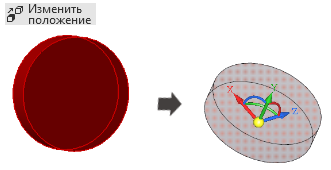
Creates a new solid, surface or part by changing the position of an existing object.
Add workpiece detail ...
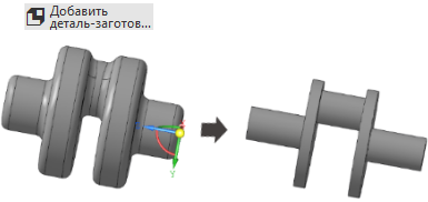
With this function, you can add any part that you previously saved to our project.
Bias
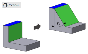
This command tilts the existing face with respect to the other face.
This element is a group of commands designed to build shaping elements. Extrusion is necessary in order to give the specified contour a volume by extruding it in the indicated forward direction. Rotation adds volume by rotating the contour around the axis of symmetry. The element along the path ( earlier this command was called Kinematic operation ) adds volume to the contour along the path specified by the user. The element on sections creates a solid body from several specified flat contours.
Extrude cut
This element is a group of commands designed to cut from the body the same elements that are added to the previous group of commands.
Rounding
This element is a group of commands for building.
Hole simple
This element is a group of commands that allow you to make holes in the workpieces by giving them diameter and depth. Also here is the chamfer.
Boolean operation
This function is needed to subtract or remove the volume of a particular body from another object. It may be necessary, for example, when we need to cut the shape of an asterisk in a rectangle or make holes for bolts.
Thicken
This command adds a layer of material to a face or surface.
Section
This command cuts off part of the body using a sketch, plane or surface.
To scale
This command proportionally changes the size of the body or the whole part.
Stiffener
A stiffener is needed to give strength to any structure, especially in those places where it is impractical to put a full-fledged wall.
Shell
The shell leaves a thin layer of material from the body, deposited on the outer or inner surface left over from the body.
Change position
Creates a new solid, surface or part by changing the position of an existing object.
Add workpiece detail ...
With this function, you can add any part that you previously saved to our project.
Bias
This command tilts the existing face with respect to the other face.
End of body parts panel description.
Toolbar Frame elements
Toolbar commands Frame elements;
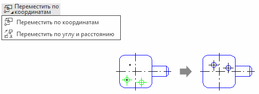
Point by coordinates

A group of commands for creating various three-dimensional points: by coordinates, transfer of existing ones, points lying on curves and surfaces, intersections and projections.
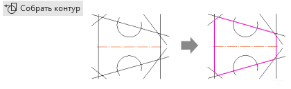
Circuit
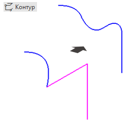
Creates a three-dimensional contour on the basis of the objects contained in the detail: curves, edges, sketches.
Cylindrical spiral

A group of teams to create various three-dimensional cylindrical and conical spirals.
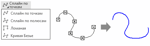
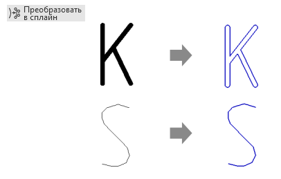
Spline on points

A group of commands for creating various three-dimensional splines by points and poles.
A group of commands for creating various three-dimensional points: by coordinates, transfer of existing ones, points lying on curves and surfaces, intersections and projections.
Circuit
Creates a three-dimensional contour on the basis of the objects contained in the detail: curves, edges, sketches.
Cylindrical spiral
A group of teams to create various three-dimensional cylindrical and conical spirals.
Spline on points
A group of commands for creating various three-dimensional splines by points and poles.
The end of the description of the frame elements panel.
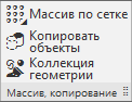
Toolbar Array, copy
Commands of the toolbar Array, copy;
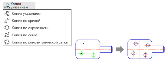
Grid array
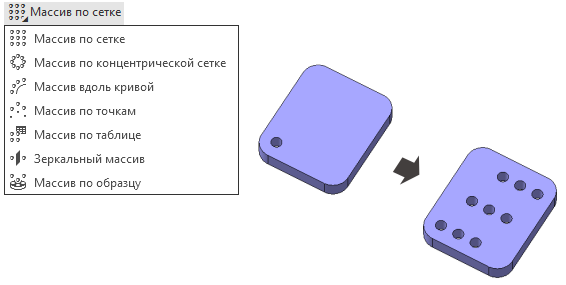
A group of commands for creating various arrays (a set of homogeneous bodies, operations or parts)
Copy objects
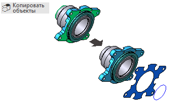
Creates a copy of three-dimensional geometric objects: vertices, edges, faces, surfaces and bodies. The copy remains associatively related to the original object.
Geometry Collection
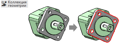
Creates a collection of three-dimensional geometric objects: vertices, edges, faces, surfaces and bodies. The collection serves for the convenience of copying geometry between different parts or assemblies: instead of copying each individual geometric object, the collection is immediately copied.
A group of commands for creating various arrays (a set of homogeneous bodies, operations or parts)
Copy objects
Creates a copy of three-dimensional geometric objects: vertices, edges, faces, surfaces and bodies. The copy remains associatively related to the original object.
Geometry Collection
Creates a collection of three-dimensional geometric objects: vertices, edges, faces, surfaces and bodies. The collection serves for the convenience of copying geometry between different parts or assemblies: instead of copying each individual geometric object, the collection is immediately copied.
The end of the description of the panel array, copying
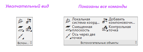
Toolbar Auxiliary Items
Toolbar Commands Auxiliary Items;
Local coordinate system
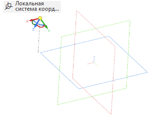
Creates a new coordinate system, which can be shifted to some distance from the existing one, and also rejected by some angle.
Offset plane

A group of commands designed to create planes in different ways.
Axis through two points
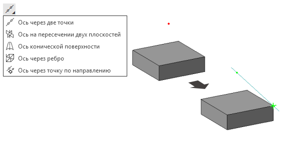
A group of commands designed to create different axes.
Add layout geometry from file ;

Adds to the model layout geometry, which is convenient to use to study the design of the product.
Check Point

A group of teams designed to create connection points used to place parts in an assembly.
Creates a new coordinate system, which can be shifted to some distance from the existing one, and also rejected by some angle.
Offset plane
A group of commands designed to create planes in different ways.
Axis through two points
A group of commands designed to create different axes.
Add layout geometry from file ;
Adds to the model layout geometry, which is convenient to use to study the design of the product.
Check Point
A group of teams designed to create connection points used to place parts in an assembly.
End of the description of the panel Auxiliary Elements
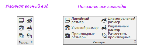
Toolbar Dimensions
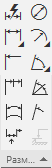
Toolbar Commands Sizes;
Linear size
Puts a linear dimension between two model objects.
Diameter size
Dimensional dimension on cylindrical, conical, spherical or toroidal face of the model.
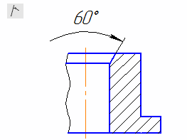
Angular size
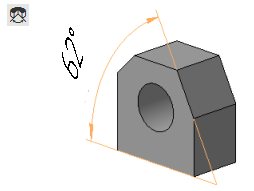
Puts an angular dimension between two straight or flat model objects.
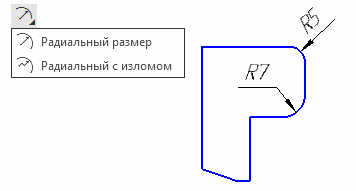
Radial size

Puts a radial dimension on a cylindrical, conical, spherical, or toroidal face of the model.
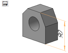
Derived size

Creates a derived size based on the dimensions of the sketch or operation.
Place derived dimensions
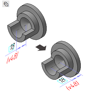
Moves the derived size from its current plane to another.
Puts a linear dimension between two model objects.
Diameter size
Dimensional dimension on cylindrical, conical, spherical or toroidal face of the model.
Angular size
Puts an angular dimension between two straight or flat model objects.
Radial size
Puts a radial dimension on a cylindrical, conical, spherical, or toroidal face of the model.
Derived size
Creates a derived size based on the dimensions of the sketch or operation.
Place derived dimensions
Moves the derived size from its current plane to another.
The end of the panel size description.
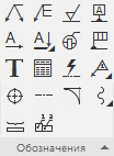
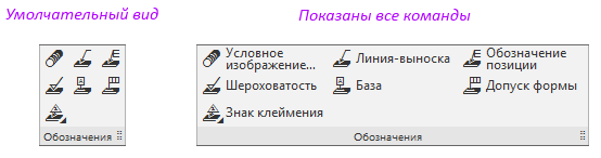
Toolbar Designations
Commands of the toolbar Designations;
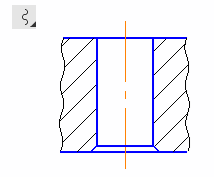
Conditional thread image
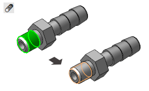
Creates a conditional thread image on a cylindrical or conical face of the model.
Leader Line

Creates a three-dimensional leader line in the model.
Position Designation
Creates a three-dimensional designation of the position in the model.
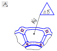
Roughness
Creates a roughness symbol in the model.
Base
Creates a base designation in the model.
Form tolerance
Creates a form tolerance symbol in the model.
Mark of Branding

A group of commands designed to create marks of marking and marking in the model.
Creates a conditional thread image on a cylindrical or conical face of the model.
Leader Line
Creates a three-dimensional leader line in the model.
Position Designation
Creates a three-dimensional designation of the position in the model.
Roughness
Creates a roughness symbol in the model.
Base
Creates a base designation in the model.
Form tolerance
Creates a form tolerance symbol in the model.
Mark of Branding
A group of commands designed to create marks of marking and marking in the model.
The end of the description of the panel designations
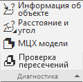
Diagnostics toolbar
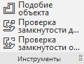
Diagnostics toolbar commands;
Property Information
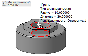
Shows all available information about the specified object: point, edge, face, body, part, assembly.
Distance and angle
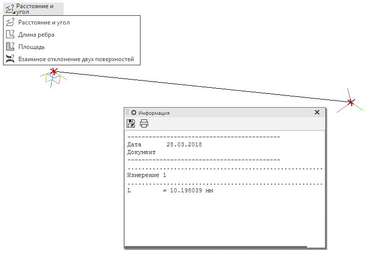
A group of commands designed to obtain information about distances and angles between objects, curve lengths, areas, and the relative position of objects.
ICC model
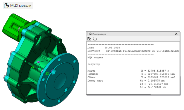
Shows the mass-centering characteristics of the body, part or assembly.
Intersection check

Shows intersections and tangencies between bodies, parts, or assemblies.
Shows all available information about the specified object: point, edge, face, body, part, assembly.
Distance and angle
A group of commands designed to obtain information about distances and angles between objects, curve lengths, areas, and the relative position of objects.
ICC model
Shows the mass-centering characteristics of the body, part or assembly.
Intersection check
Shows intersections and tangencies between bodies, parts, or assemblies.
End description of the Diagnostics panel
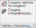
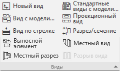
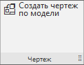
Toolbar Drawing
Toolbar Commands Drawing
In this group there is only one team - Create a drawing by model .
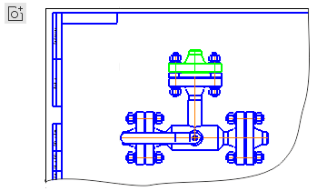
Create a drawing by model

Creates a drawing on a part or assembly.
Create a drawing by model
Creates a drawing on a part or assembly.
End of panel description. Drawing.
The end of the description of the set. Solid modeling
Set Sheet Modeling
Sheet modeling is used to create sheet details.
More about the set
A feature of sheet bodies is the ability to get a scan of the sheet body with the press of a single button.
Only the toolbar Elements of the sheet body is unique.

Only the toolbar Elements of the sheet body is unique.
Toolbar Elements of the sheet body
Panel Commands Leaf Body Elements
Speech only about unique teams. The Rounding command is already described in the Solid Modeling set, if the command’s functionality is not clear, read about it in the description of the corresponding set.
Leaf body

Team group Creates a new flat or curved sheet body, depending on the selected sketch.
Fold

A group of commands designed to add a new fold or several folds to the sheet body.
Straighten

A group of commands designed to straighten existing folds and flexing back.
Shell
Creates a straight shell based on the selected sketch.
Cut in sheet body

A group of commands designed to create a cutout or hole in the sheet body.
Corner closure

Creates a closure of the corners between the two folds of the leaf body.
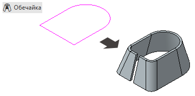
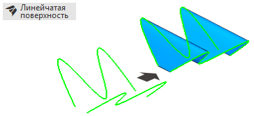
Ruled shell
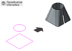
Creates a shell based on two sketches that form the top and bottom of the shell.
Open stamping
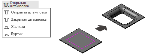
A group of teams designed to create various stampings and stiffeners.
Leaf body
Team group Creates a new flat or curved sheet body, depending on the selected sketch.
Fold
A group of commands designed to add a new fold or several folds to the sheet body.
Straighten
A group of commands designed to straighten existing folds and flexing back.
Shell
Creates a straight shell based on the selected sketch.
Cut in sheet body
A group of commands designed to create a cutout or hole in the sheet body.
Corner closure
Creates a closure of the corners between the two folds of the leaf body.
Ruled shell
Creates a shell based on two sketches that form the top and bottom of the shell.
Open stamping
A group of teams designed to create various stampings and stiffeners.
End of panel description. Elements of the sheet body.
End of set description. Sheet modeling
Frame and surface set
To create parts of complex shape is a set of frame and surface .
More about the set
Only the Surface toolbar is unique. Also, in comparison with the Solid Modeling set, the Frame panel was expanded.


, .

.

, .

, .

, .

.

.

.
, .

, .

.

, .

.

.

.

, .
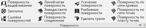
Toolbar Surfaces
Surface Toolbar Commands
Extrusion surface
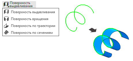
A group of commands designed to create shaping surfaces. Extrusion is necessary in order to create a surface from a given contour by extruding it in the indicated forward direction. . . .

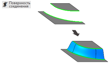
-, - , .
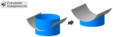
, , . .

.
. .
. , .
.
, .
. , , . , .

, .
. , .

, , .
. , ( ).

.
, , 3D-, , . .

, , 3D-, , . — .
A group of commands designed to create shaping surfaces. Extrusion is necessary in order to create a surface from a given contour by extruding it in the indicated forward direction. . . .
-, - , .
, , . .
.
. .
. , .
.
, .
. , , . , .
, .
. , .
, , .
. , ( ).
.
, , 3D-, , . .
, , 3D-, , . — .
, .
.
, .
, .
, .
.
.
.
, .
, .
.
, .
.
.
.
, .
, . , , .
-3D — , . . , .
, , , « ». , .
. . .
, . , .
, .
, .
, . , , . , , . , .
, .
, .
. .
.
.
, .
.
. .
, .
, .
, .
/
, .
, .
.
.
.
, .
.
, .
, .
, .
( ).
, , .
, .
.
.
.
.
, , .
( ).
.
17 — , , .
( ).
, .
.
.
, .
.
.
, , . .
.
.
, .
, .
.
( )
, — , , .
, .
...

.
, .

, .
...
.
, .
, .
, .
.
, .
.
-
, .
,
,
, , .

.
.
,
,
-3D , .
, -3D , , .
, , , . -3D, , , . .
( )
, , , .
, , , , . .
, .
, . . , , . , .
, .
, .
, , , .. .
, .
, .
, . , , , , . , , . , .
, .
, .
. .
.
.
, .
, , .
, .
, , .
.
, .
, .
, .
/
, .
, .
.
.
.
, .
.
, .
, .
, .
.
.
, .
, .
( ).
, , .
, .
.
.
.
.
, , .
( ).
.
.
.
. .
.
-
- .
.
.
.
. , , .
/
, . , , .
, .
.
.
.
, .
.
.
.
.
-.
.
.
17 — , , .
( ).
, .
.
.
, .
.
.
, , . .
.
.
, .
, .
.
.
.
.
- .
, .
.
.
- , .
- , .
.
...
.
, .
.
.
...
.
, , .
/
/ , .
, .
.
, , .
...

.
...

.
...
.
.

.
.
-
- .

.
.
...
.
...
.
.
.
.
-
- .
.
, « -3D». « -3D» 17 .
.
. , .
« -3D»
« -3D»
, .
.
/
.
.
, , .
.
( ).
, ,
( )
. , .. . .
( )
, . , .
.
.
. .
( )
. , . , .
.
— , , — .
, . , .
.
( )
.
. ( )
«-» . .
( )
( )
3D- ,
- PLM
- — « »
- (Home , Home)
- (Home — 1 , — )
- .
- 60
-3D , «». « -», « -3D» « ».
-3D Home « 3D-», , 3D-.
. , .

« »
, — . Home . — ?

« »
— .

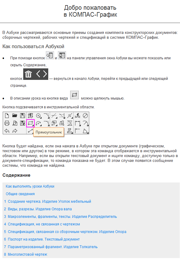
ABC COMPASS-Graph
Content
How to perform ABC lessons
General information
1 Creating a drawing. Furniture Corner
2 Types, cuts. Shaft support
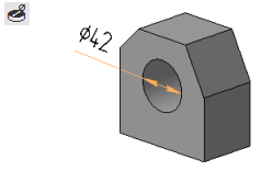
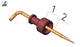
3 Macroelements, fragments, texts. Product Dispenser
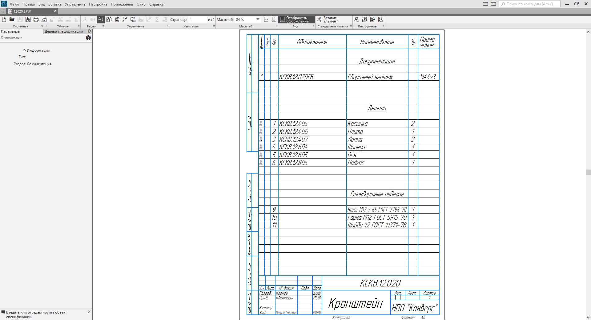
4 Non-drawing specification
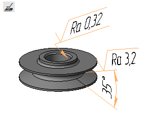
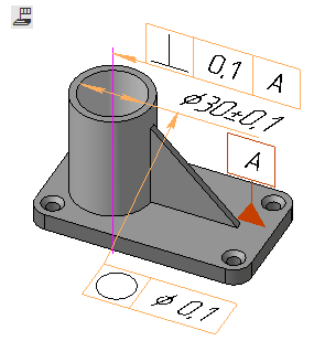
5 Specification related to the assembly drawing. Product Support
6 Passport to the product. Text Document
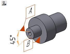
7 Parameterized fragment. Product Pusher
8 Multiple drawing
Alphabet KOMPAS-3D

Content
How to perform ABC lessons
General information
1 Extrusion operation. Model Fork
2 Rotation operation. Model Insert
3 Kinematic operation. Model Blade
4 Section operation. Hammer Model
5 Build creation. Model Holder
6 Creating drawings and assembly specifications. Model Holder
7 Bending operations, closing angles. Model Case
8 Bending and punching operations. Planck's model
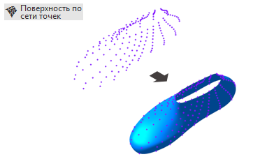
9 Surface on a network of points. Shoe model shoe
10 Surface on a network of curves. Model Boat
Work techniques in KOMPAS-3D

Content
How to learn work practices
1 Table array. Model Massage mat
2 Performances. Creating performances. Model Contact Element
3 Performances. Drawing design and specifications. Model Contact Element
4 Groups of components. Model Reducer
5 Accounting tolerances in the model. Housing model with lid
6 Creating and using a library of models. Model rake
7 Creating a mirror assembly. Model Headphones
8 Creating a split body of complex shape. Telephone handset model
9 Design from several sides. Model Lever
10 Prototype modeling. Furniture loop model
11 Bottom-up design with component placement. Model Guide block
12 Design from bottom to top with pre-layout. Drive case model
13 Design from top to bottom with pre-layout. Model Stapler
14 Design from top to bottom with the transformation of bodies into components. Model Prop
15 Preparing for teamwork. Model Clamp
16 Collective work on the assembly. Model Clamp

Content
Procedure
1 Printing Objects
2 Creating a part
3 Model requirements for printing
When installing the building configuration, the alphabets for building applications are also set.

Building Alphabet
ABC Architecture: AS / AP

Content
Lesson number 1. Creating a floor plan
Lesson number 2. Creating a 3D model of the building
Lesson number 3. Design project
Lesson number 4. Interior design and the creation of photo-realistic image
ABC Power Supply: ES / EM

Content
Lesson number 1. Placing electrical equipment on the plan
Lesson number 2. Single-line calculation scheme
Lesson number 3. Building a 3D model and obtaining specifications
The ABC of Life Support: OB

Content
Lesson 1. Building ventilation
Lesson 2. Creating a cut
Lesson 3. Creating a specification
ABC app Life Support: VK

Content
Lesson 1. Building water
Lesson 2. Drainage of a building
« »
, — . Home . — ?
« »
— .
, — , .
ABC COMPASS-Graph
Content
How to perform ABC lessons
General information
1 Creating a drawing. Furniture Corner
2 Types, cuts. Shaft support
3 Macroelements, fragments, texts. Product Dispenser
4 Non-drawing specification
5 Specification related to the assembly drawing. Product Support
6 Passport to the product. Text Document
7 Parameterized fragment. Product Pusher
8 Multiple drawing
Alphabet KOMPAS-3D
Content
How to perform ABC lessons
General information
1 Extrusion operation. Model Fork
2 Rotation operation. Model Insert
3 Kinematic operation. Model Blade
4 Section operation. Hammer Model
5 Build creation. Model Holder
6 Creating drawings and assembly specifications. Model Holder
7 Bending operations, closing angles. Model Case
8 Bending and punching operations. Planck's model
9 Surface on a network of points. Shoe model shoe
10 Surface on a network of curves. Model Boat
Work techniques in KOMPAS-3D
Content
How to learn work practices
1 Table array. Model Massage mat
2 Performances. Creating performances. Model Contact Element
3 Performances. Drawing design and specifications. Model Contact Element
4 Groups of components. Model Reducer
5 Accounting tolerances in the model. Housing model with lid
6 Creating and using a library of models. Model rake
7 Creating a mirror assembly. Model Headphones
8 Creating a split body of complex shape. Telephone handset model
9 Design from several sides. Model Lever
10 Prototype modeling. Furniture loop model
11 Bottom-up design with component placement. Model Guide block
12 Design from bottom to top with pre-layout. Drive case model
13 Design from top to bottom with pre-layout. Model Stapler
14 Design from top to bottom with the transformation of bodies into components. Model Prop
15 Preparing for teamwork. Model Clamp
16 Collective work on the assembly. Model Clamp
Alphabet of 3D printing (COMPAS Home)
Content
Procedure
1 Printing Objects
2 Creating a part
3 Model requirements for printing
Building Alphabet
When installing the building configuration, the alphabets for building applications are also set.
Building Alphabet
ABC Architecture: AS / AP
Content
Lesson number 1. Creating a floor plan
Lesson number 2. Creating a 3D model of the building
Lesson number 3. Design project
Lesson number 4. Interior design and the creation of photo-realistic image
ABC Power Supply: ES / EM
Content
Lesson number 1. Placing electrical equipment on the plan
Lesson number 2. Single-line calculation scheme
Lesson number 3. Building a 3D model and obtaining specifications
The ABC of Life Support: OB
Content
Lesson 1. Building ventilation
Lesson 2. Creating a cut
Lesson 3. Creating a specification
ABC app Life Support: VK
Content
Lesson 1. Building water
Lesson 2. Drainage of a building
End of description Azbook
Short modeling lessons
Here are three small construction lessons on the main types of modeling. Lessons do not intersect with the ABC, so it will be a good addition to them.
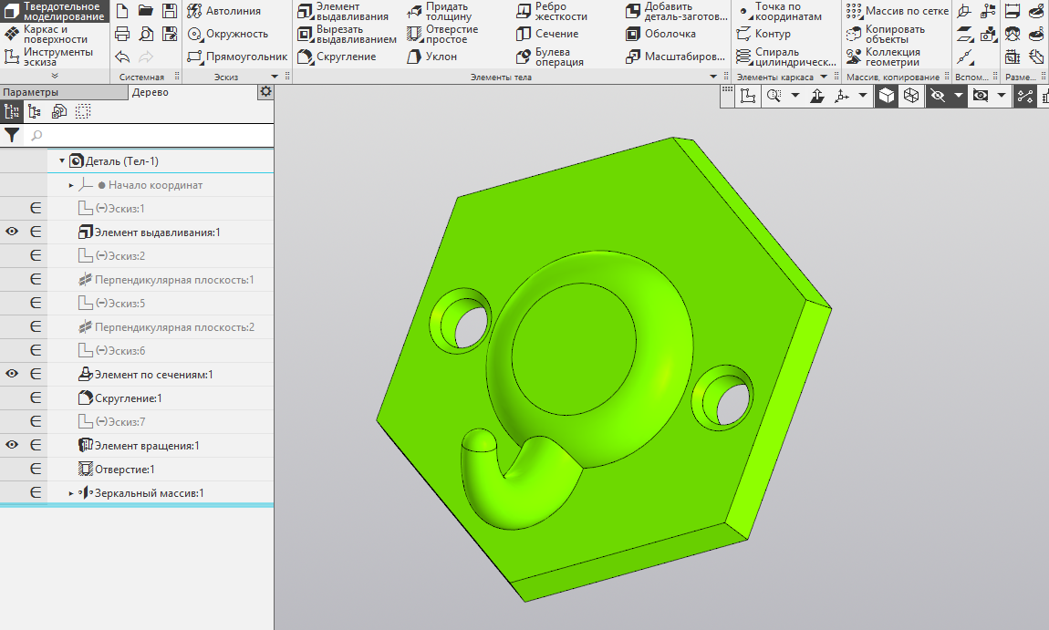
Printed hanger
The process of modeling a solid model
- First create a new document Detail.
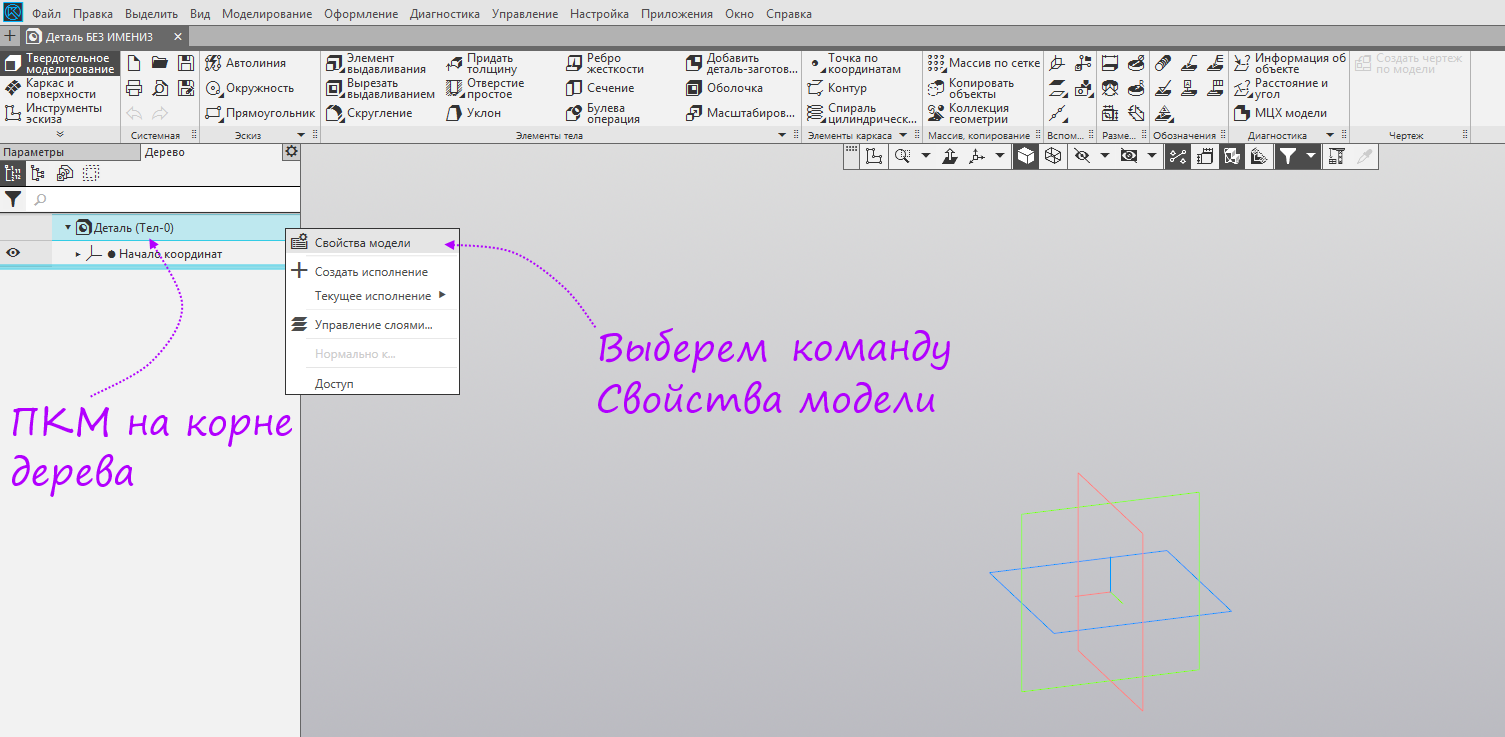
- Let's right-click on the root element of the tree and select “Model properties” in the context menu.
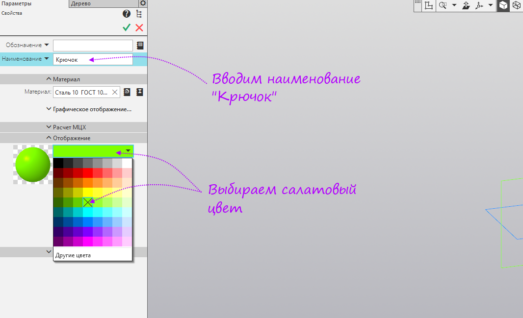
- Enter the name of the model "Hook". Choose any color you like, for example, Lime.
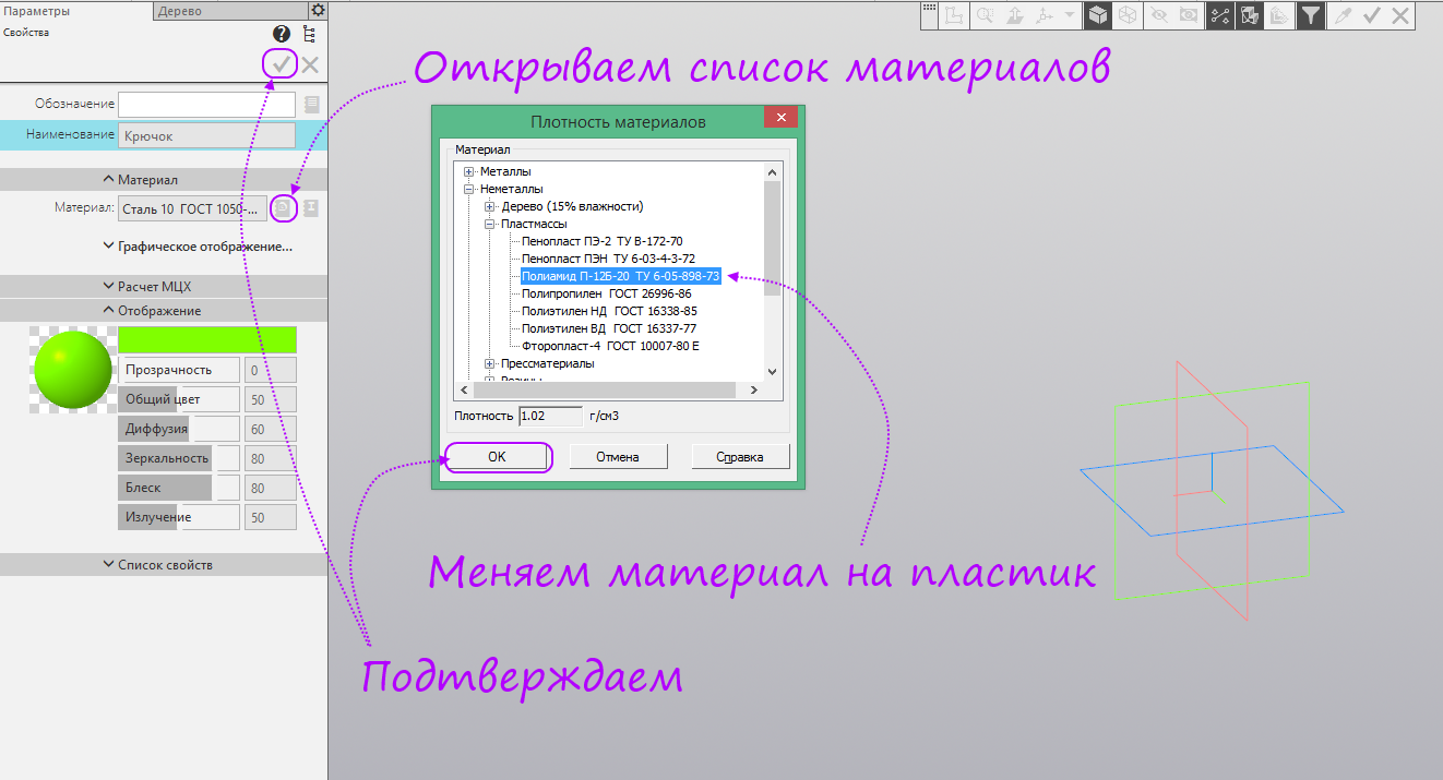
- Open the list of materials, choose any plastic. Click OK in the “Material Density” window and Create in the Parameters panel.
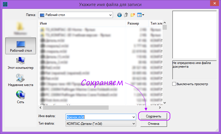
- Click Save As to save the item.
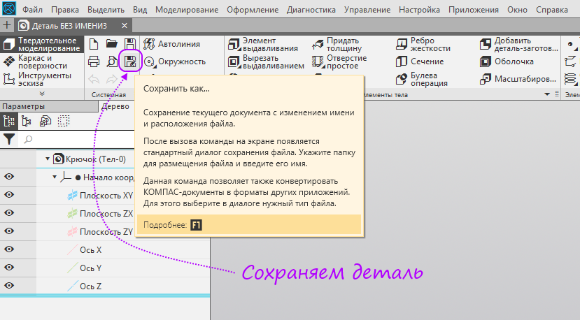
- Select the folder in which to save the model and click Save.
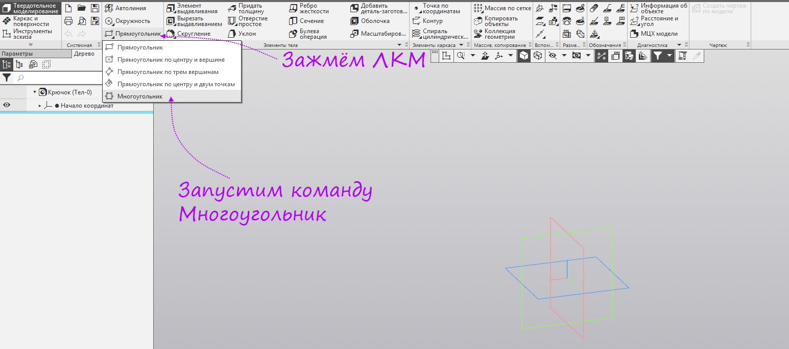
- We hold down the left mouse button on the “Rectangle” command group, in the opened panel, select “Polygon”.
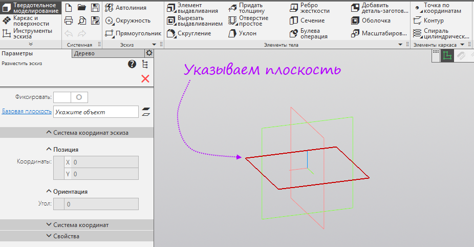
- Specify the XY plane.
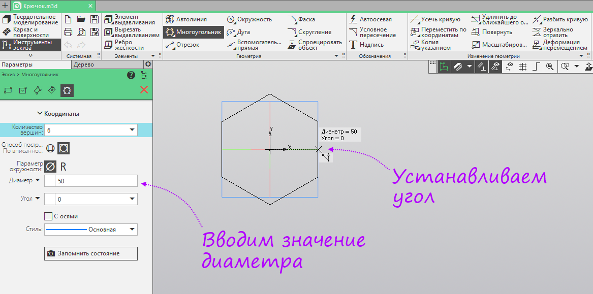
- Build a polygon from the origin. Set the number of vertices - 6 pieces, diameter 50 mm. Specify the angle - 0 degrees.
- Without completing the previous command, run the Extrusion command.
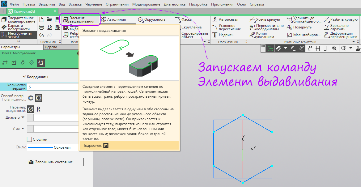
- Enter the distance - 5 mm, angle - 10 degrees and, if necessary, change the direction of the angle. Not completing the previous command, click the button Sketch.

- Specify the ZY plane.

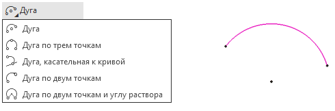
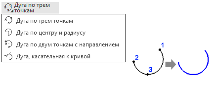
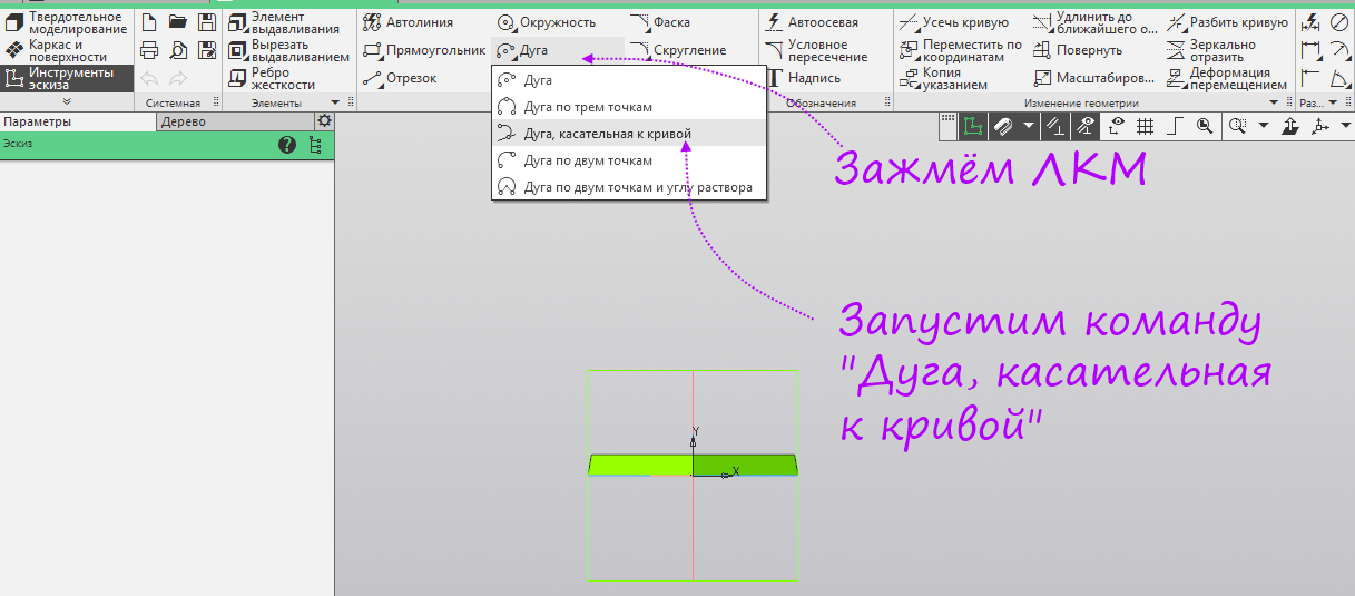
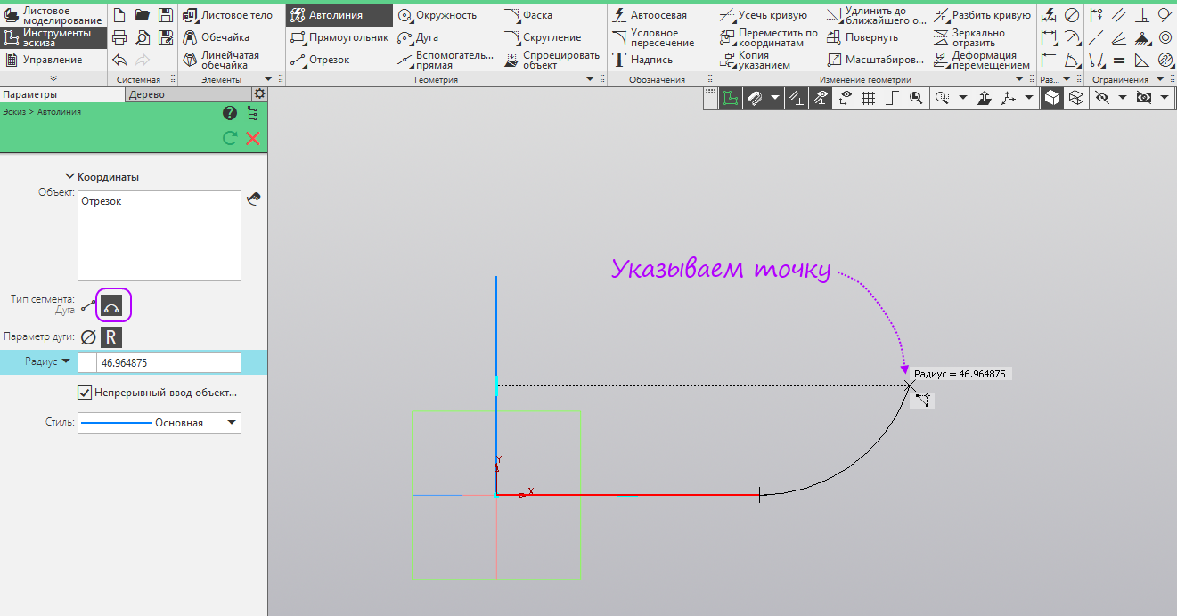
- Clamp the left mouse button on the “Arc” command group, in the opened panel, select “Arc, tangent to the curve”.
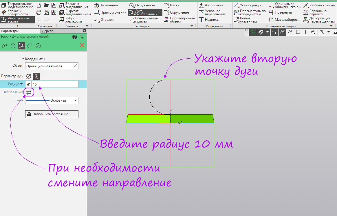
- Specify a segment for tangency and arbitrarily specify the starting point of the arc.

- Enter the radius of the arc 10, if necessary, change the direction of the arc and arbitrarily indicate the end point of the arc.
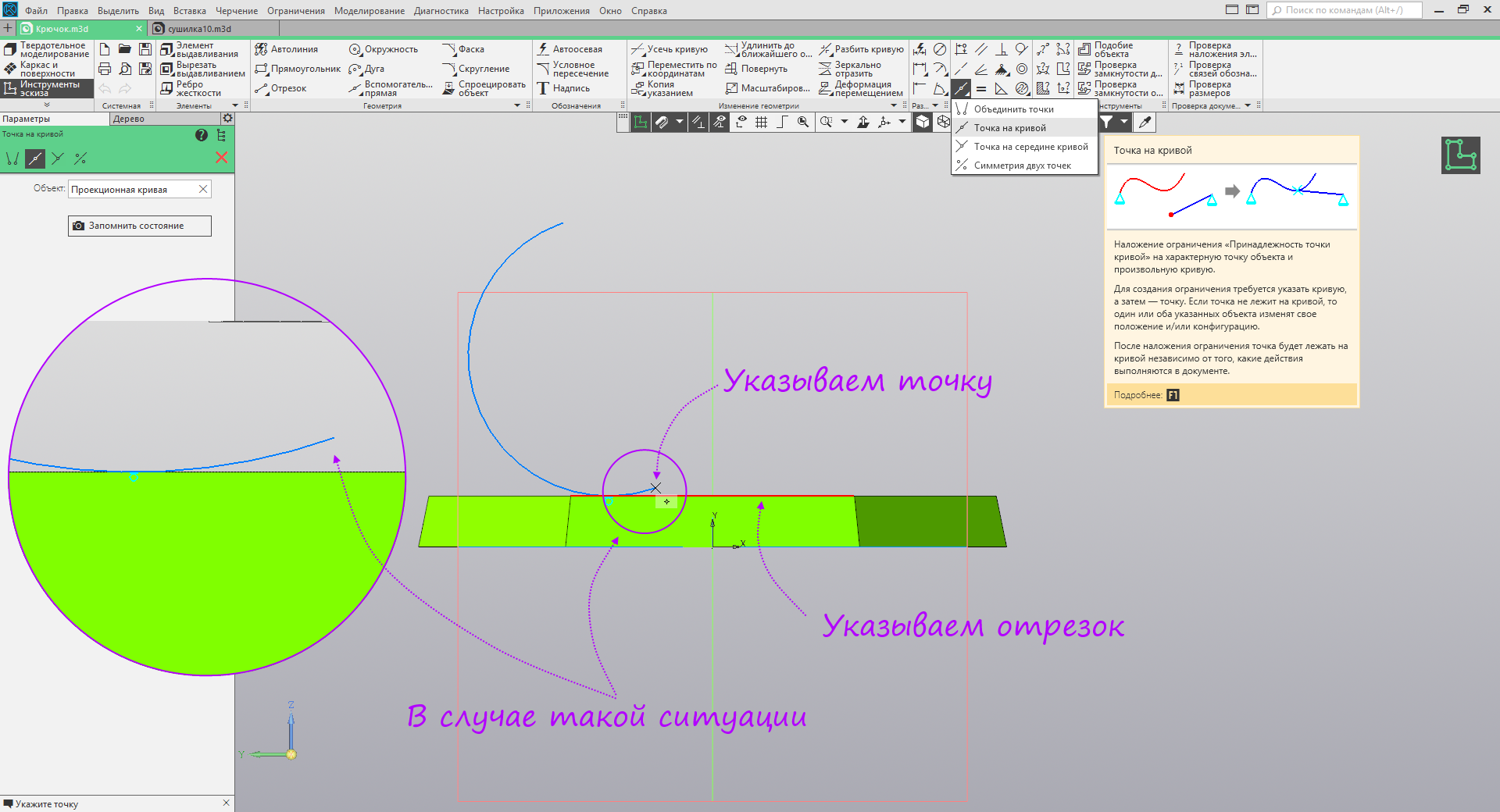
- If the end of the arc is detached from the segment, run the command Point on the curve. As a curve, we indicate the segment to which the arc is tangent, and as the point, the lowest point of the arc.
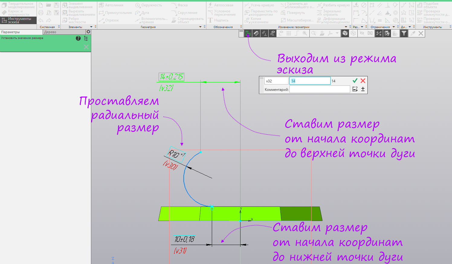
- Run the Avtorazmer command.
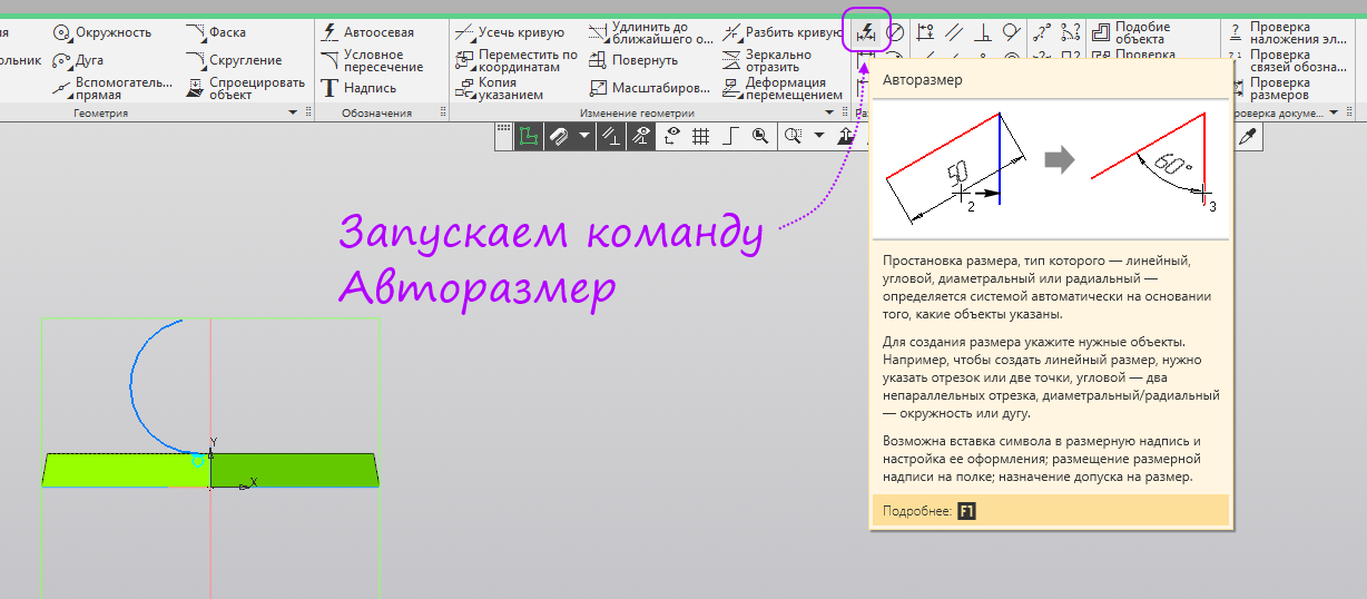
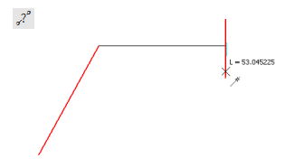
- Put down the radial size, set the horizontal dimensions from the origin to the beginning and end of the arc. Exit sketch mode.
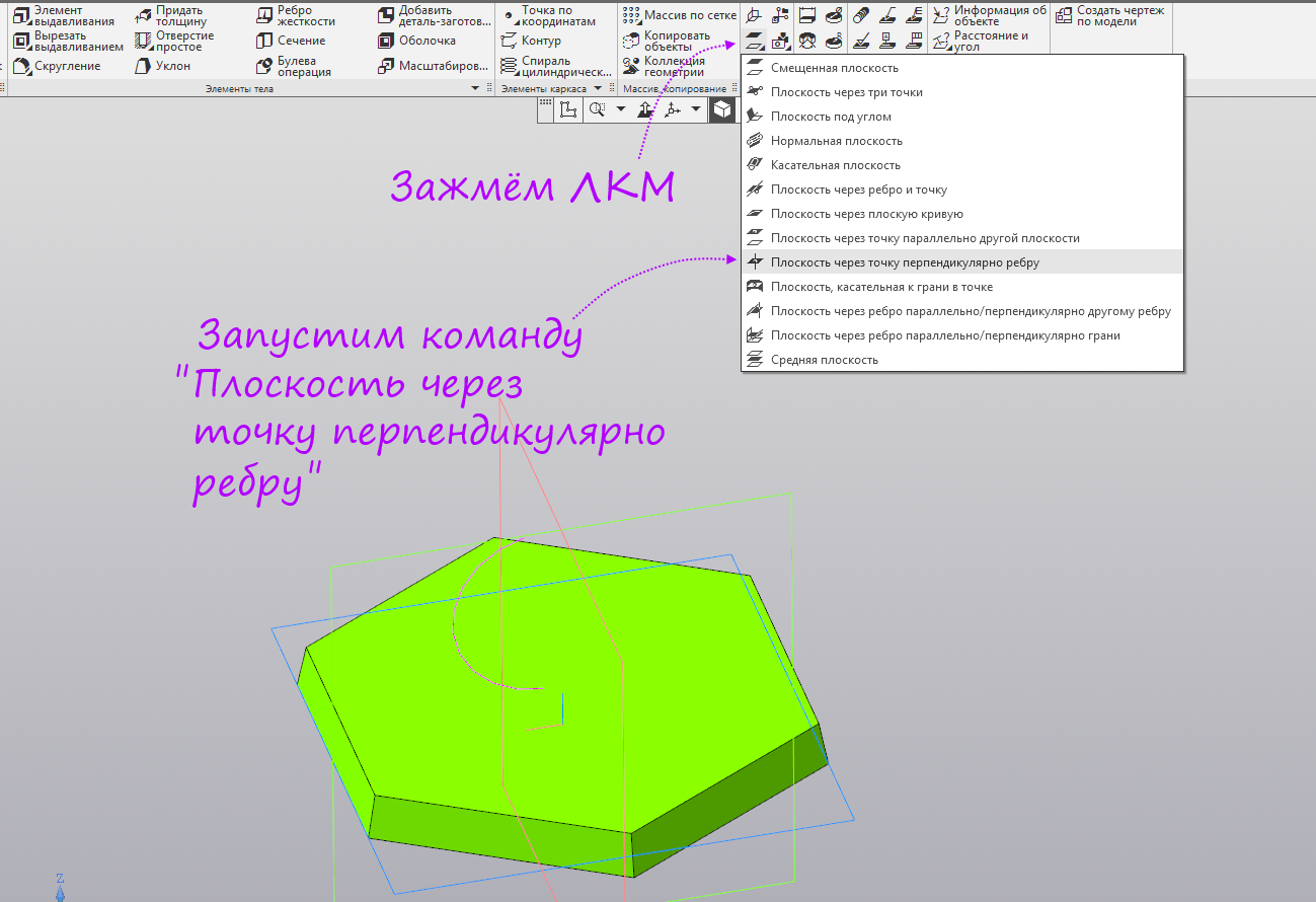
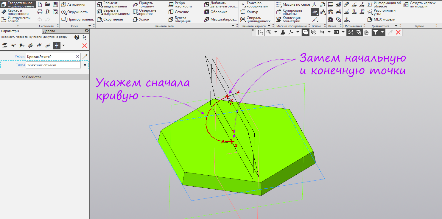
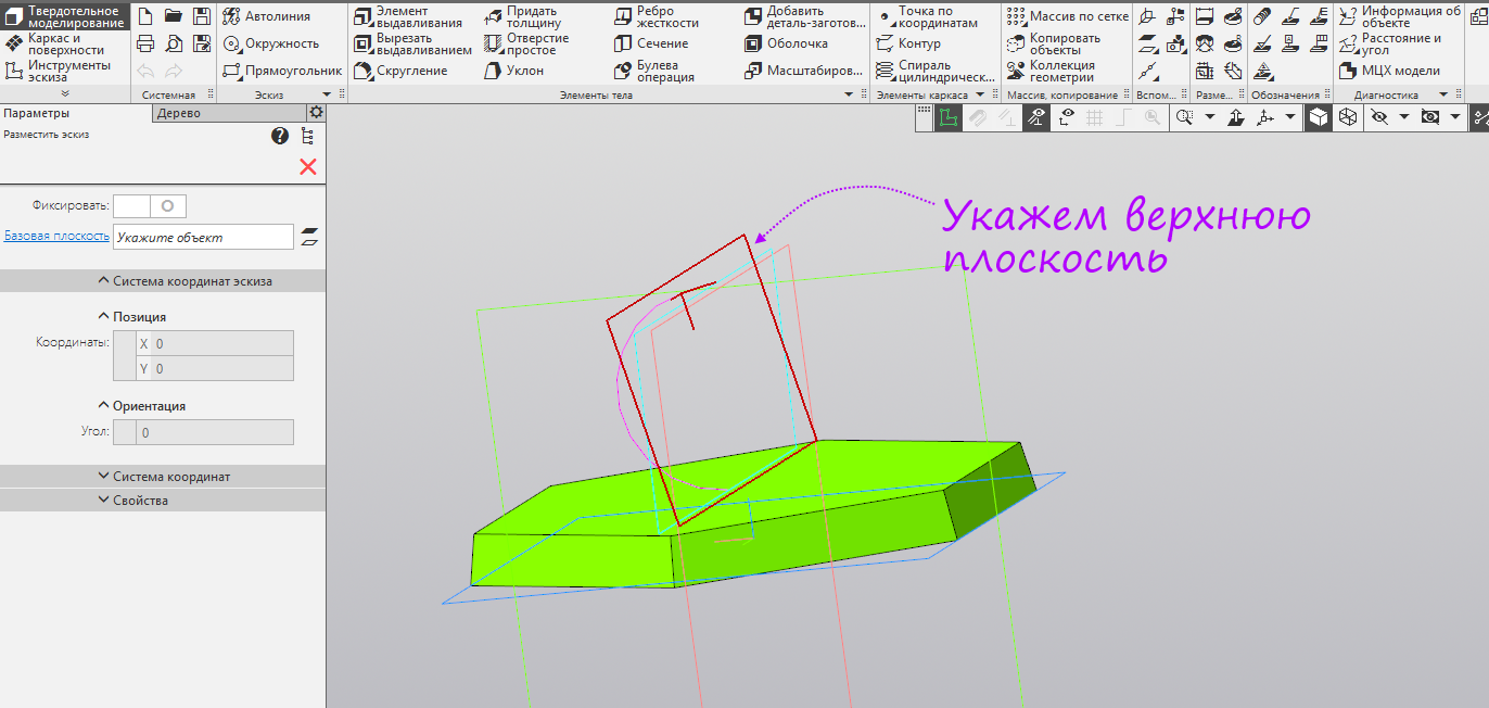
- Clamp the left mouse button on the “Offset plane” command group, in the opened panel select “Plane through a point perpendicular to the edge”.
- Specify the arc, then the starting point of the arc - created a plane. Without interrupting the command, we again specify the arc and the end point of the arc - the second plane was created.
- Without interrupting the previous command, run the Circle command.

- Specify the top plane.
- Specify the origin and enter the diameter of 4 mm. Exit sketch mode.
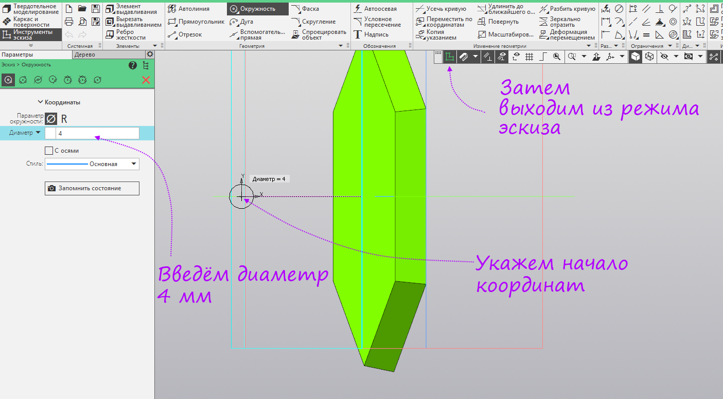
- Run the Circle command again.
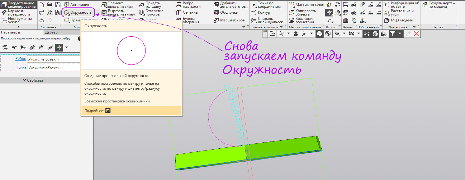
- Specify the bottom plane.
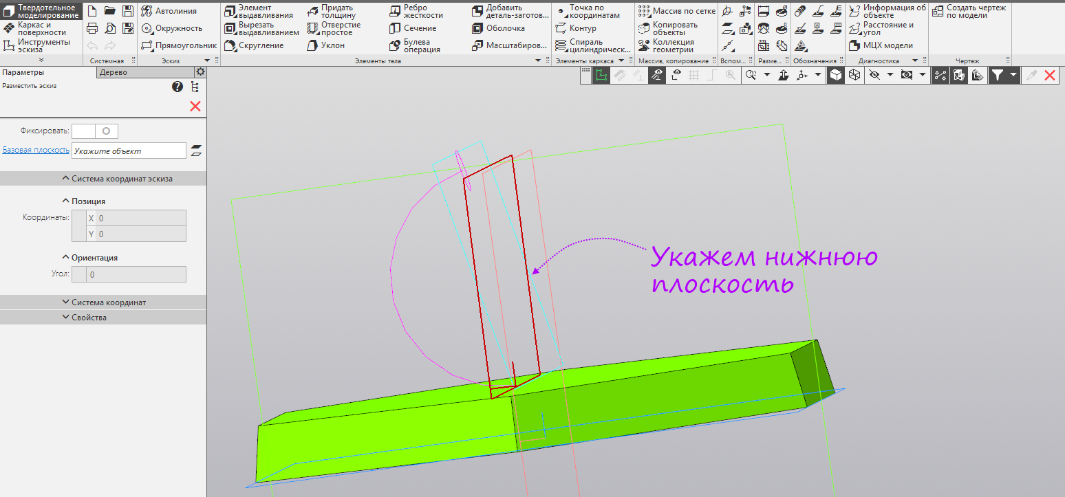
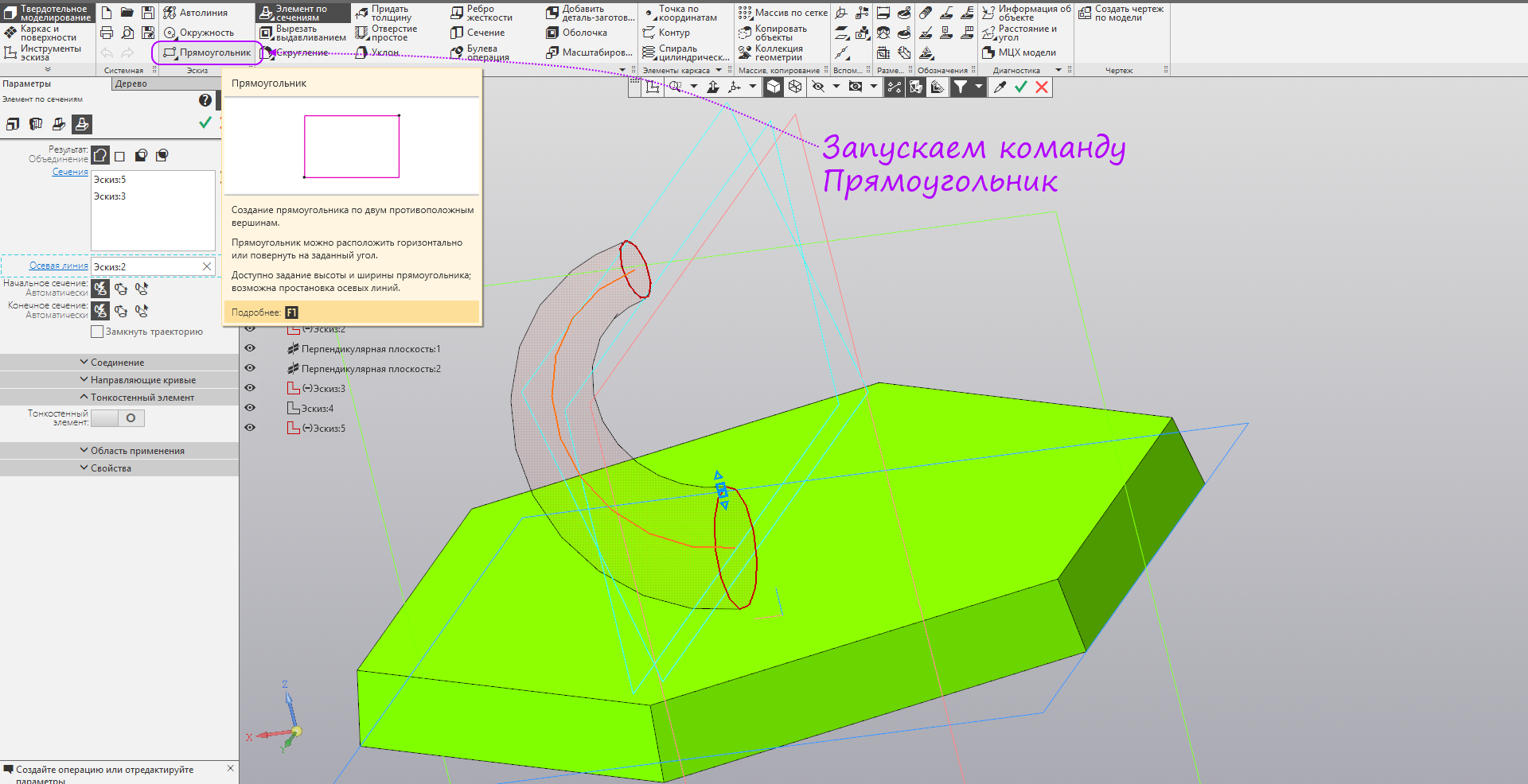
- Specify the origin and enter the diameter of 8 mm. Then we hold down the left mouse button on the “Extrusion Element” command group, in the opened panel, select “Element by sections”.

- We indicate the constructed circles as sections, and the arc as the center line.

- Without interrupting the previous command, run the "Rectangle" command.
- Select the ZY plane.
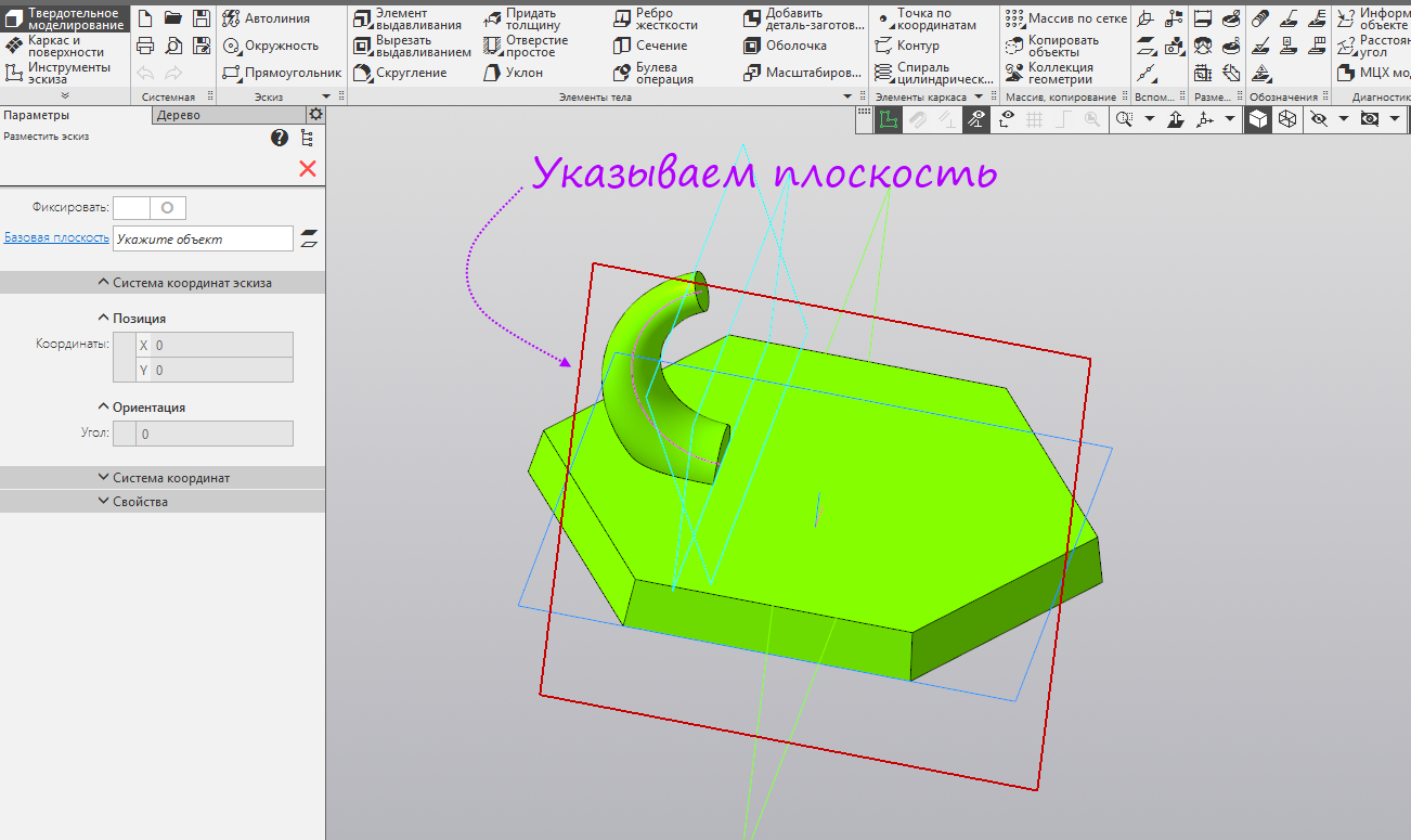
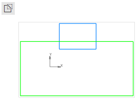
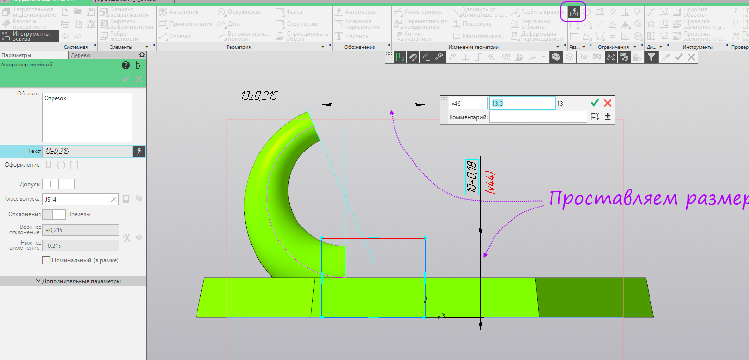
- We build an arbitrary rectangle from the origin to the side of the hook.

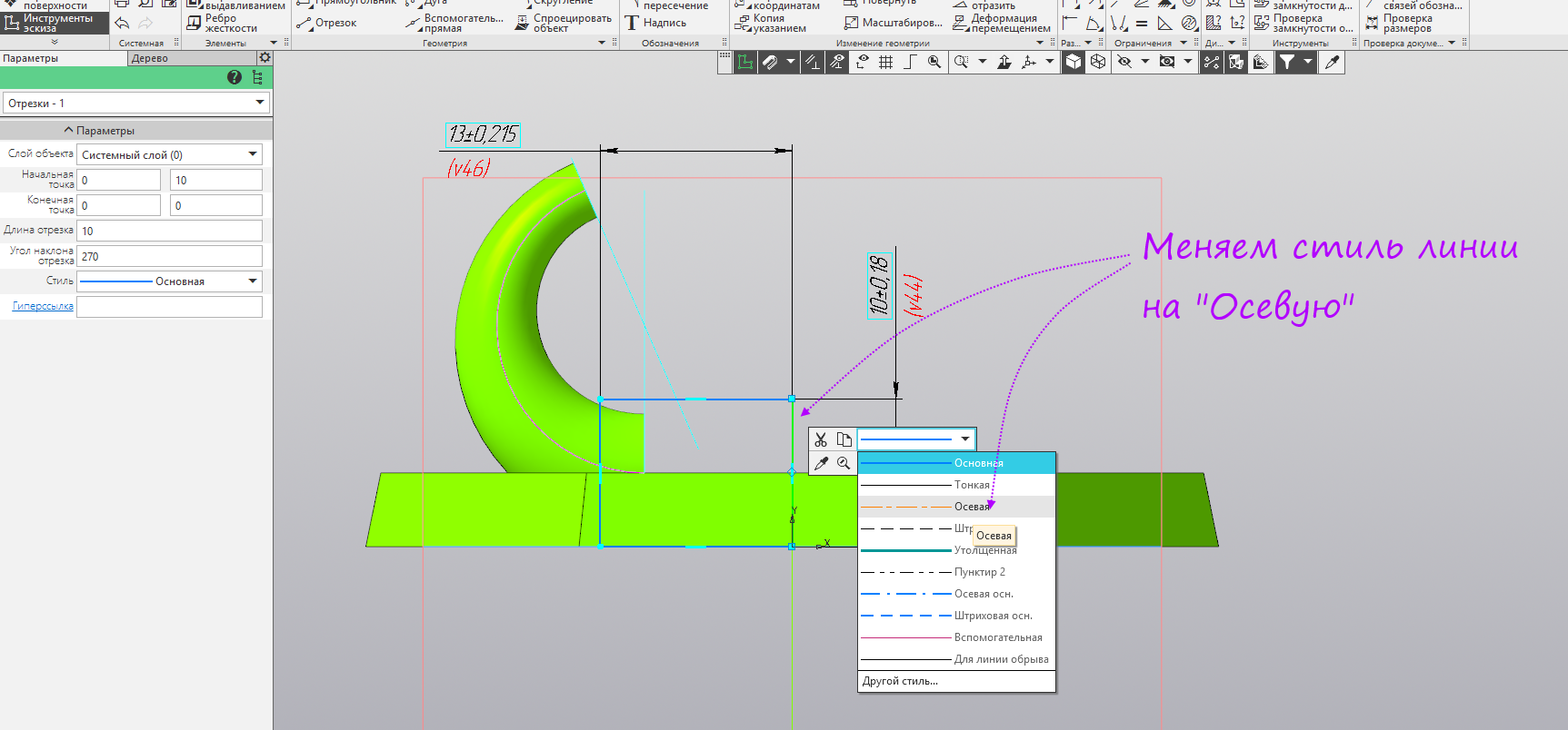
- Run the command autosize and set the size of the rectangle 10 and 13 mm.
- Change the line style at the vertical segment, leaving the origin.
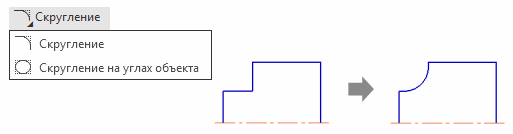
- Run the Round command.

- Set a radius of 4 mm and indicate the segments at the angle opposite to the origin.

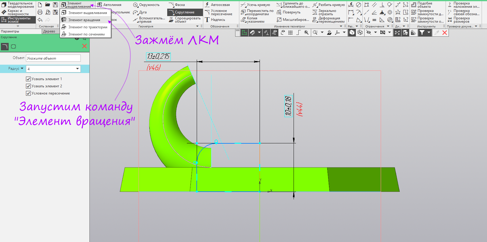
- Clamp the left mouse button on the “Extrusion Element” command group, in the opened panel, select the “Rotation Element”.
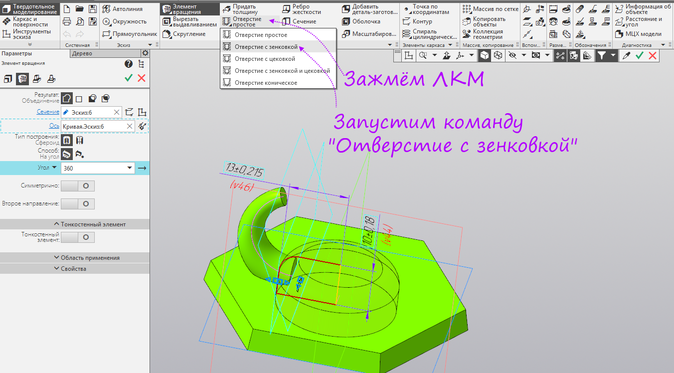
- We hold down the left mouse button on the “Hole simple” command group, in the opened panel, select “Hole with countersink”.
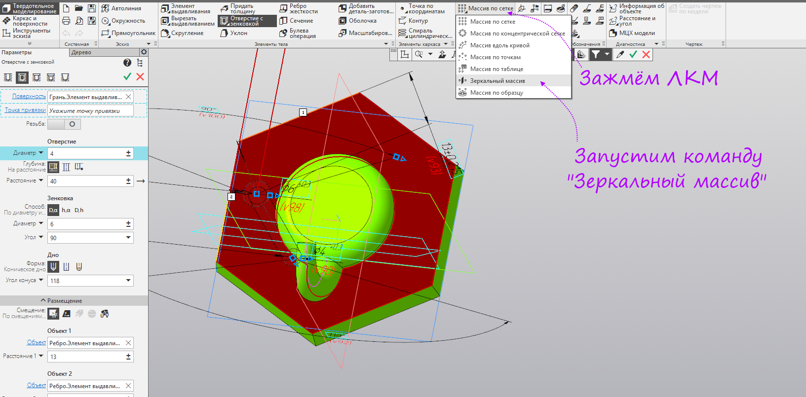
- Set the diameter of the hole - 4 mm, diameter countersink - 6 mm. We open section placement. Specify a distance of 1 - 13 mm, a distance of 2 - 6 mm.

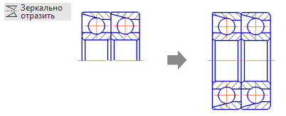
- We hold down the left mouse button on the “Array on grid” command group, in the opened panel we select “Mirror array”.
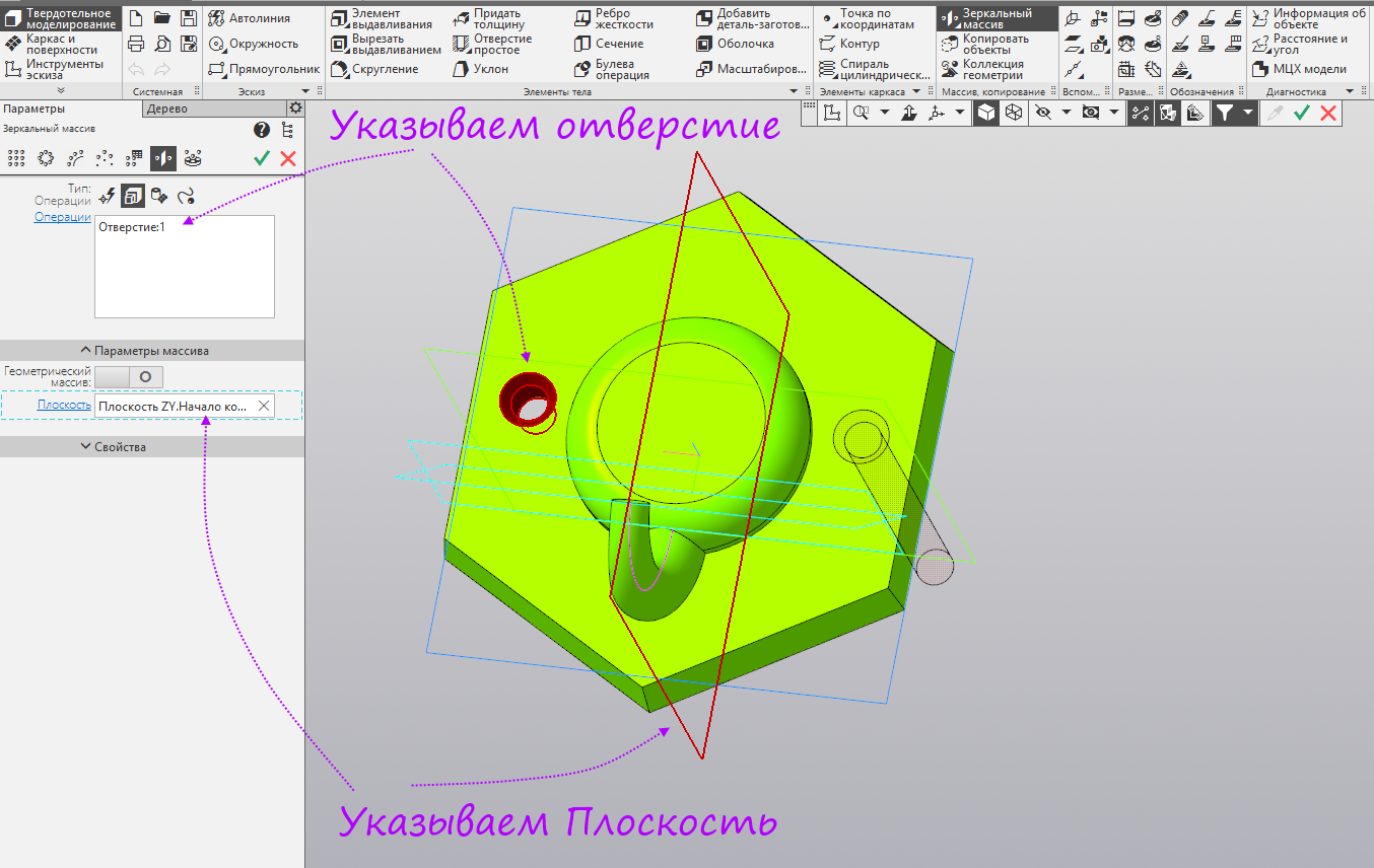
- Specify the hole and the plane ZY.
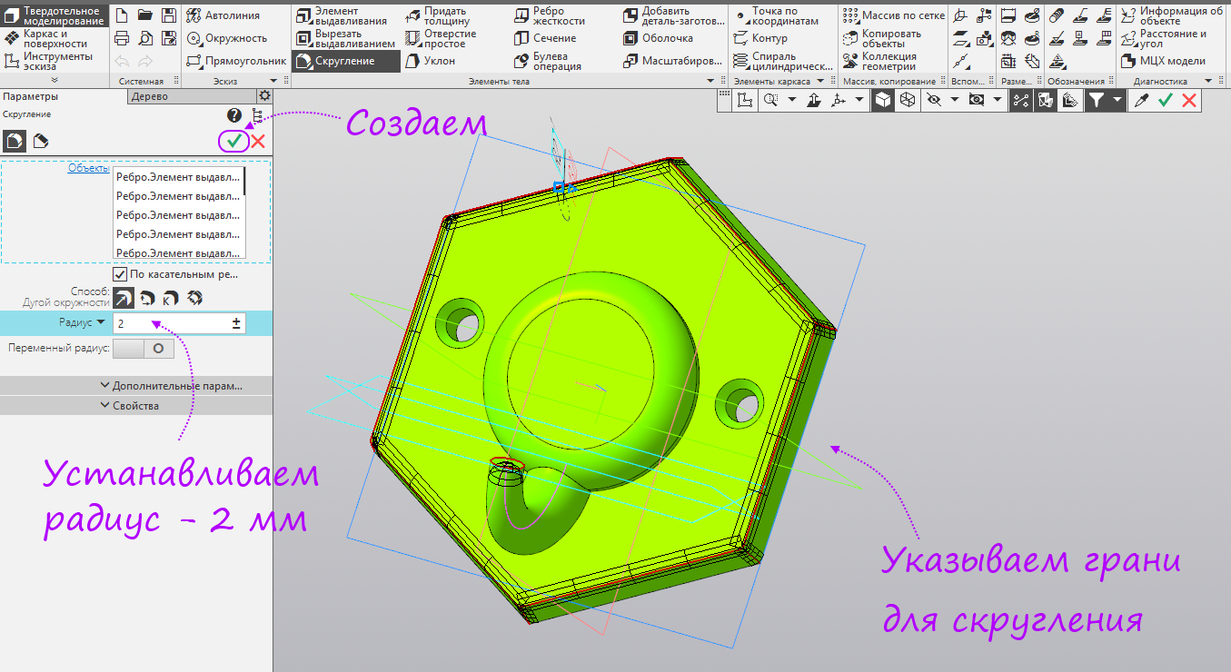
- Run the Round command.
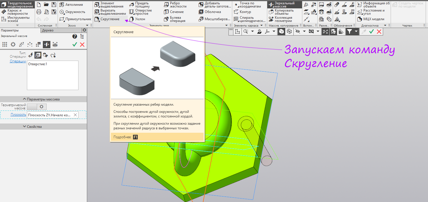
- Set the radius - 2 mm. Specify the faces that need to be rounded. Since the operation is the last, click the Create button.
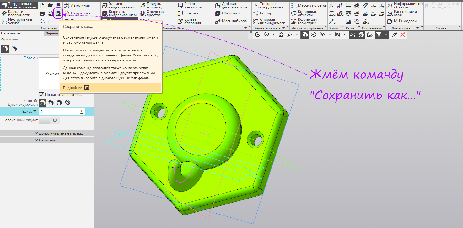
- We are preparing a model for 3D printing. Click the "Save As ..." button.
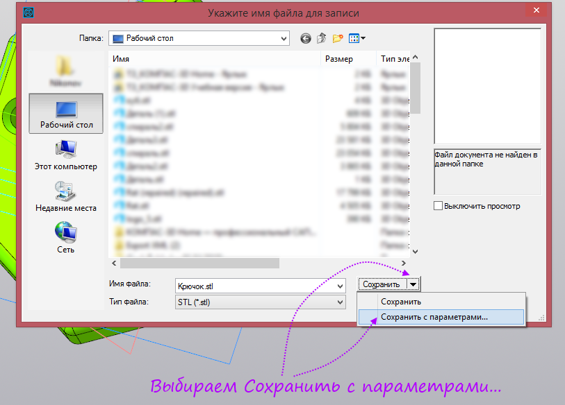
- Select the file type Stl.

- Click the triangle to the right of the Save button and select "Save with parameters ...".
- Specify the maximum angular deviation - 3 degrees and the maximum length of the edge - 5 mm. Maximum linear deviation is disabled.

- The detail is ready for 3D printing. It remains to transfer it to the printer slicer and get the g-code.

The end of the process of modeling a solid model
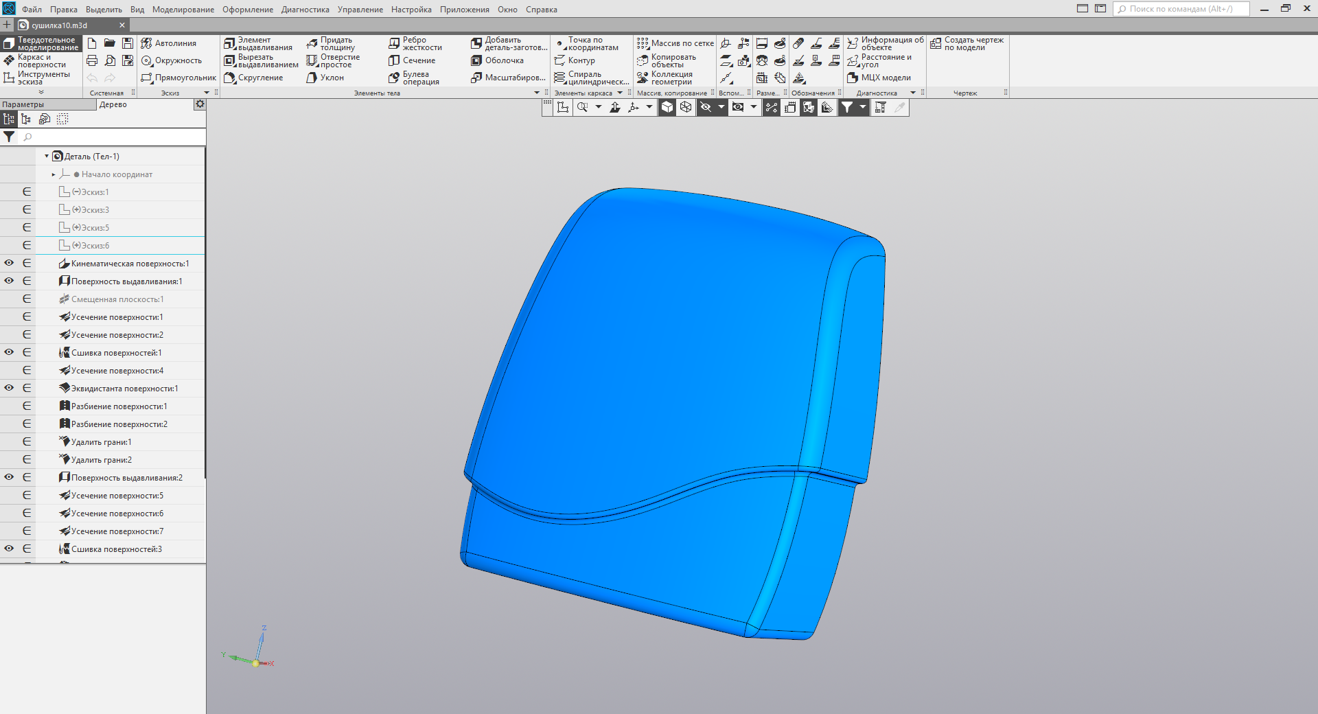
Complex case
Surface modeling process
Suppose you have developed a similar concept design of the case. You need to make it a reality.
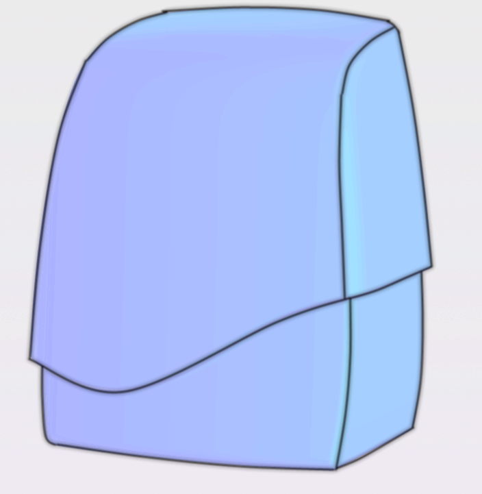
Using solid modeling, this is difficult to do because the form is complex.
At best, it will be possible to get something like this, or it will take too much effort.

We use to obtain the desired shape surface modeling.
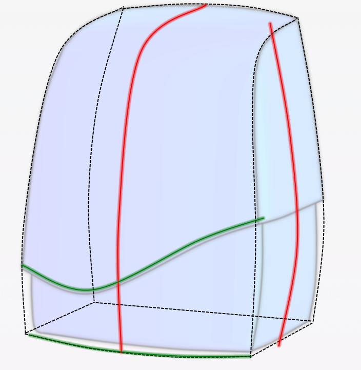
To begin with we will break the initial image into form-building elements.
Using solid modeling, this is difficult to do because the form is complex.
At best, it will be possible to get something like this, or it will take too much effort.
We use to obtain the desired shape surface modeling.
To begin with we will break the initial image into form-building elements.
- Create a part.

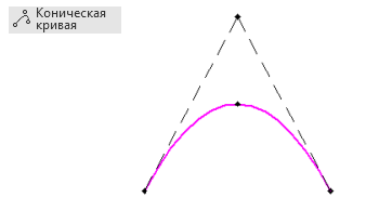
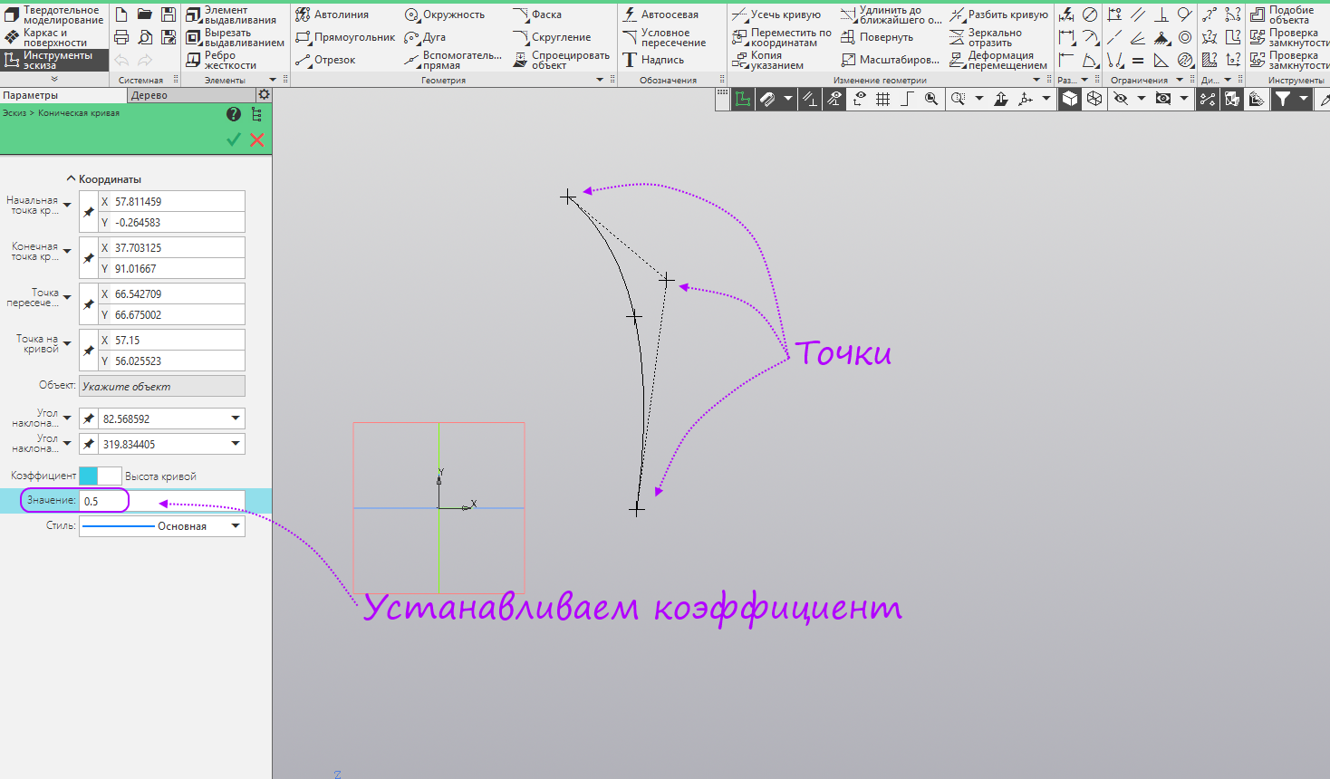
- Create a sketch in the ZY plane. Run the Conic Curve command.
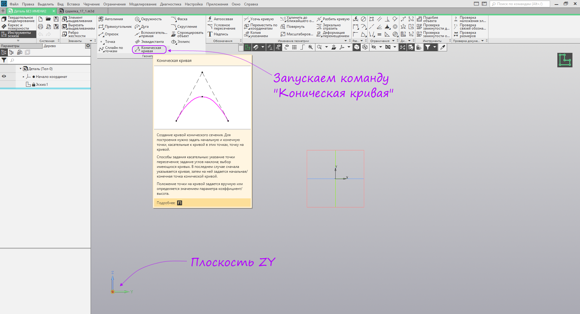
- We build an arbitrary conical curve, set the coefficient to 0.5.
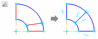
- Activate the mode of displaying degrees of freedom.

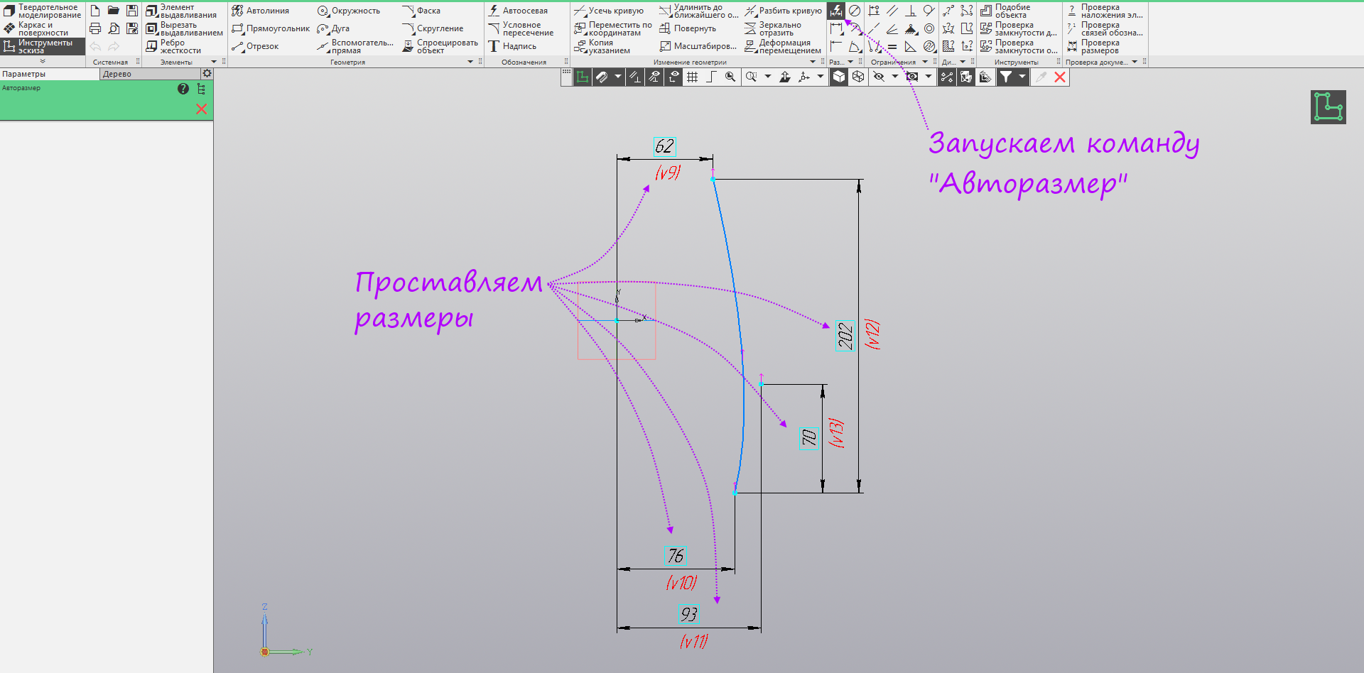
- Run the autosize command and set the dimensions as in the picture.
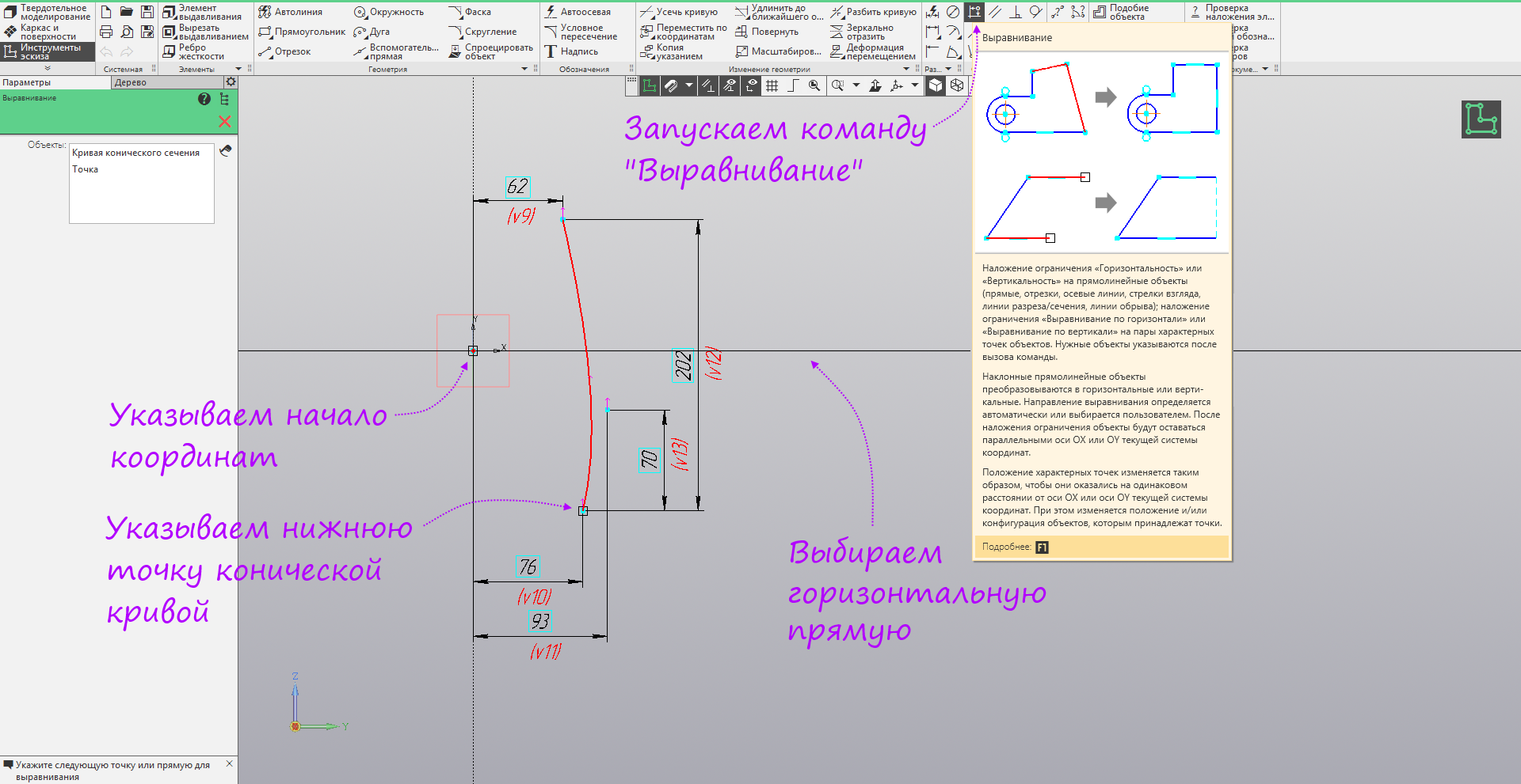
- Run the Alignment command, specify the lowest point of the conic curve and the origin, select the horizontal line to align the points horizontally.
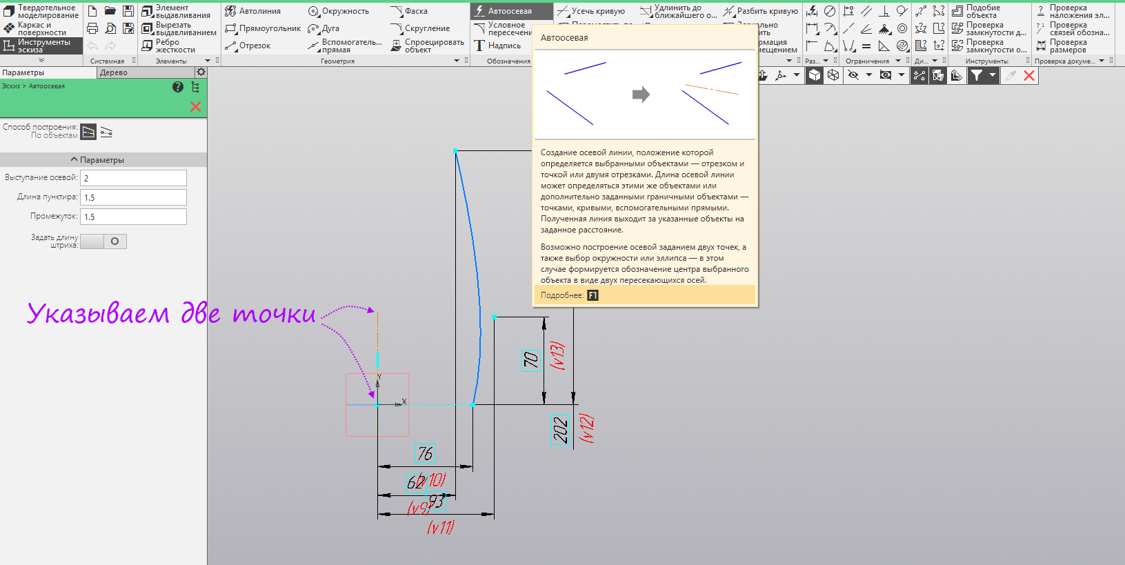
- We build a vertical auto-axis from the origin of coordinates. In the image, the size is tucked down so as not to interfere with construction.
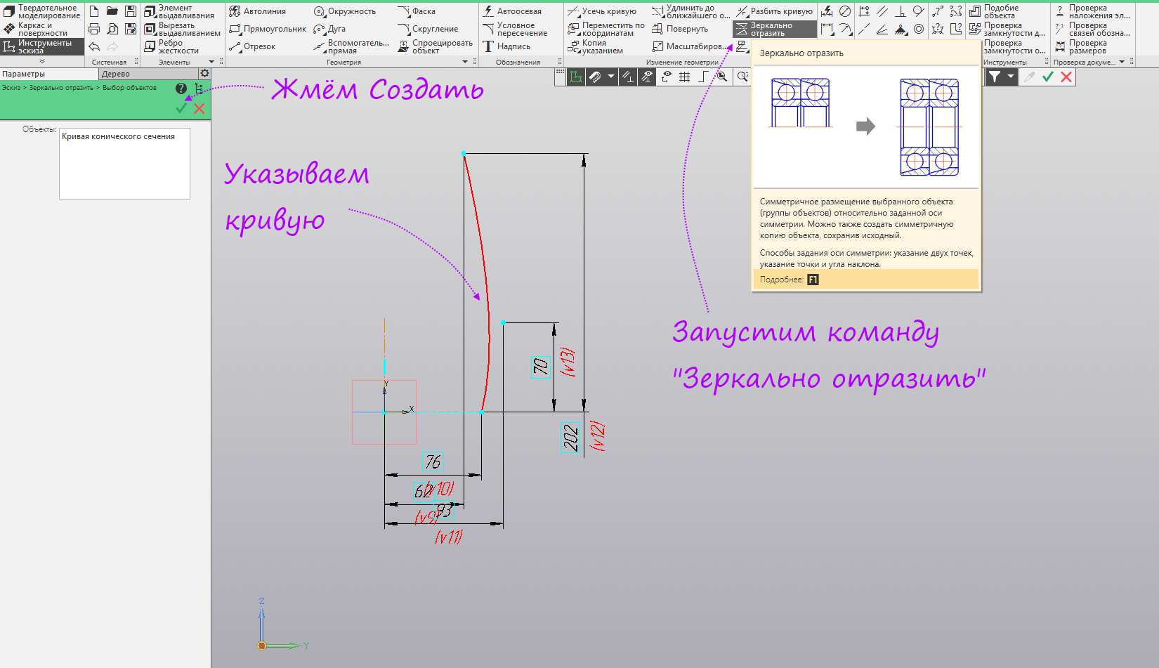
- Run the command Mirror reflection. Specify the conical curve. Click Create.
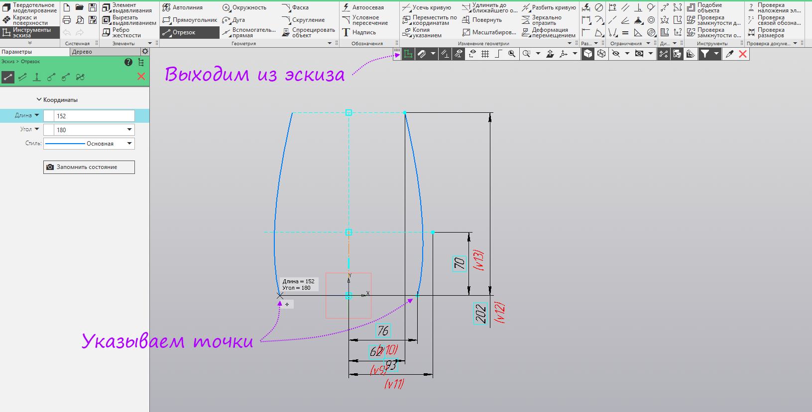
- Specify the centerline. Then run the command line.
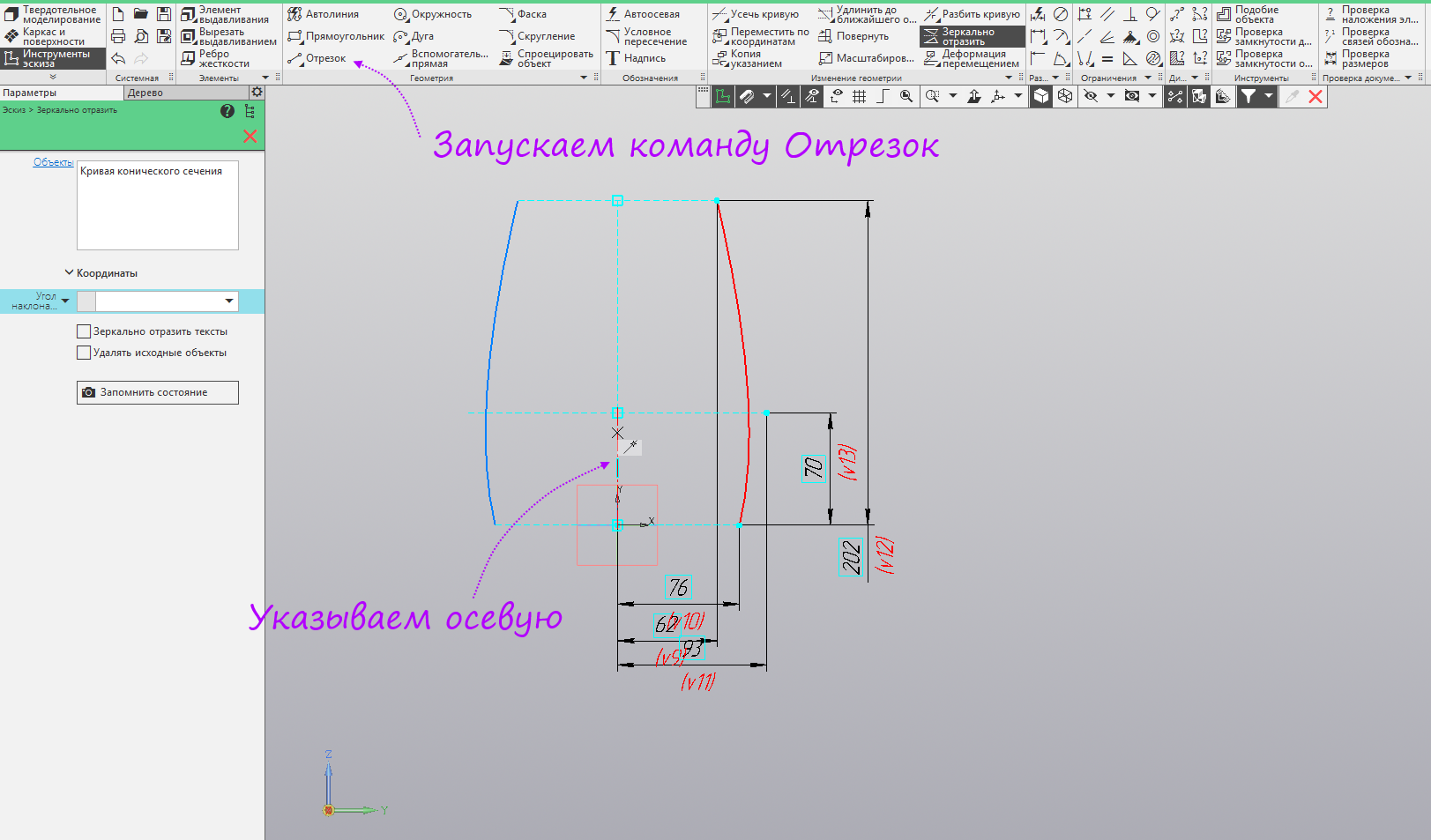
- We build a segment between the lower points of the conical curves. Exit sketch mode.
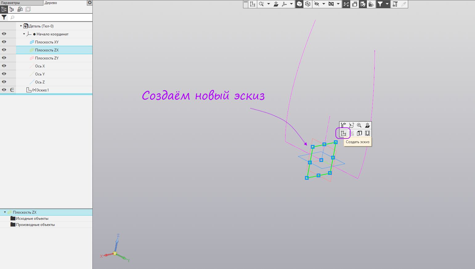
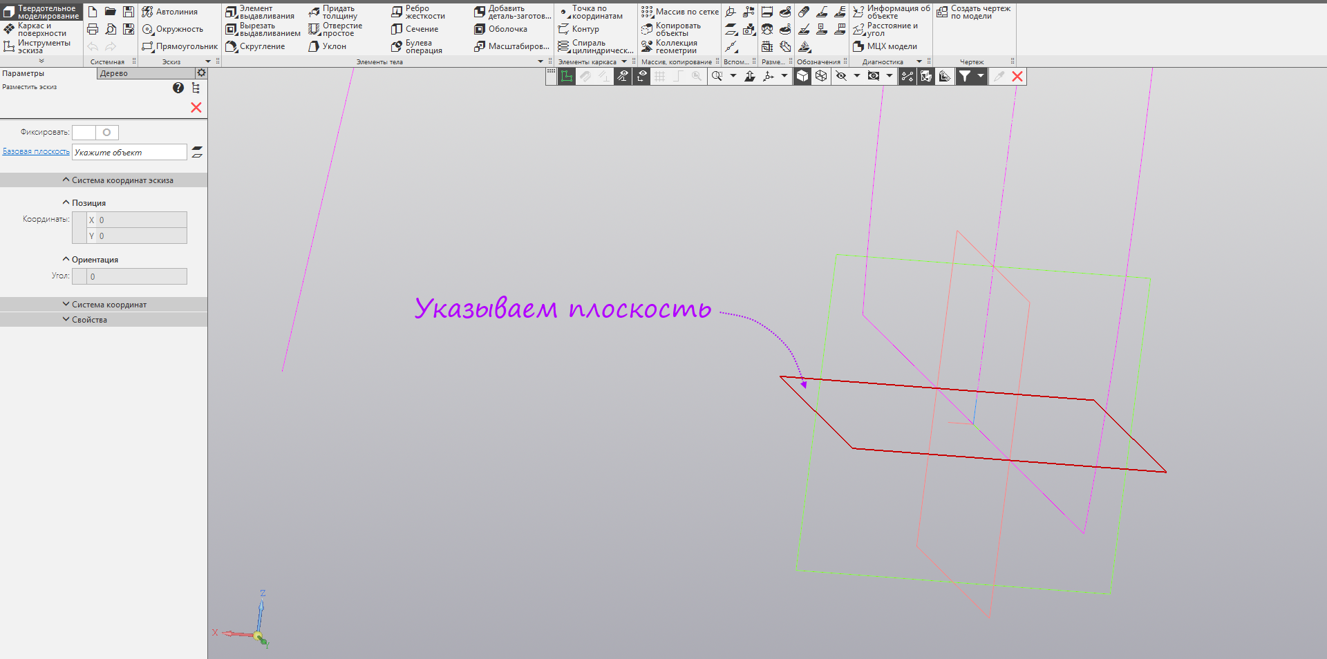
- Create a new sketch in XZ.
- Again, we build a conical curve (coefficient 0.75) and dimension the dimensions and dependencies as in the figure. Exit sketch mode.

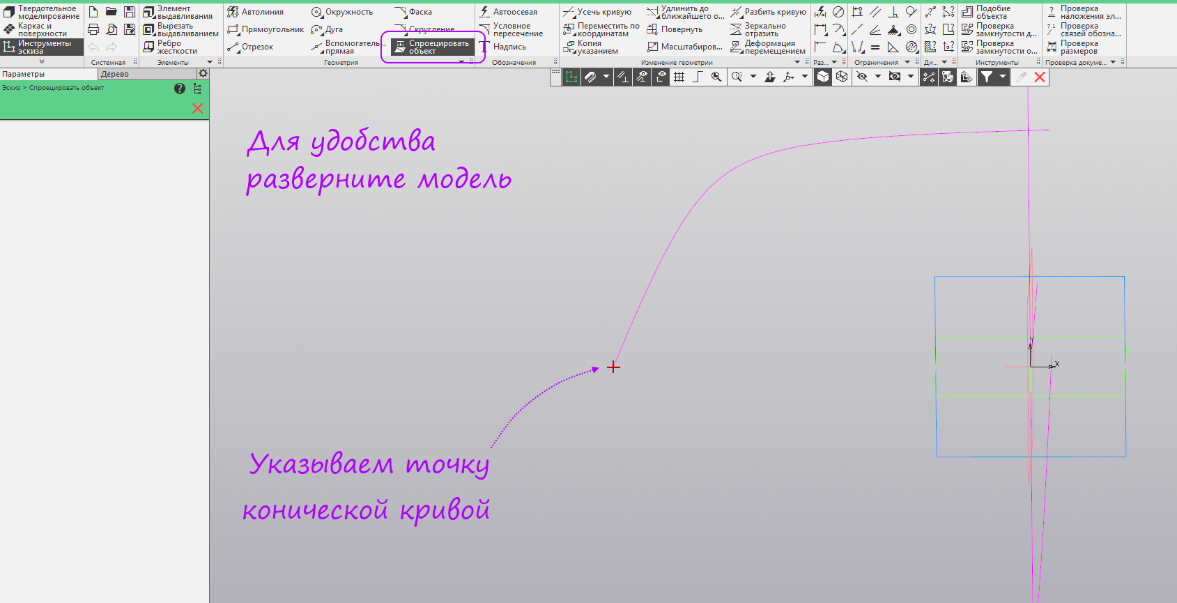
- Run the "Project Object" command.

- Specify the XY plane.
- We project into the sketch the lower point of the conical curve constructed earlier. To see the curve, it is best to expand the model using the right mouse button.
- Run the command "Spline on points". We specify 5 points so that the average coincides with the projected point. Run the Align command.
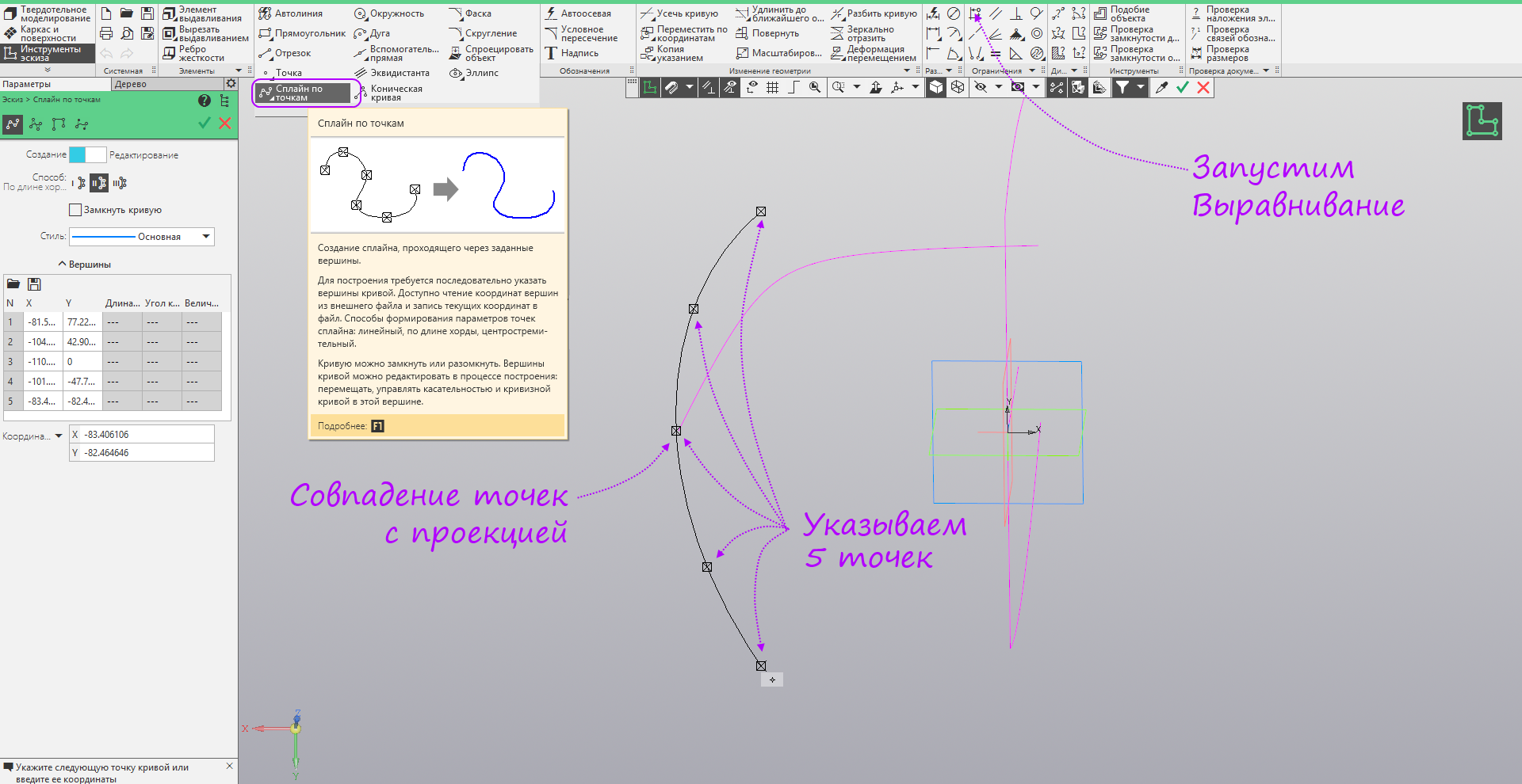
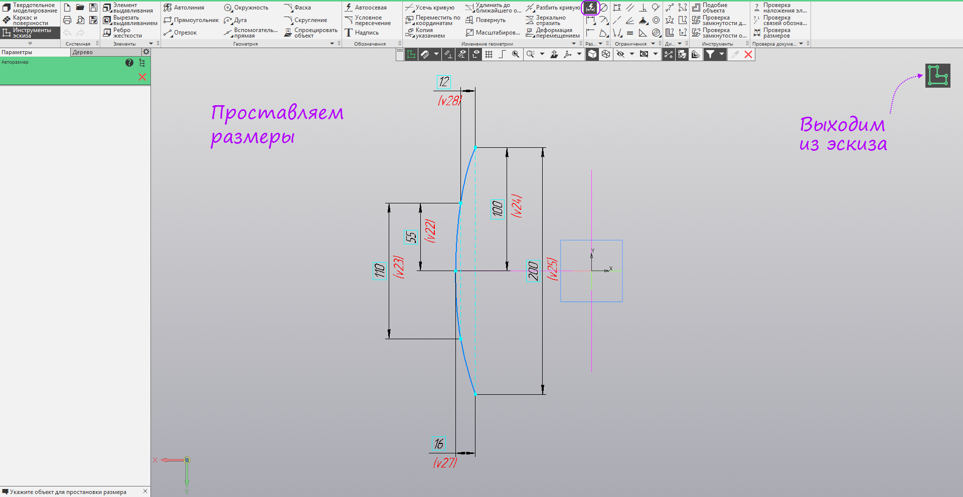
- We specify in pairs unbound points and set verticality between them. Run the Avtorazmer command.

- We put down the dimensions, as in the figure. Exit sketch mode.
- Create a new sketch in the ZY plane. Run the command "Spline Poles". We build an arbitrary spline of 7 poles. Run the command autosize.

- We put down the dimensions, as in the figure. Exit sketch mode.
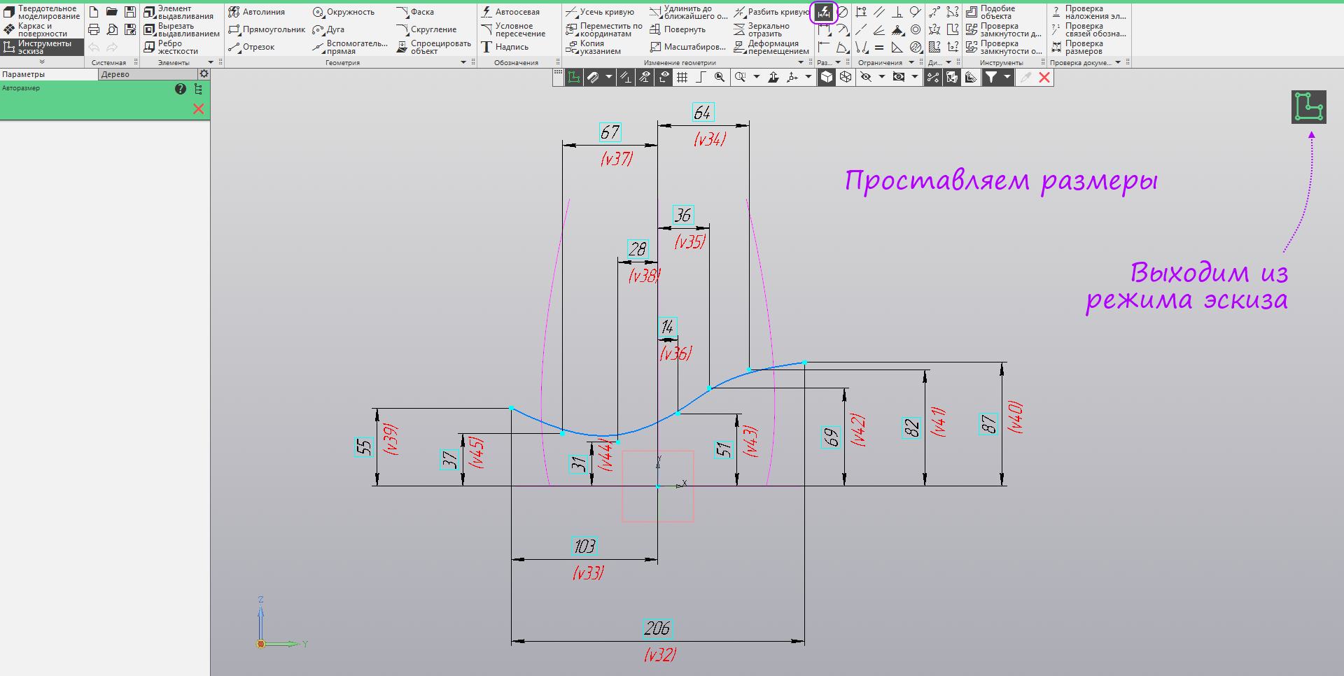
- The main shaping sketches are built - you can start building surfaces.

- Switch to the set of "frame and surface." Launch the Extrusion Surface command.
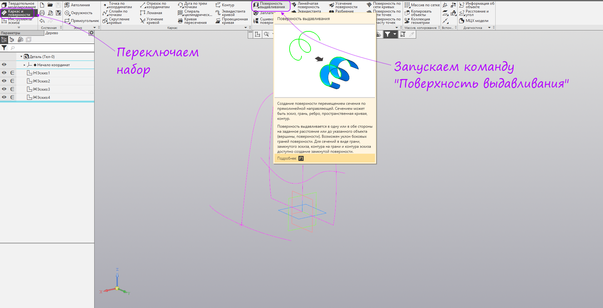
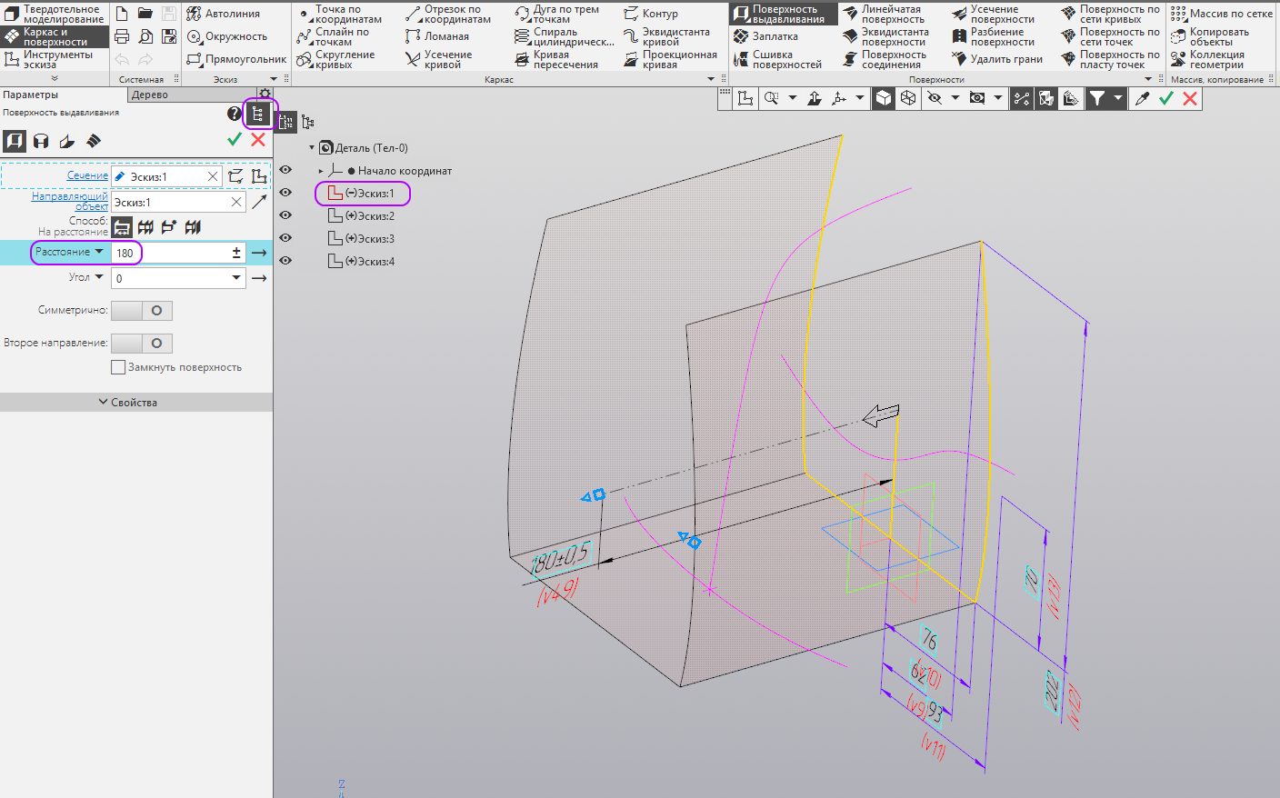
- Open the transparent tree. Select the first sketch and set the distance to 180 mm. Create an operation.
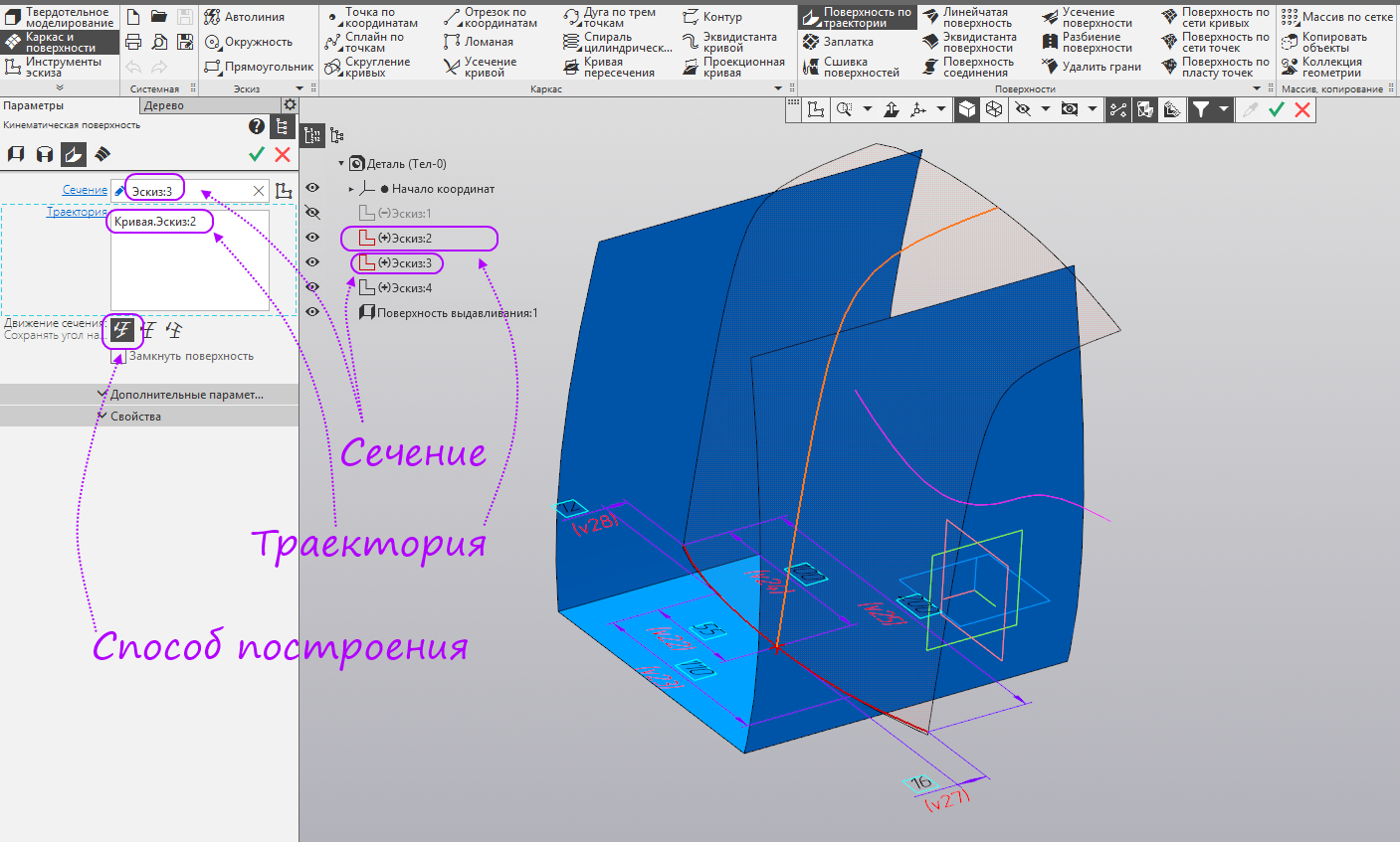
- Run the command Surface trajectory.

- We specify the third sketch as a section, and the second as a trajectory. Select the method of building the "maintain the angle of inclination." Create an operation.
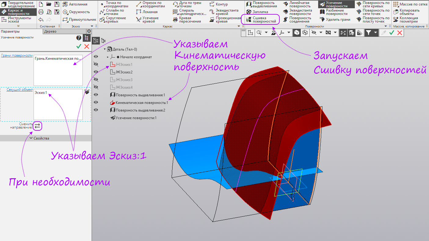
- Run the Extrusion Surface command again. Specify the fourth sketch and a distance of 200 mm. Run the command Trim the surface.
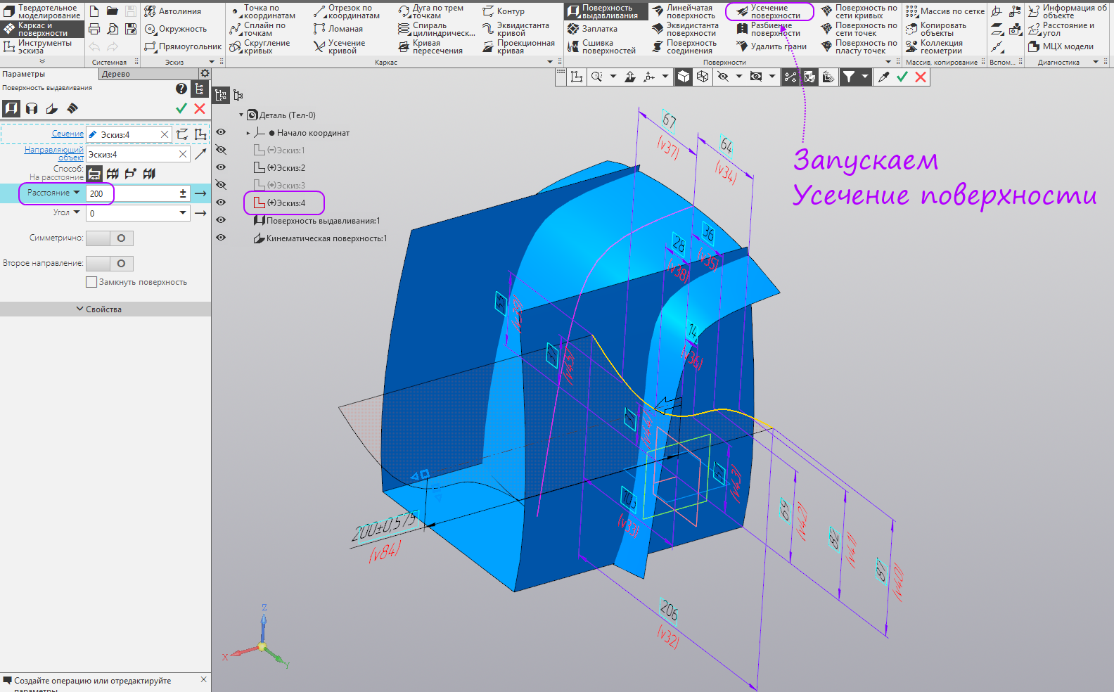
- Specify the extrusion surface in the tree. Switch to a segmented object - specify the kinematic surface. If necessary, change the direction so that the part forming the surface we need remains. Create an operation.

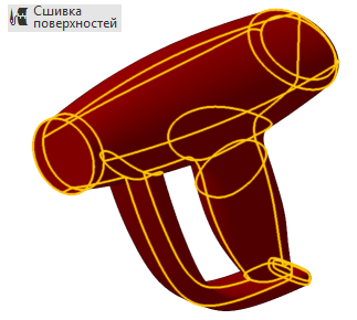
- Select the kinematic surface and the first sketch as a cutting object. If necessary, change the direction so that the part forming the surface we need remains. Run the command Surface sewing.
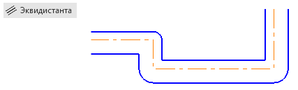
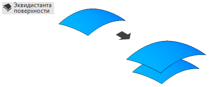
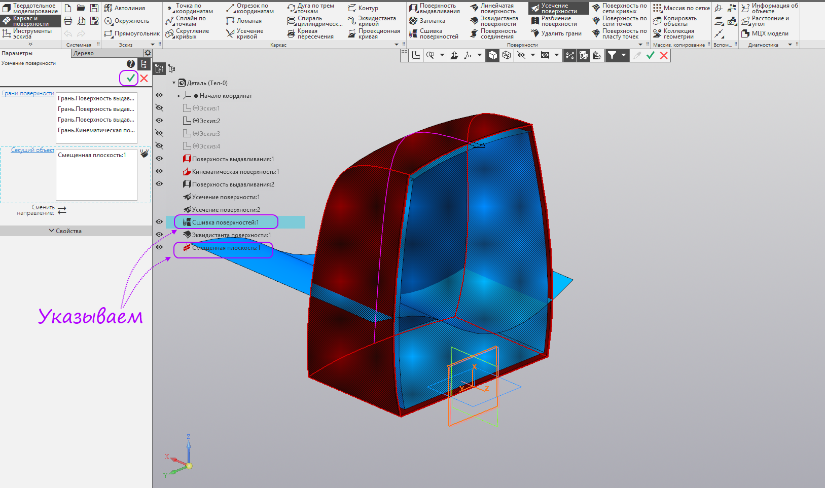
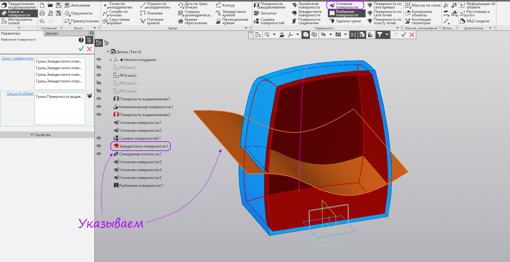
- We indicate the parts of the kinematic surface and the extrusion surface remaining after truncation. Run the command Equidistant surface.

- Specify the stitching of surfaces in the tree. When creating equidistants, edge effects inevitably appear. They need to be cut off. Run the offset plane to create a truncation.

- We build the displaced plane at a distance of 2 mm in the direction of the surfaces. Run the command Trim the surface.

- Specify the stitching of surfaces and the displaced plane as a clipping object. If necessary, change the direction so that the part forming the surface we need remains. Create an operation.
- Specify the equidistant surface and the displaced plane as a clipping object. If necessary, change the direction so that the part forming the surface we need remains. Create an operation.
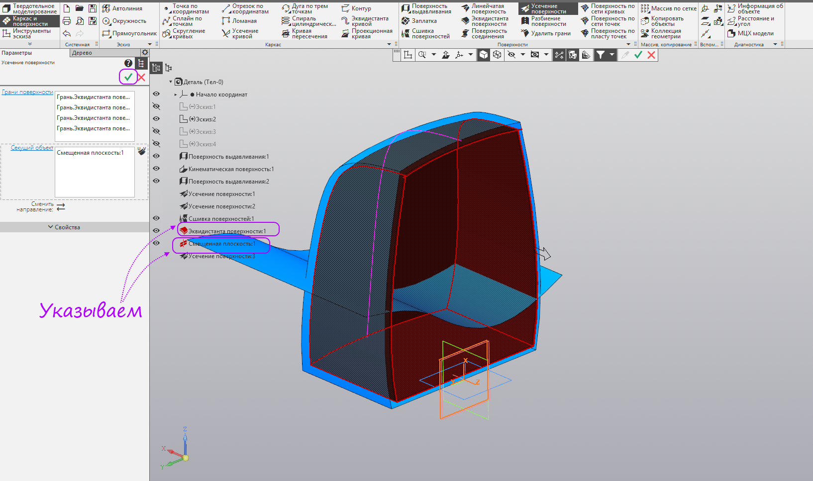
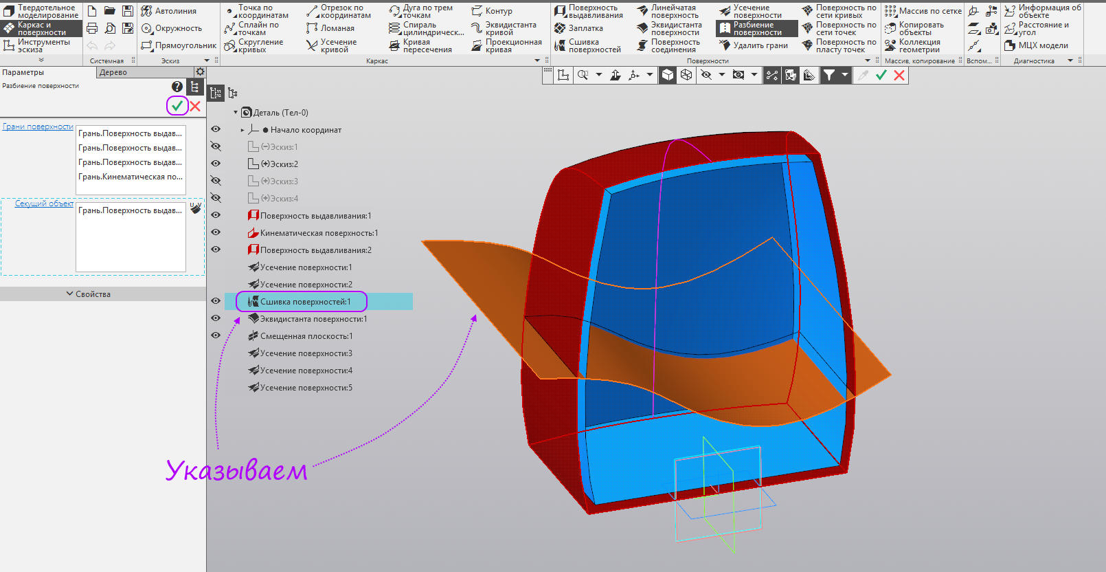
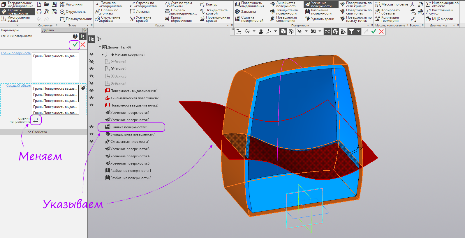
- Specify "Extrusion Surface: 2" and the offset plane as a cutting object. If necessary, change the direction so that the part forming the surface we need remains. Run the Split Surface command.

- We specify in the tree the merging of surfaces and in the “Extrusion Surface: 2” model window as a clipping object. Create an operation.
- We specify in the tree the equidistant of the surface and in the model window "Surface extrusion: 2" as a clipping object. Run the command Trim the surface.
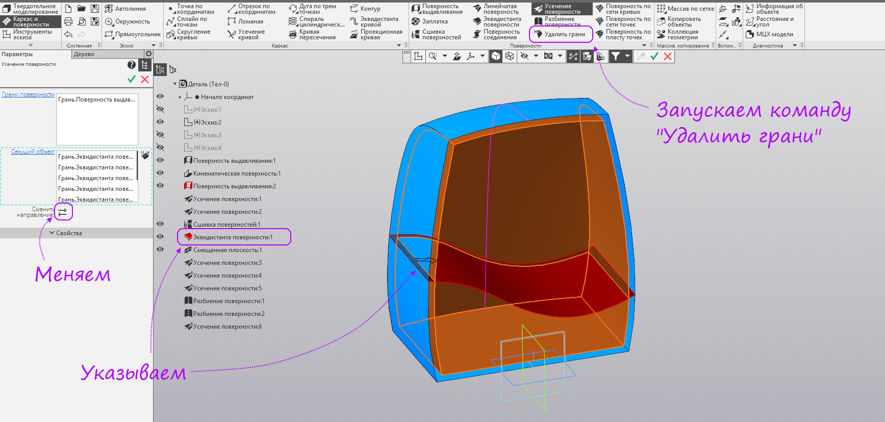
- We indicate in the model window “Extrusion surface: 2” and in the tree the merging of surfaces as a clipping object. If necessary, change direction, to remain the inner part. Create an operation.
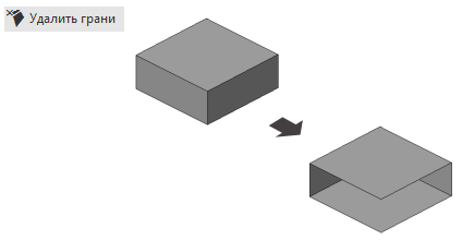
- We indicate in the model window the remaining part of the extrusion surface and in the tree the surface equidistant as a clipping object. If necessary, change the direction so that there is a part between the stitching and equidistant. Run the command "Delete Faces".
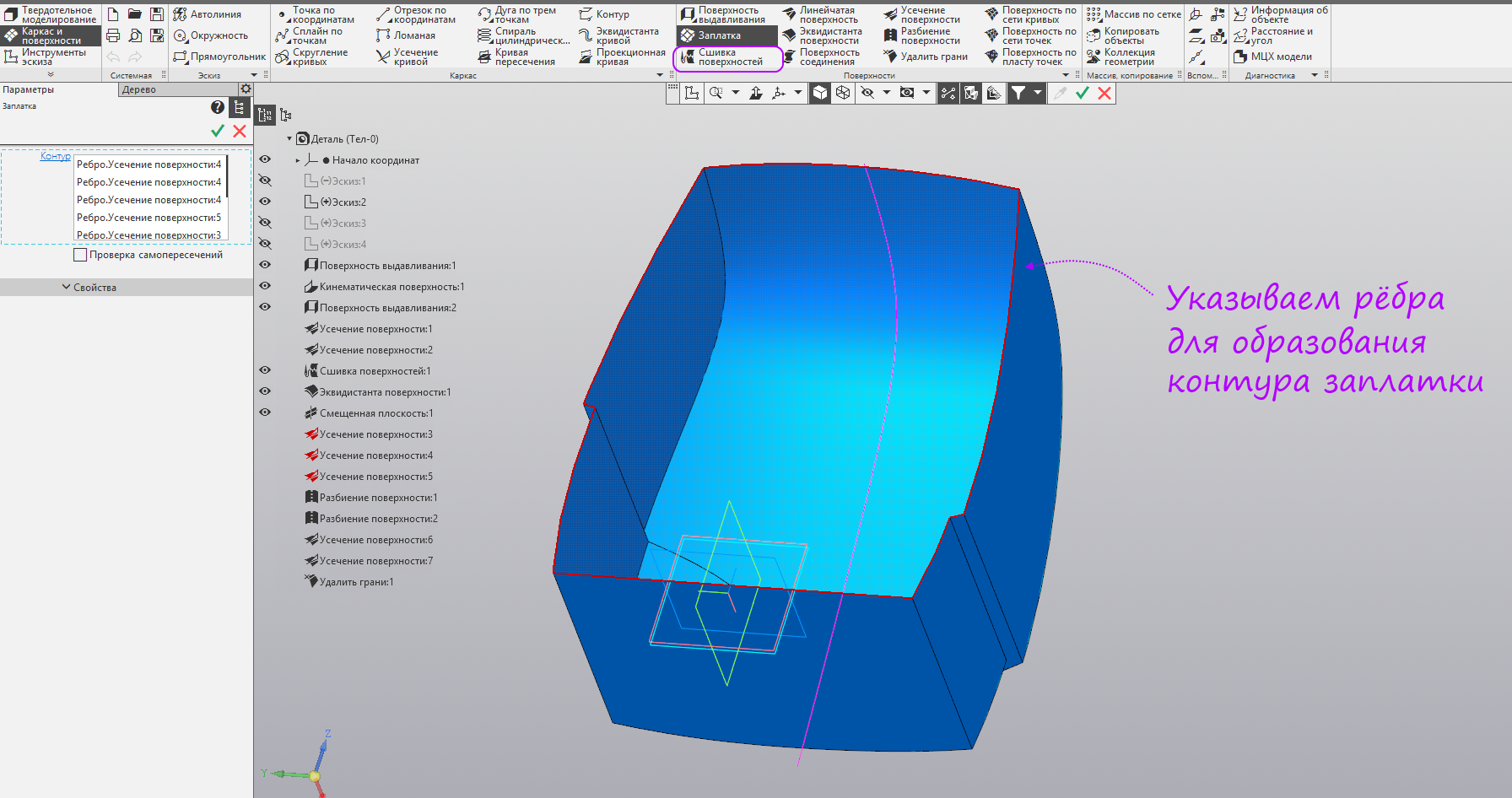
- We indicate three inner faces (equidistants) on the top and four outer faces (stitches) on the bottom. Run the patch command.
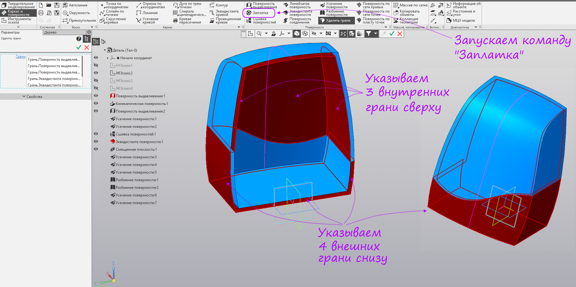
- Specify the surface edges to form a patch outline. Run the command Surface sewing.
- We indicate in the tree the surface stitching, the surface equidistant, “Extrusion surface: 2” and the patch. Create an operation.

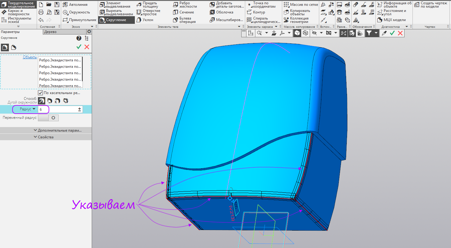
- Switch to the "Solid Modeling" set. Run the Round command. Set the radius of 11 mm, specify the edges, as in the figure. Create an operation.

- Set a radius of 6 mm, specify the edges, as in the figure. Create an operation.
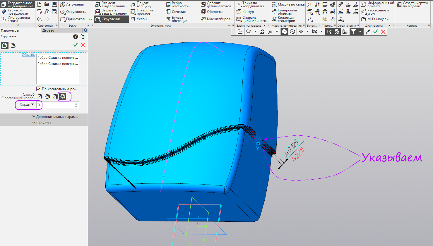
- Switch to the method with a constant chord. Set a radius of 3 mm, specify two edges, as in the figure, the rest are allocated automatically, because the rounding is extended along the tangent edges. Run the shell command.
- Specify a flat face (the team can remove only flat faces). Set the shell thickness of 3 mm (shell thickness can not be more than the smallest radius in the model). Create an operation.
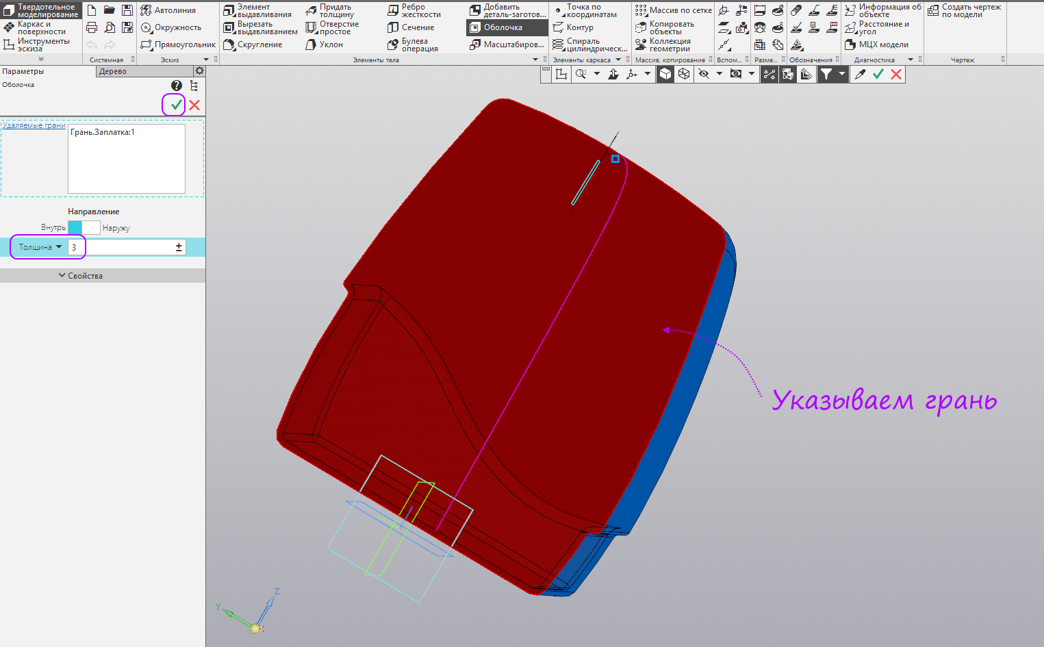
- It turned out such a body. It remains to supplement it with fasteners for internal structures and the rear.

End of surface modeling description
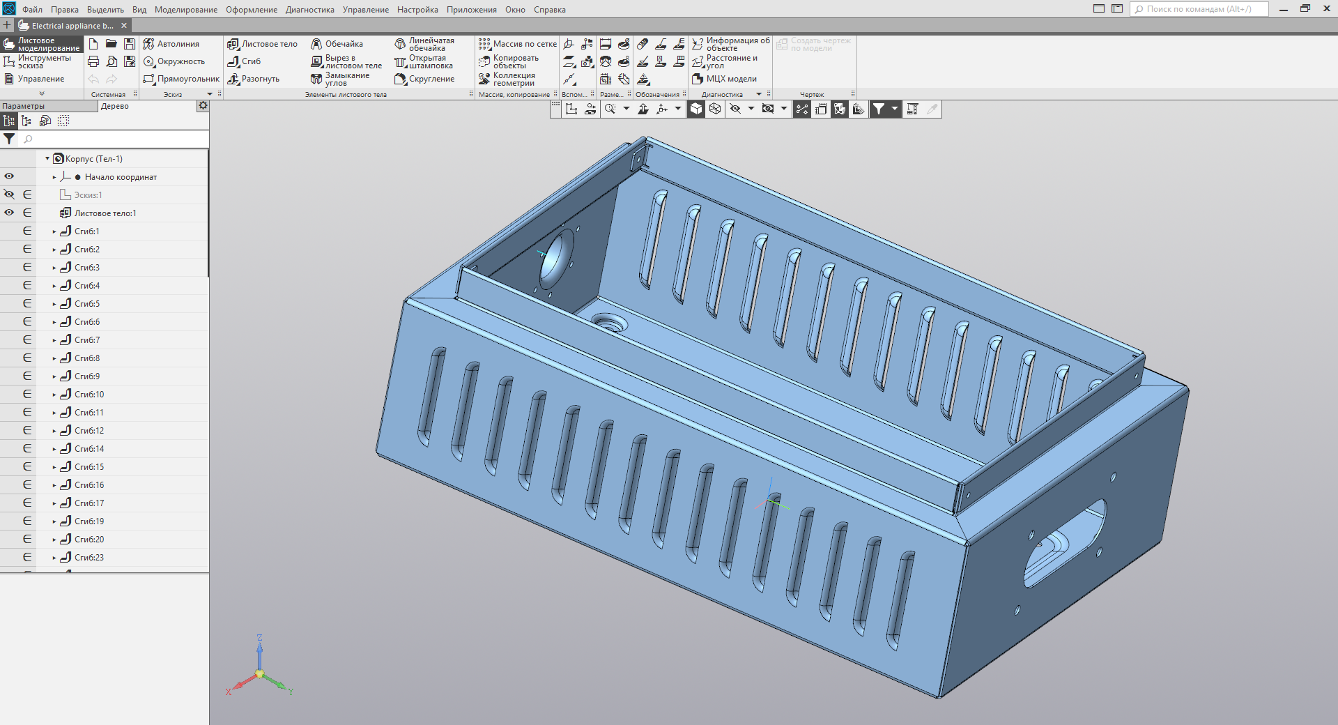
Sheet metal housing
Leaf model modeling process
It is not interesting to create a banal box from a sheet - everyone will figure it out anyway, and there are a lot of video lessons. Let's try to build from the sheet an analogue of the body, which was made by surface modeling in the last lesson. Completely repeat it will not work, but at least the basic form.
4 , , DXF .
- Create a part
- For convenience, we will include the specialization sheet metal. Choose File - Specialization - Sheet Detail.
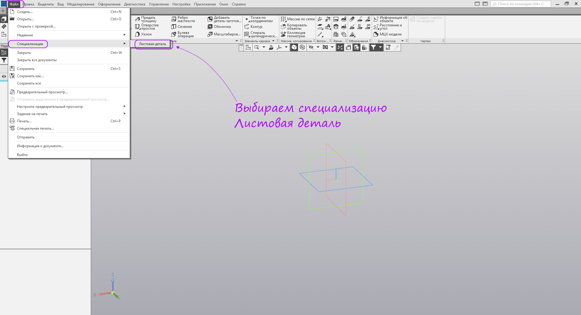
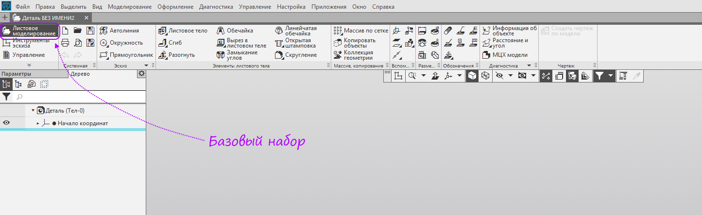
- The basic set has changed to "Sheet modeling".
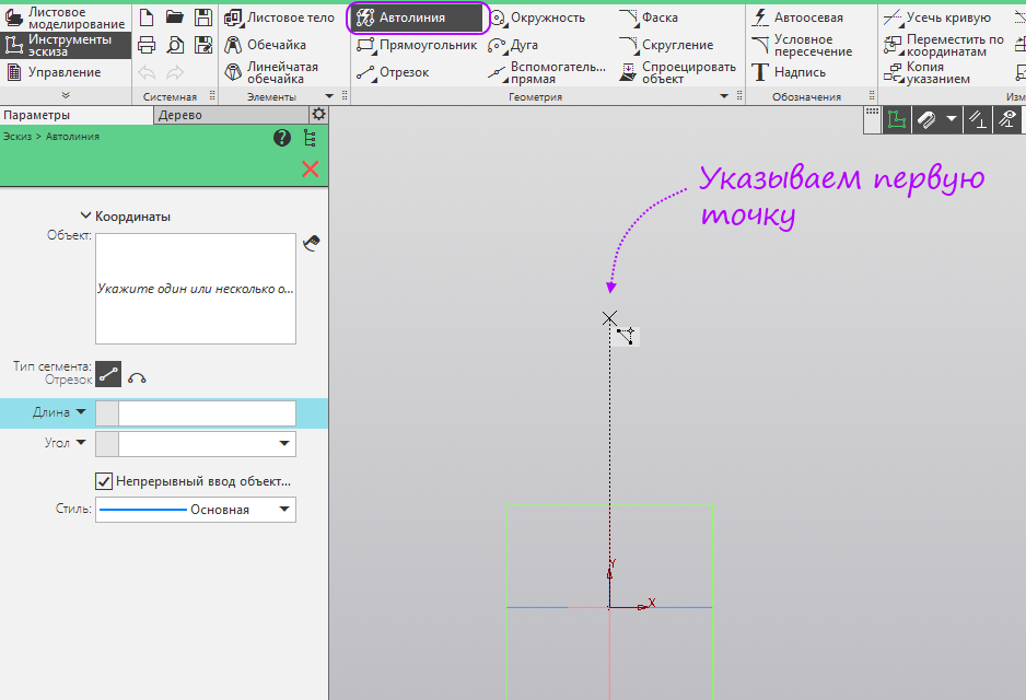
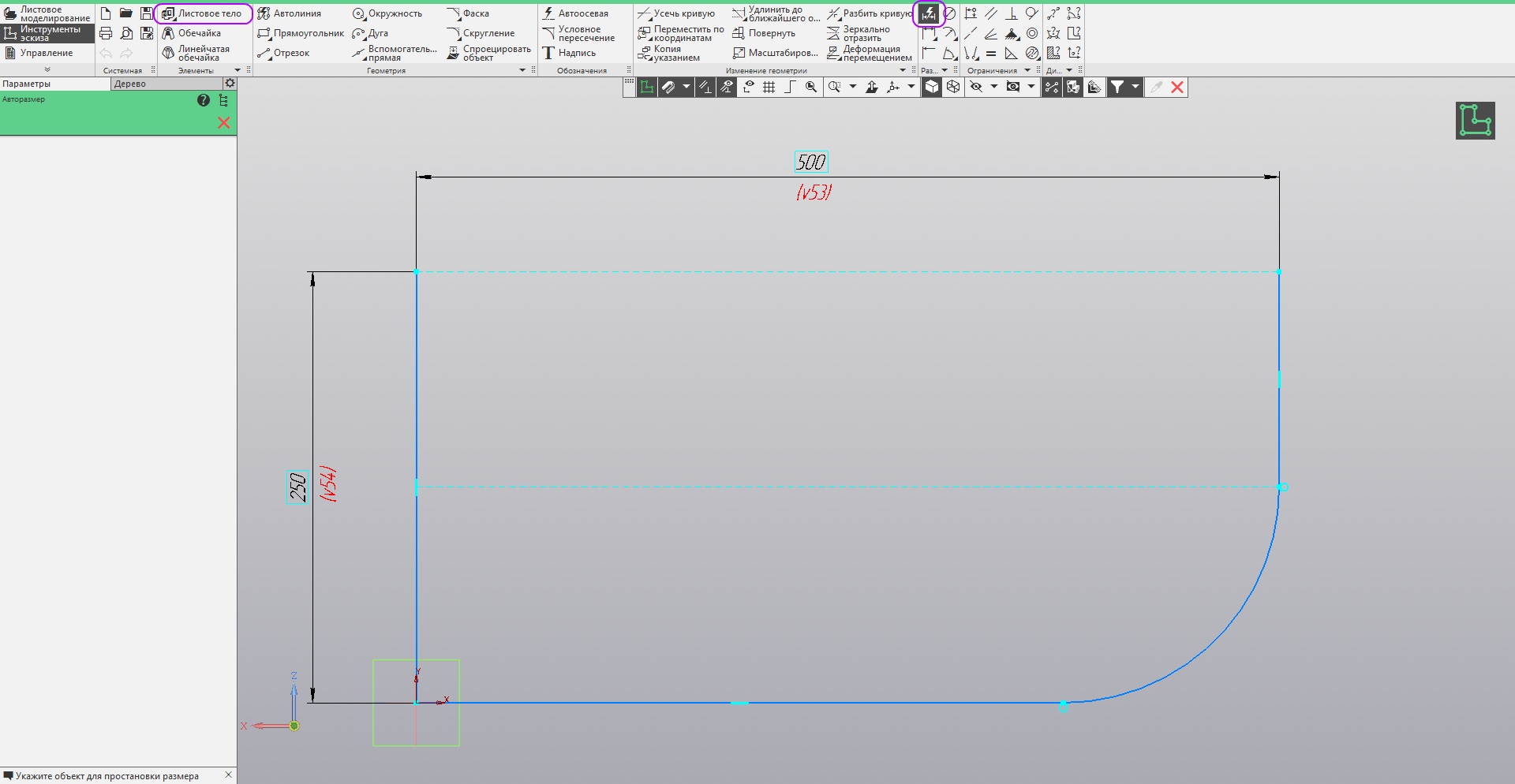
- Run the autoline line command. Create a sketch in the ZX plane. We build the first point just above the origin.
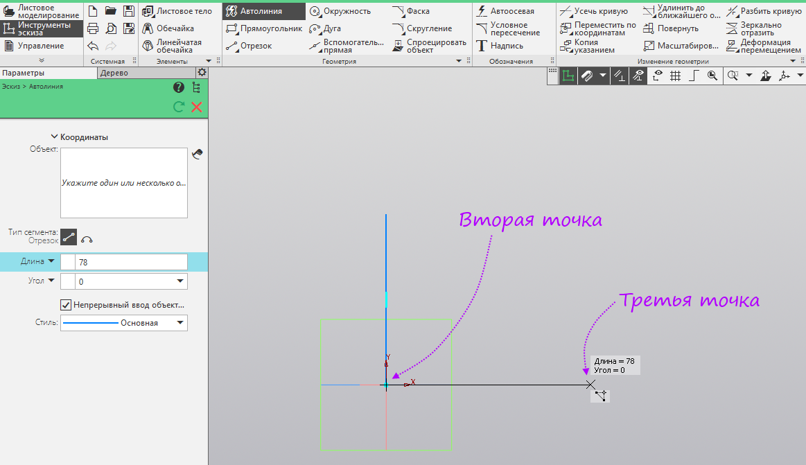
- We build the second point at the origin, and the third is slightly to the right of the origin.
- Switch to arc. We build an arbitrary arc to the level of the middle of the first segment.
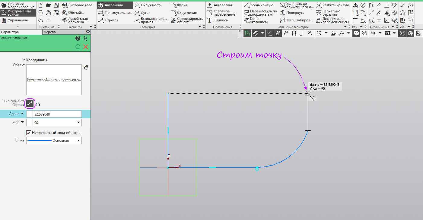
- Switch back to the segment. We build a vertical segment to the horizontal level of the beginning point of the construction.
- Launch the “Alignment” command. Align horizontally the start and end points of the autoline.
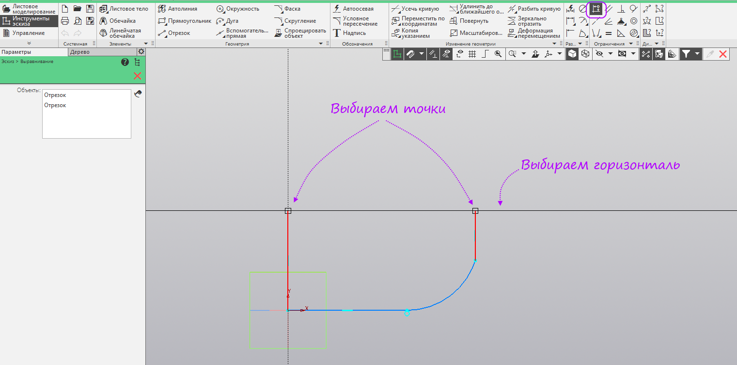
- Align horizontally the middle of the first segment and the second point of the arc.

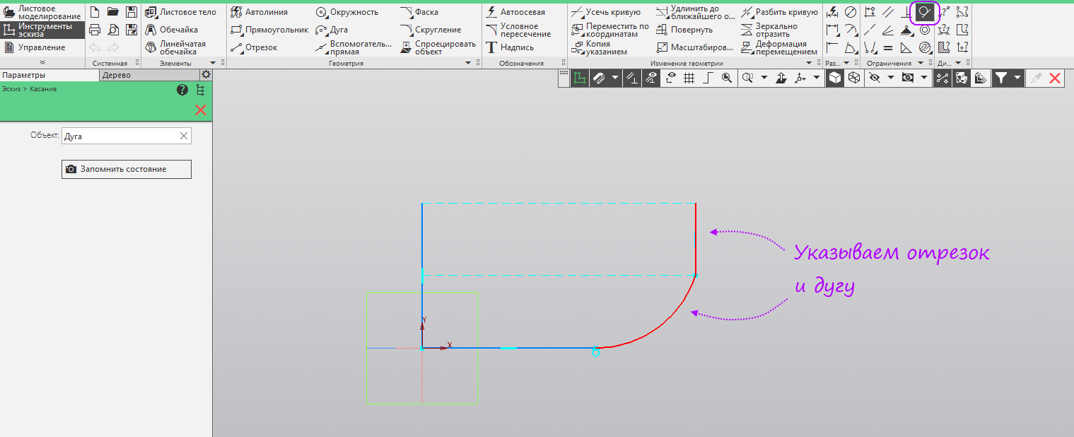
- Run the command "Touch" Specify the arc and the last segment.
- Run the command "Avtorazmer." We build the dimensions as in the picture. Run the command Sheet body.
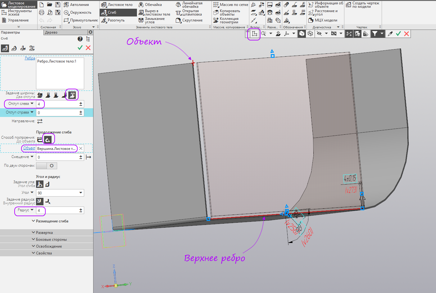
- We build a sheet body with a thickness of 2 mm, a radius of 4 mm, at a distance of 200 mm. Run the command "Fold".

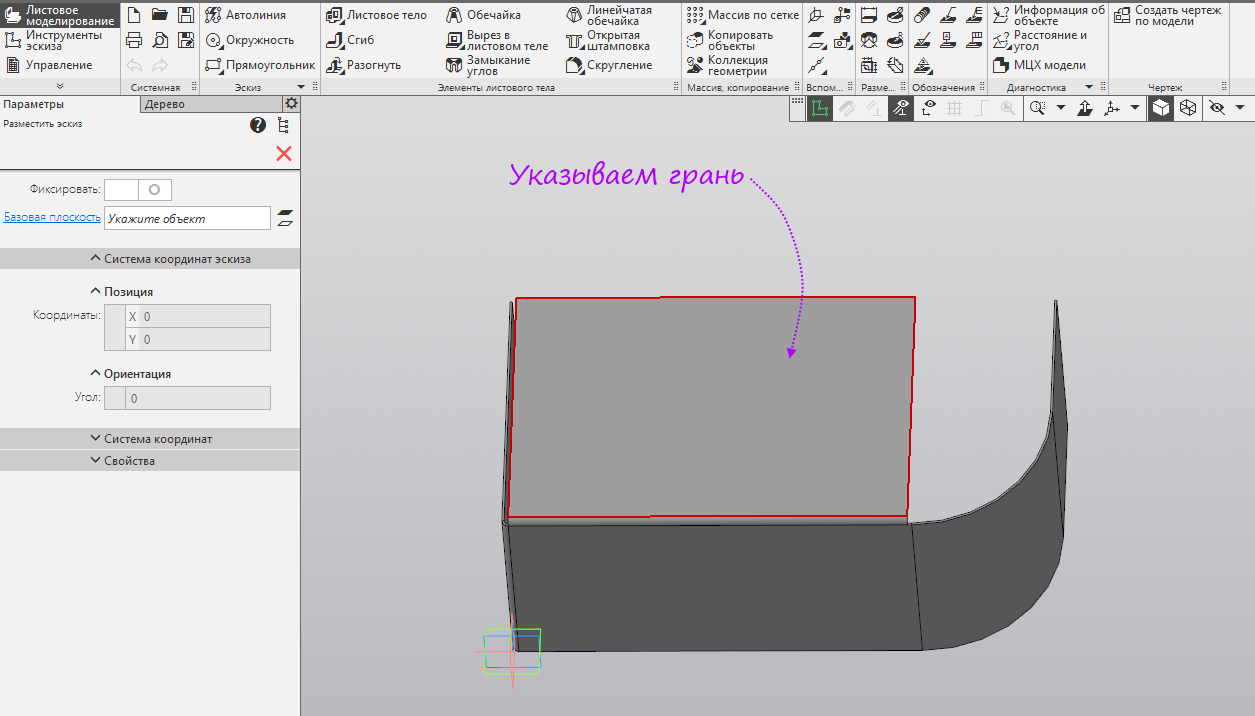
- Specify the top edge of the side face. Switch the width setting type to “Two indents”. Set the left margin to 4 mm. Establish a method for constructing the bend extension “To the object” We specify as an object one of the vertices of the vertical edge. Set the radius of 4 mm. Create a new sketch.
- Specify the bend face as the plane to build the sketch.
- Run the command "Project an object" and project the external vertical and arcuate bend edges.
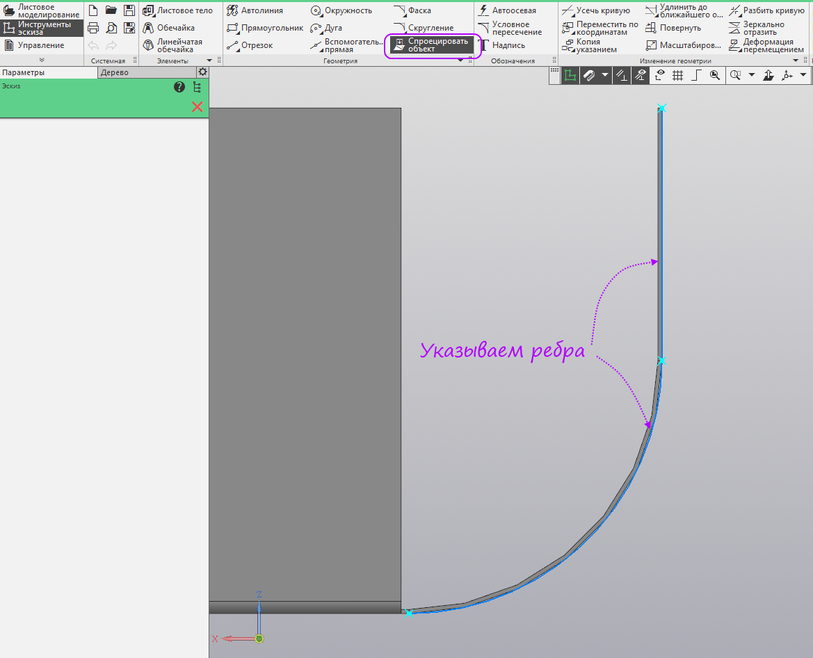
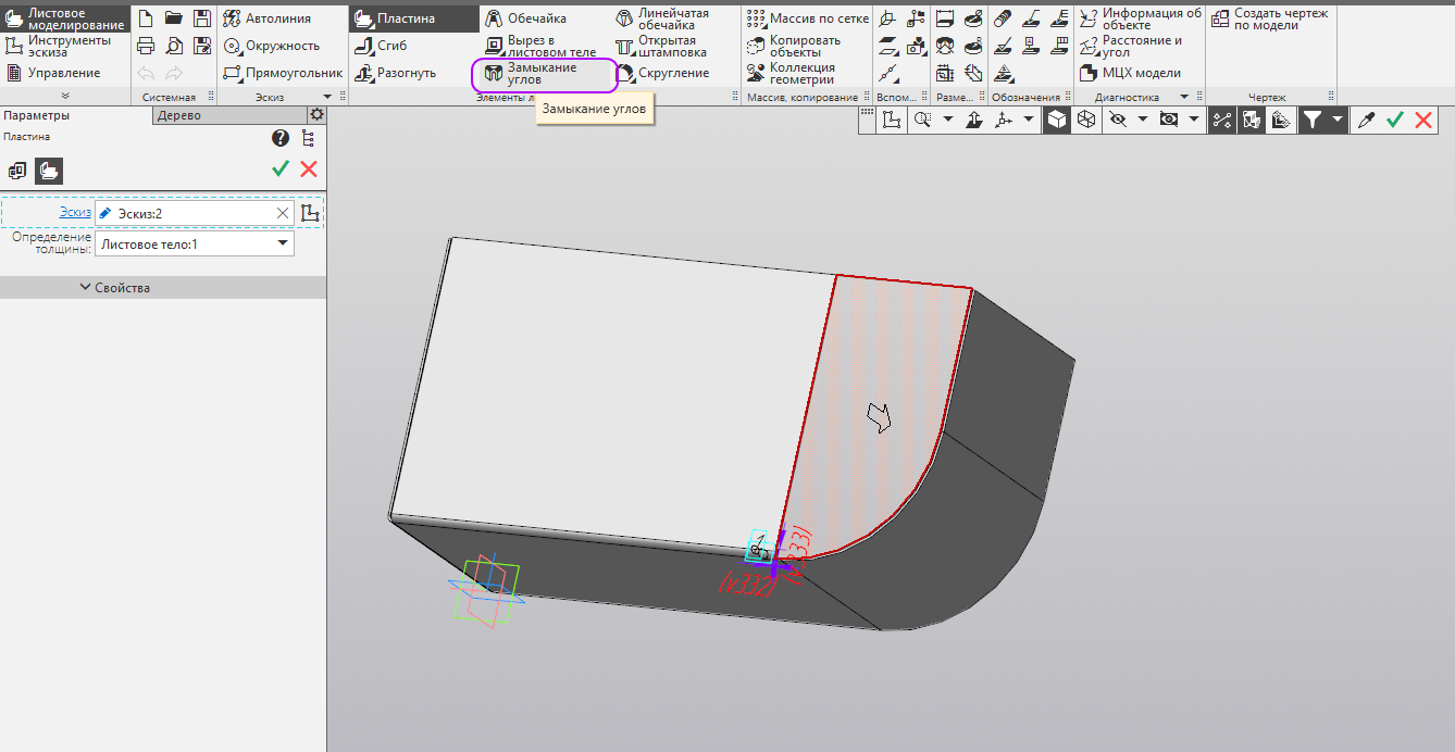
- We finish the sketch as in the picture. Run the command "Plate".
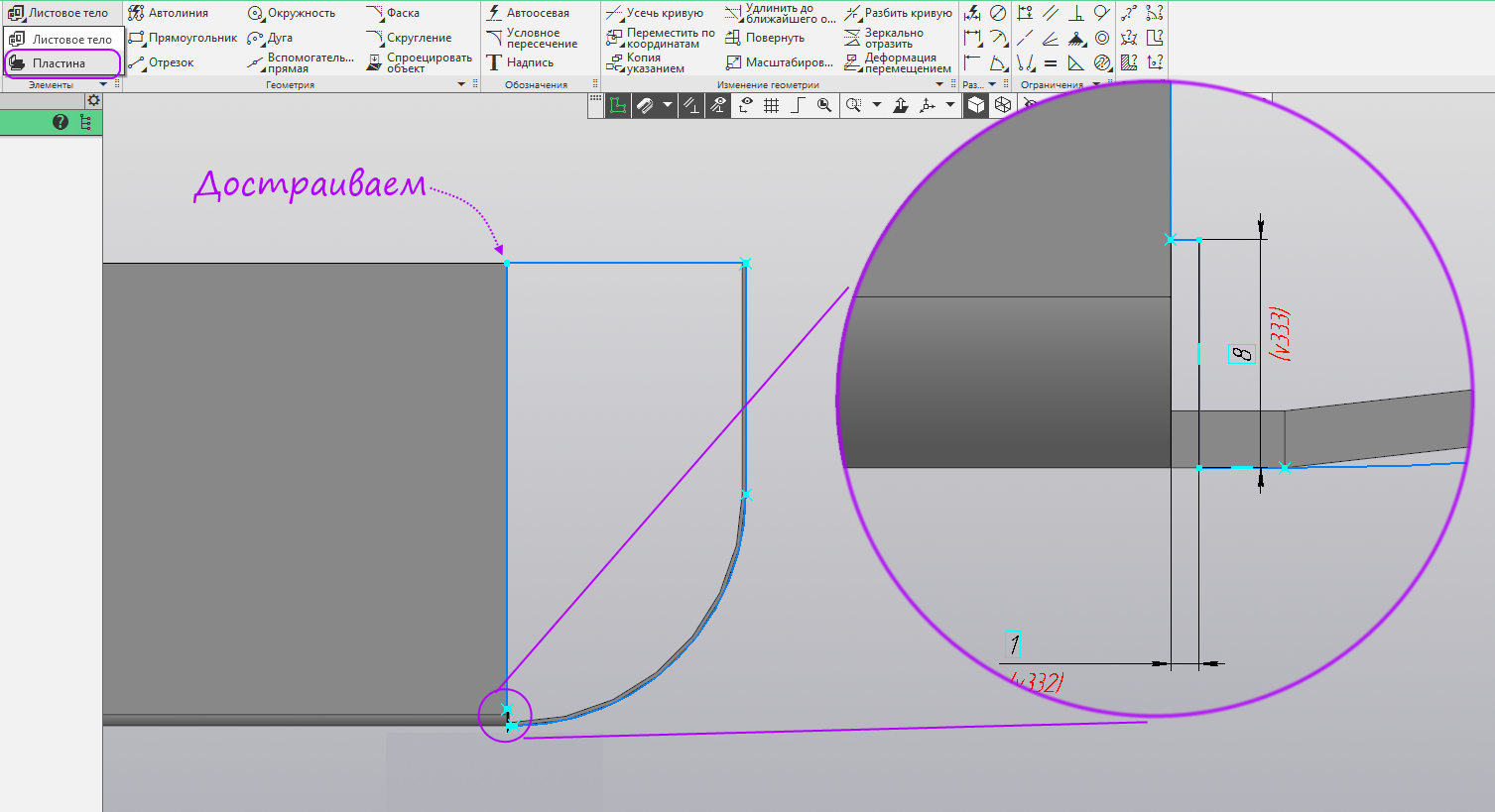
- In the settings you do not need to change anything. Run the command "Closing the corners."
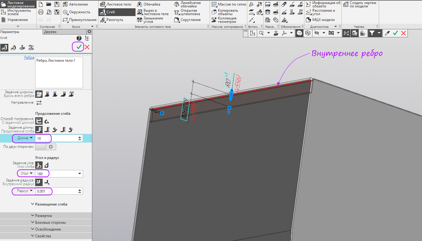
- Specify the fold. Set the closure method "Closing with overlapping." Run the command "Fold".

- Specify the inner edge of the vertical face of the curved part of the sheet part. Set an angle of 180 degrees, and a radius of 0.001 mm, a length of 10 mm. This bend is needed for stiffness, it also allows you to remove the sharp edge. We press the button "Create".
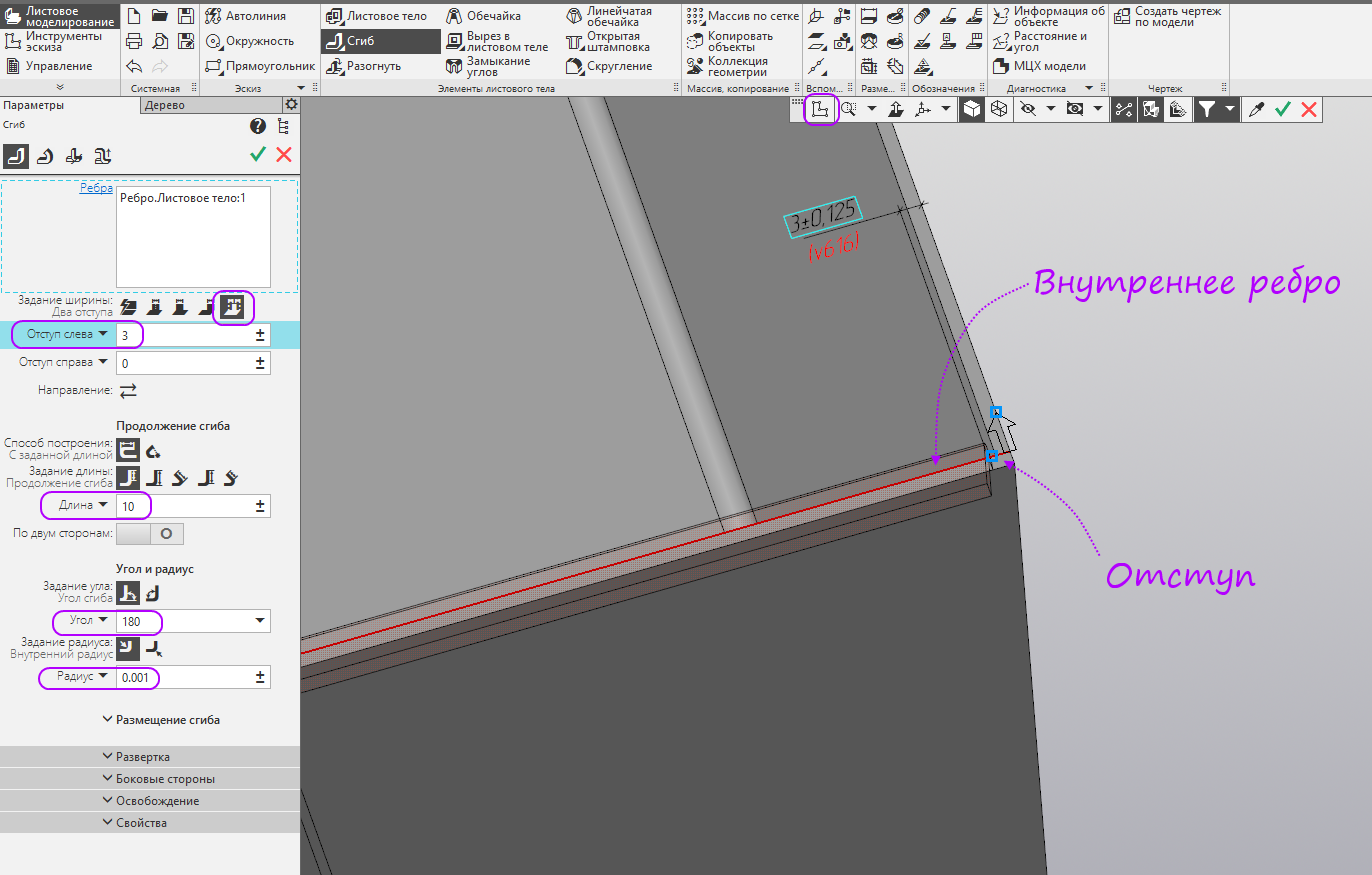
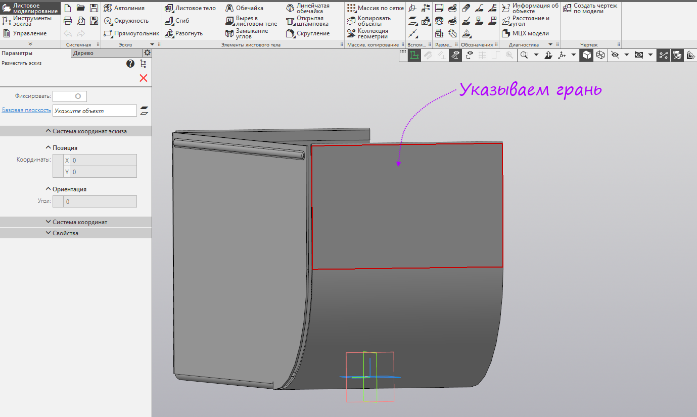
- Specify the inner edge of the opposite vertical edge. Switch the width setting type to “Two indents”. Set the left margin to 3 mm so that there is no intersection with the side fold. The remaining parameters do not change. Run the command "Sketch".
- Create a sketch on the side of the bend.
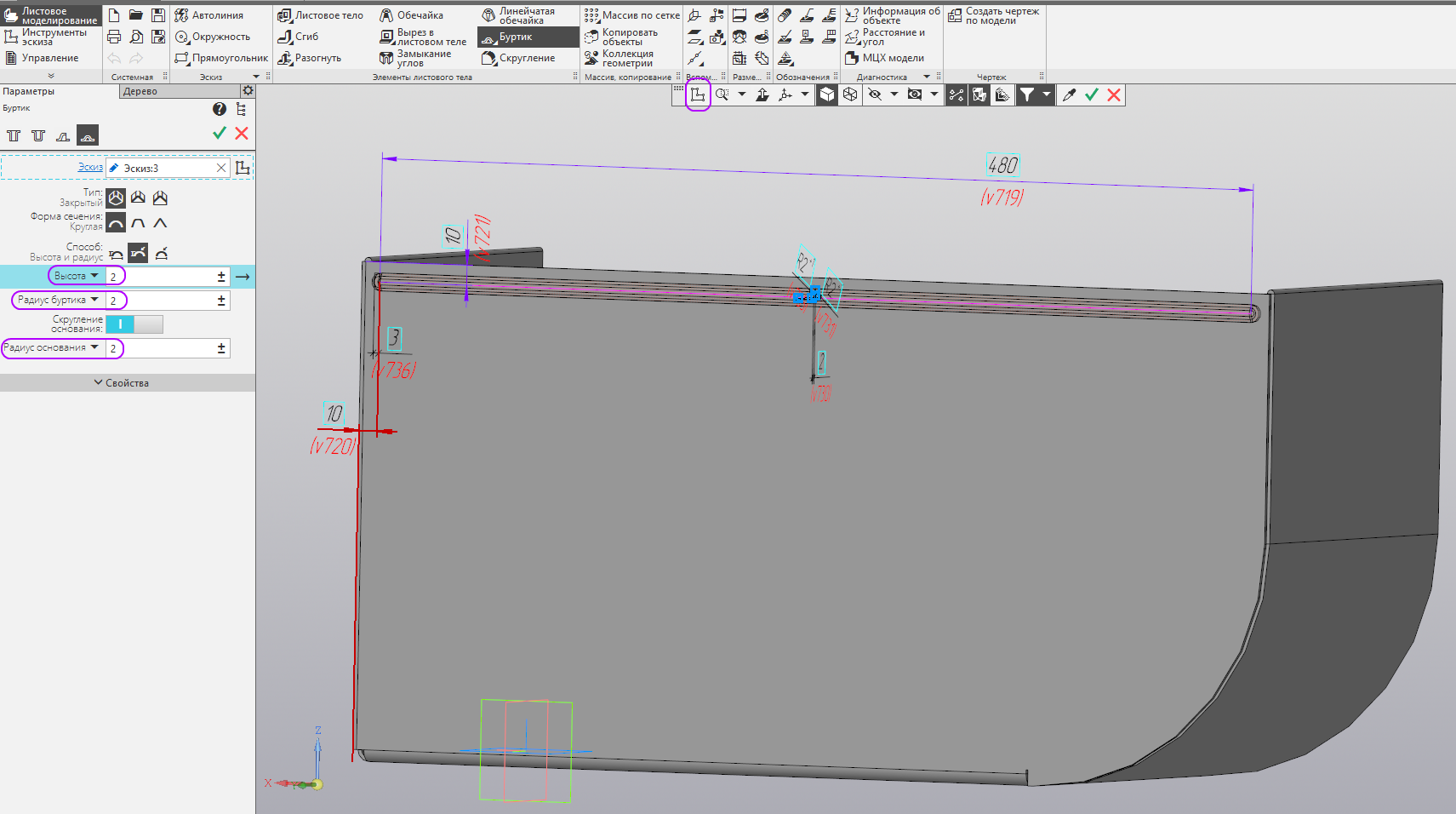
- We build a horizontal segment with dimensions as shown. Run the command "Burtik".

- Set the height of the collar 2 mm, radius - 2 mm and radius of the base of the collar - 2 mm. The resulting shoulder can be used to connect the case with the lid, it will also give bending stiffness. Run the command "Sketch".
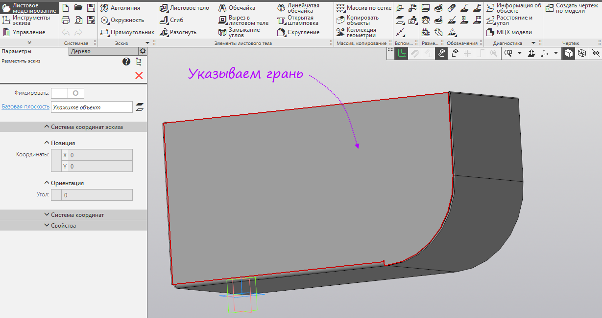
- Specify the vertical edge of the curved part.
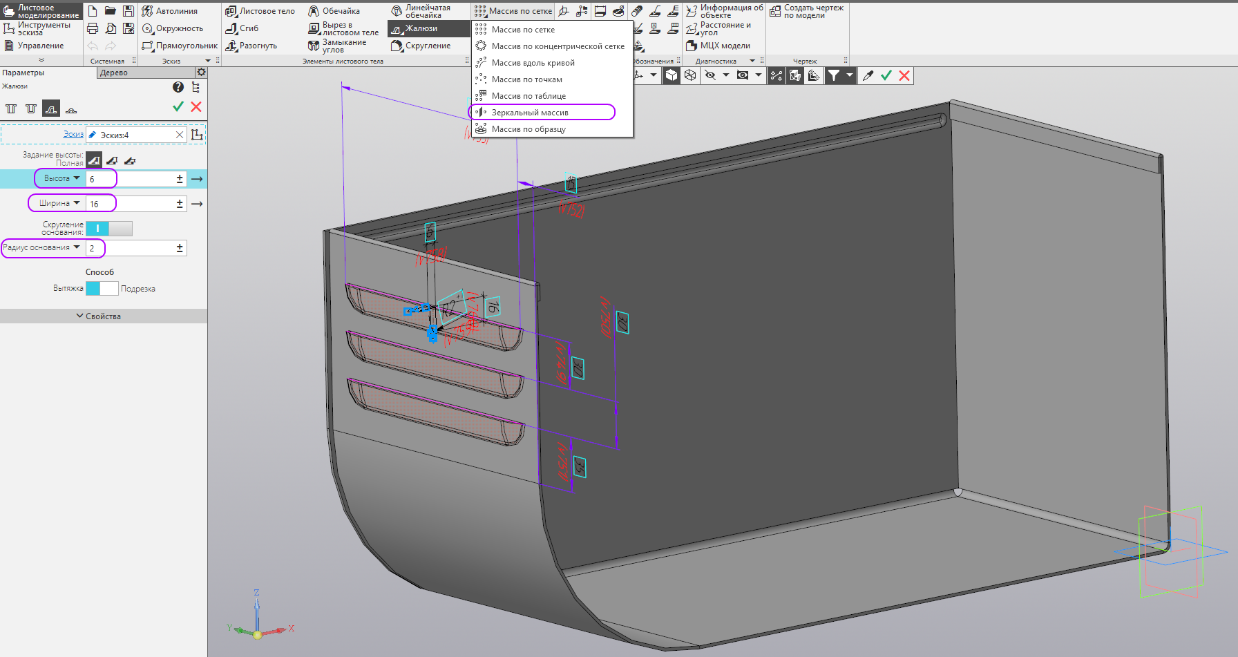
- We build three equal horizontal segments with dimensions as in the figure. Run the "Blinds" command.
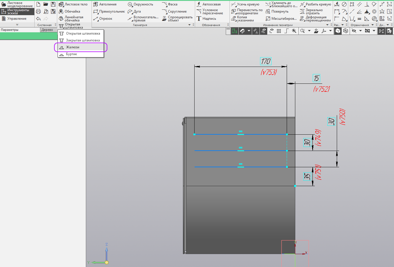
- Set the height of the blinds 6 mm, width - 16 mm and the radius of the base of the blinds - 2 mm. Blinds are needed if we need air flow into the housing. Run the "Mirror Array" command.
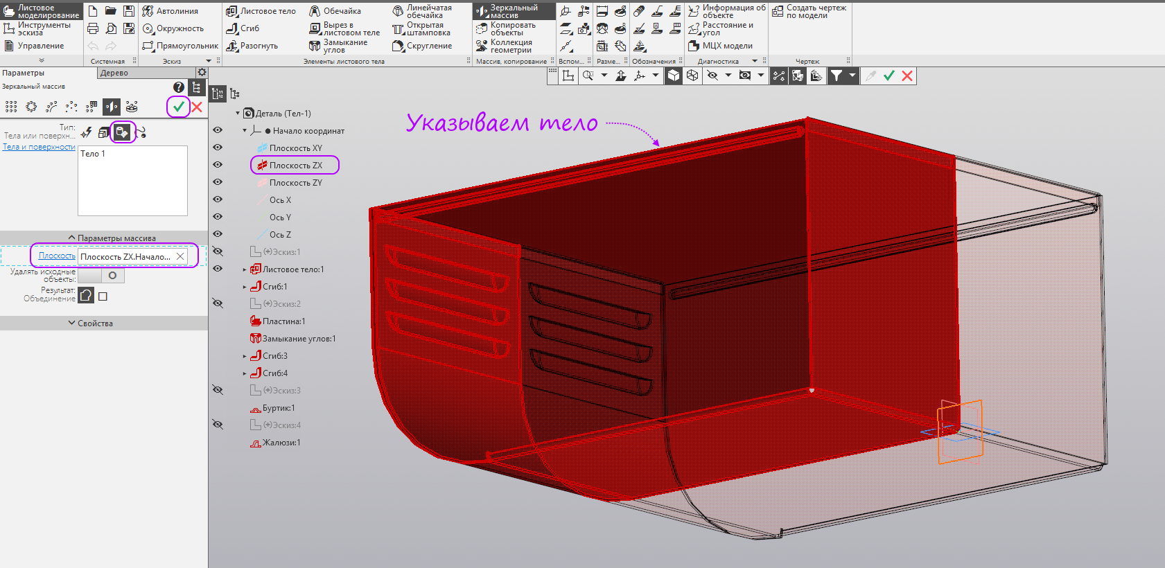
- The type of objects in the array is indicated - “Bodies or surfaces”, we specify the sheet body, and the Plane ZX is specified as the plane of symmetry. Create an operation, then exit the command (click the red cross), because we need to switch to the scanning mode.
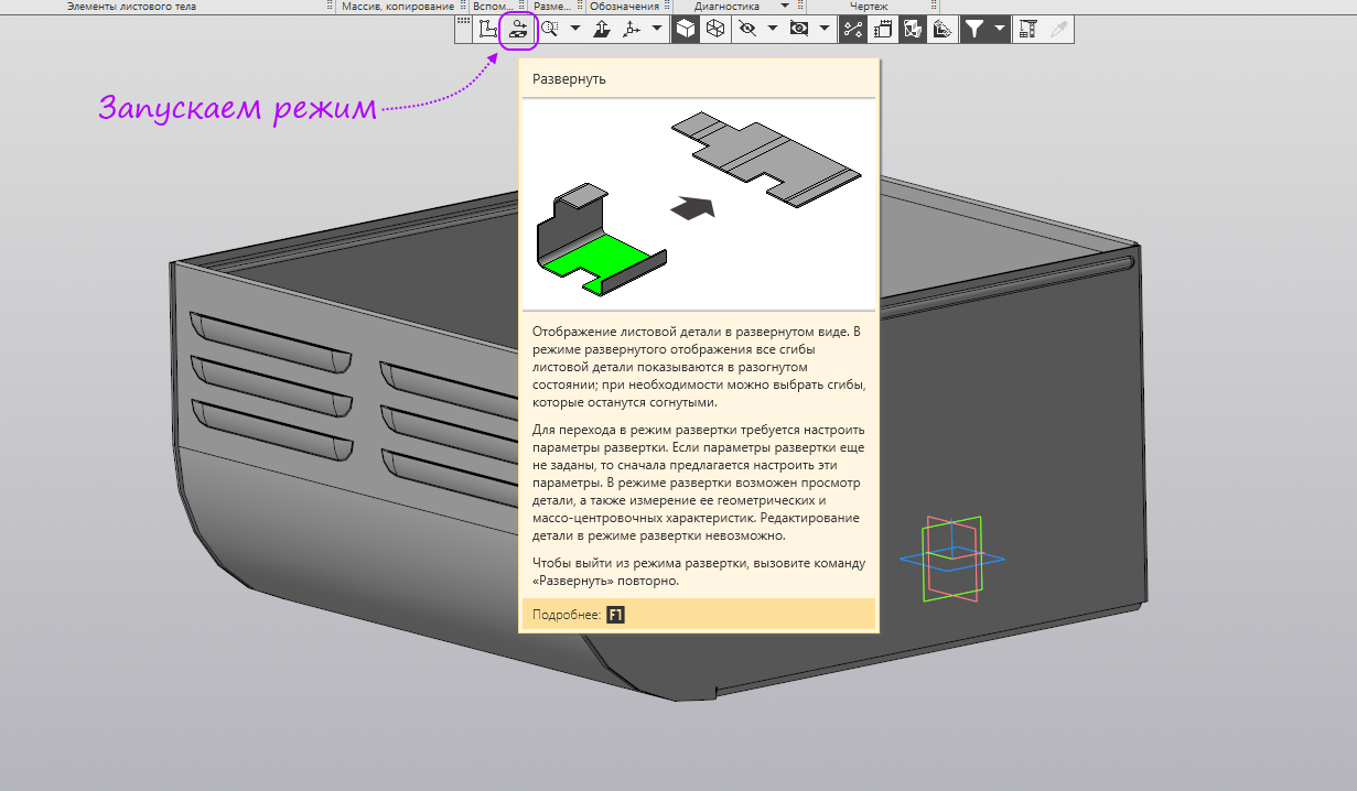
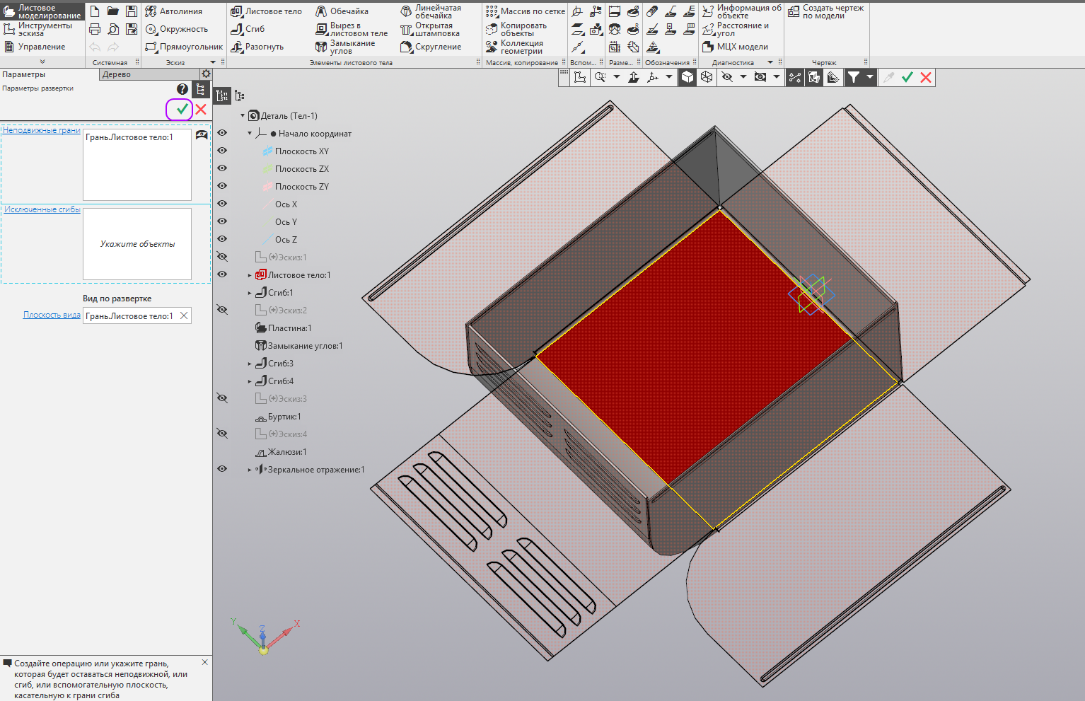
- Run the "Expand" mode.
- Specify the horizontal part of the sheet body.
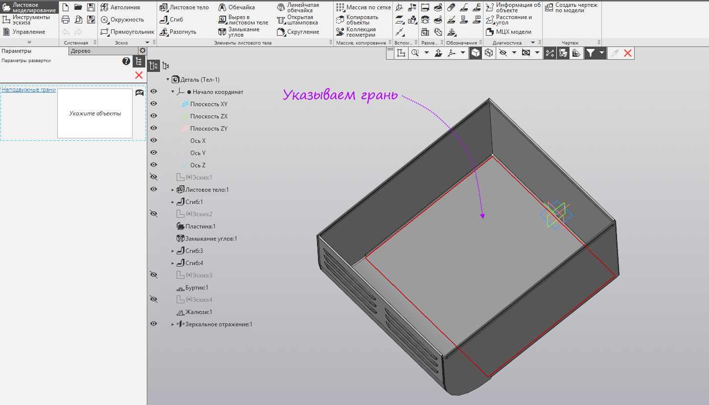
- A phantom of a sweep appeared. We press to create.
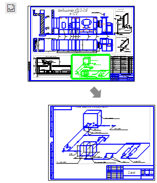
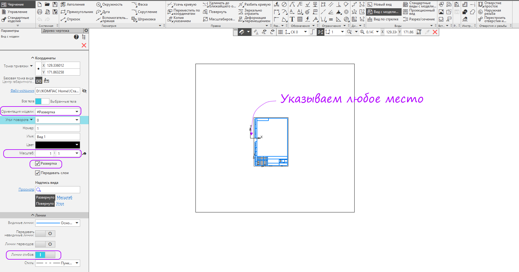
- Run the "Create a drawing by model" command.

- Select the orientation of the “Sweep” model, set the scale to 1: 1, activate the “Sweep” option, open the “Lines” section and turn on the display of fold lines. , .
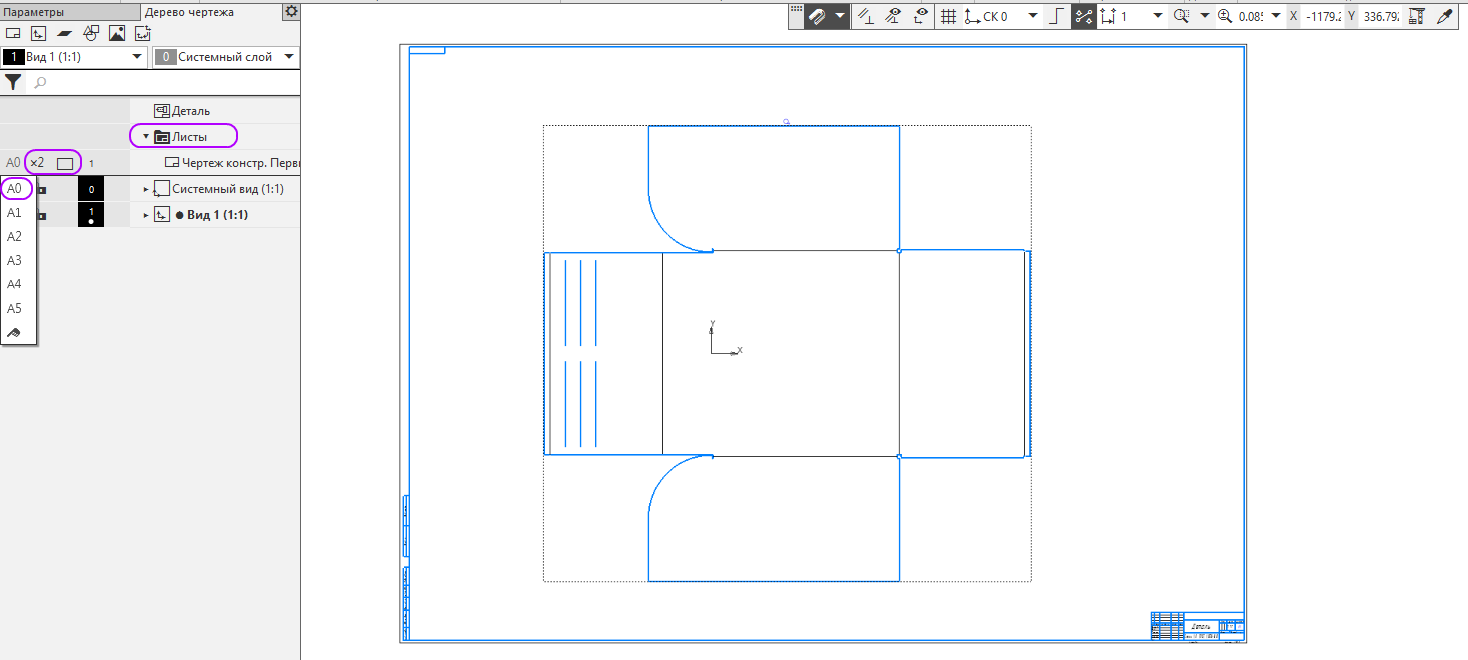
- «». 0, «2» . .
- DXF ( — … Dxf) . « ».
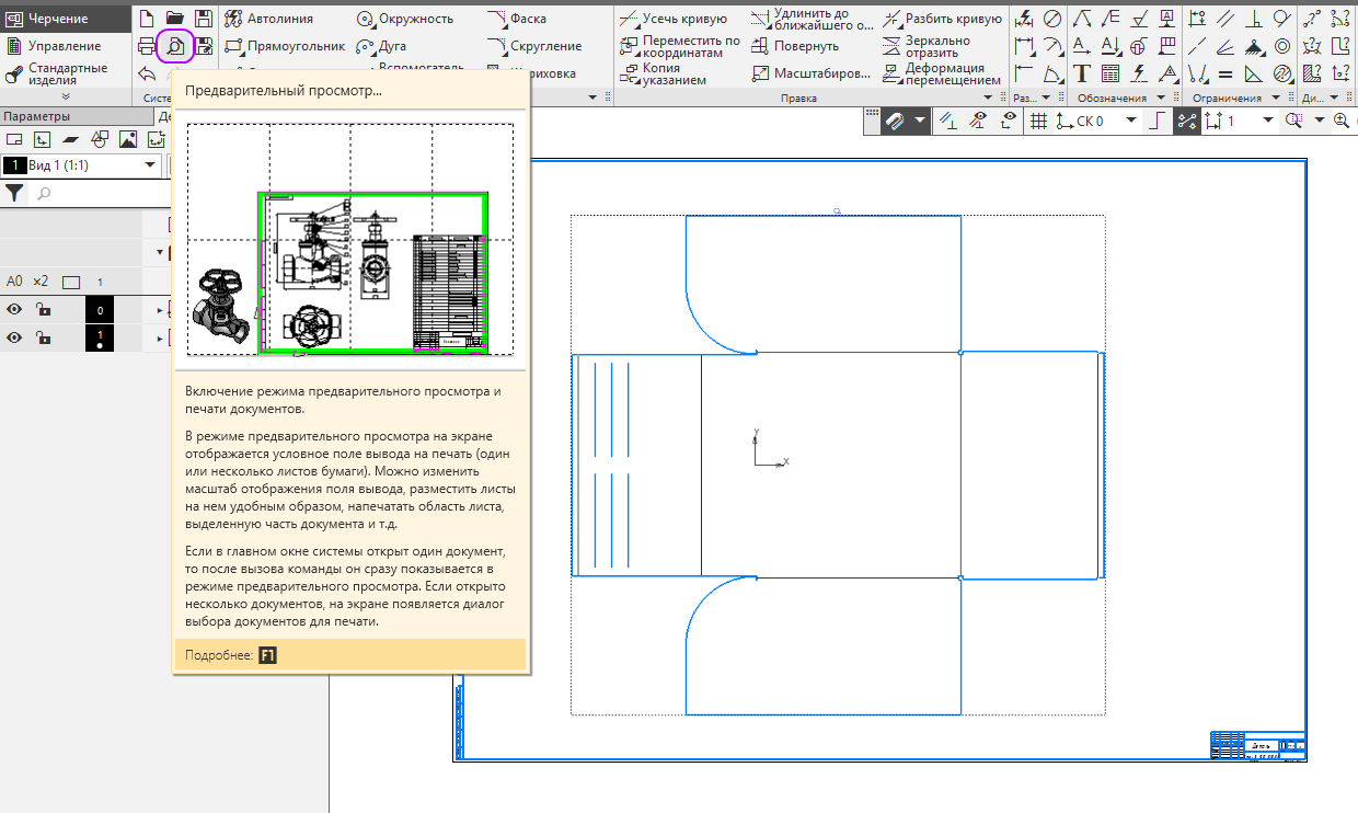
- .

- 1 (. . 100%). « ».
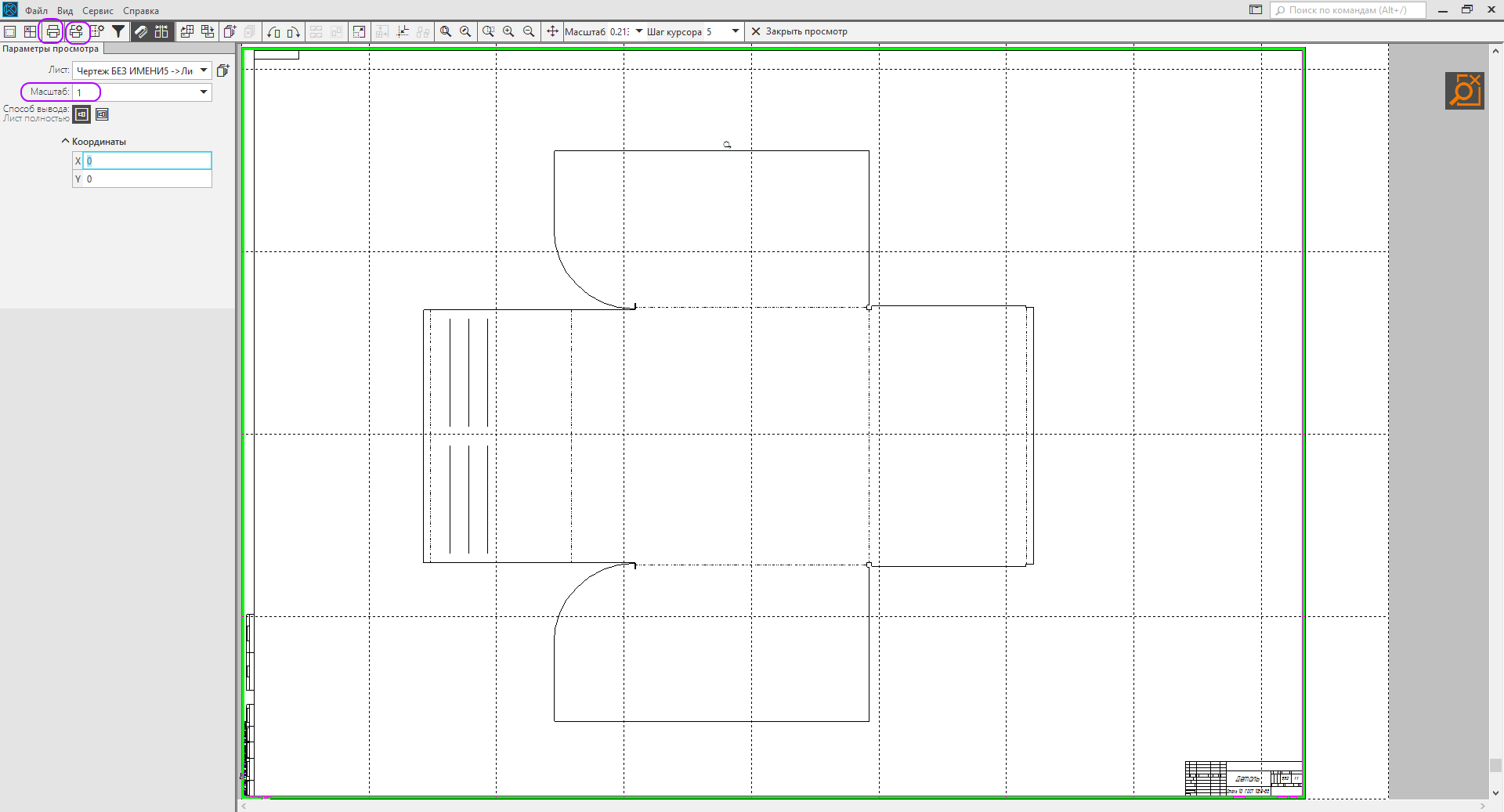
4 , , DXF .
Attention! — , .
, — , 1490 . 7 . , , 127 000 , . , .
— 550 , — 650 .
, , — , 1790 . . — 3D- -3D Home 3D-.

: (32 64 ), (, ), « 3D- 3D- -3D v17 Home» ( ), « », ( ) , , , .

« 3D- 3D- -3D v17 Home»
196 . 4 , . , 3D-. Stl .
7

10
— 550 , — 650 .
, , — , 1790 . . — 3D- -3D Home 3D-.
: (32 64 ), (, ), « 3D- 3D- -3D v17 Home» ( ), « », ( ) , , , .
« 3D- 3D- -3D v17 Home»
196 . 4 , . , 3D-. Stl .
Welcome! five
5
1. 12
12
. 14
. 26
. 35
3D-. 43
2. . 48
48
55
64
STL 68
3. .
72
72
76
79
89
4. 92
92
. 102
5. 109
109
116
122
6. 126
126
. 132
7. 137
137
142
8. 151
151
.
156
9. , 160
160
.
167
10. 169
169
. 189
. 192
5
1. 12
12
. 14
. 26
. 35
3D-. 43
2. . 48
48
55
64
STL 68
3. .
72
72
76
79
89
4. 92
92
. 102
5. 109
109
116
122
6. 126
126
. 132
7. 137
137
142
8. 151
151
.
156
9. , 160
160
.
167
10. 169
169
. 189
. 192
7
10
.
, -3D HomeSource: https://habr.com/ru/post/351490/
All Articles