Learn OpenGL. Lesson 4.9 - Geometric Shader

Geometric Shader
Between the stages of the execution of the vertex and fragment shader there is an optional stage intended for the execution of the geometric shader. At the input, the geometry shader has a set of vertices that form one of the primitives that are valid in OpenGL (points, triangles, ...). As a result of its work, the geometry shader can transform this set of vertices at its discretion, before passing it to the next shader stage. It is worth noting the most interesting feature of the geometry shader: during its operation, a set of input vertices can be converted to a completely different primitive representation, and can also generate completely new vertices based on the input data, increasing the total number of vertices.
Content
Part 1. Start
Part 2. Basic lighting
Part 3. Loading 3D Models
')
Part 4. OpenGL advanced features
- Opengl
- Creating a window
- Hello window
- Hello triangle
- Shaders
- Textures
- Transformations
- Coordinate systems
- Camera
Part 2. Basic lighting
Part 3. Loading 3D Models
')
Part 4. OpenGL advanced features
- Depth test
- Stencil test
- Mixing colors
- Face clipping
- Frame buffer
- Cubic cards
- Advanced data handling
- Advanced GLSL
Let's not harness for a long time and immediately turn to the example of a geometric shader:
#version 330 core layout (points) in; layout (line_strip, max_vertices = 2) out; void main() { gl_Position = gl_in[0].gl_Position + vec4(-0.1, 0.0, 0.0, 0.0); EmitVertex(); gl_Position = gl_in[0].gl_Position + vec4( 0.1, 0.0, 0.0, 0.0); EmitVertex(); EndPrimitive(); } At the beginning of the shader code, you must specify the type of primitive, the data of which comes from the vertex shader stage. This is done using the layout specifier, located before the in keyword. The primitive type specified in the specifier can take one of the following values, corresponding to the type of primitive processed by the vertex shader:
- points : When outputting GL_POINTS (1).
- lines : When outputting GL_LINES or GL_LINE_STRIP (2).
- lines_adjacency : When outputting GL_LINES_ADJACENCY or GL_LINE_STRIP_ADJACENCY (4).
- triangles : When outputting GL_TRIANGLES, GL_TRIANGLE_STRIP or GL_TRIANGLE_FAN (3).
- triangles_adjacency : When outputting GL_TRIANGLES_ADJACENCY or GL_TRIANGLE_STRIP_ADJACENCY (6).
As a result, almost all types of primitives are listed here that are valid for passing render functions like glDrawArrays () to the call. If rendered using GL_TRIANGLES , then in the specifier you should specify the parameter triangles . The number in brackets here means the minimum number of vertices that is contained in one primitive.
Further, you must also specify the type of output primitive for this shader. Accordingly, this is done through the layout specifier before the out keyword. In this example, a line_strip with a maximum of two vertices will be generated at the output.
If you forgot: the Line Strip primitive connects the points in the set, forming a continuous line between them, starting at two points in the set. Each additional point over two results in another drawn line segment stretching from a new point to the previous one. Below is an image of a five point segment:

The presented example of a shader can produce only individual straight segments, since we explicitly set the maximum number of vertices in the primitive to be two.
For the shader to be able to do something useful, it is necessary to obtain data from the output of the previous shader stage. GLSL provides the built-in variable gl_in , which can be represented approximately by the following structure:
in gl_Vertex { vec4 gl_Position; float gl_PointSize; float gl_ClipDistance[]; } gl_in[]; Thus, the variable is similar to the interface blocks discussed in the previous lesson , and contains several fields of which we are currently most interested in gl_Position , which contains the vertex position vector, which was set as a result of the vertex shader.
Note that this variable is an array, since most primitives contain more than one vertex, and the geometry shader stage receives all vertices of the primitive being processed as inputs.
Having received the vertex data from the vertex shader output, you can start generating new data, which is done using two special functions of the geometry shader: EmitVertex () and EndPrimitive () . It is expected that in the code you will generate at least one primitive declared as an output. In our example, you should issue at least one line_strip primitive.
void main() { gl_Position = gl_in[0].gl_Position + vec4(-0.1, 0.0, 0.0, 0.0); EmitVertex(); gl_Position = gl_in[0].gl_Position + vec4( 0.1, 0.0, 0.0, 0.0); EmitVertex(); EndPrimitive(); } Each call to EmitVertex () adds the current value in the variable gl_Position to the current instance of the primitive. When we call EndPrimitive () , all generated vertices are finally connected to the specified output primitive type. By repeating EndPrimitive () calls after one or more EmitVertex () calls, you can continue to create new instances of the primitives. Specifically, in the example, two vertices are generated, displaced a short distance from the position of the input vertex, and then the EndPrimitive () call is made , forming one line strip containing two vertices from these two generated vertices.
So, knowing (in theory) how the geometry shader works, you probably already guessed what the effect of this example is. At the input, the shader accepts point primitives and creates horizontal lines based on them, where the input vertex lies exactly in the middle. The output of the program using such a shader is presented below:

Not too impressive, but already interesting, given the fact that we got such results by executing just one draw call:
glDrawArrays(GL_POINTS, 0, 4); Although this example is quite simple, it demonstrates an important principle: the ability to dynamically create new shapes using geometric shaders. Later we will look at some more interesting effects implemented on the basis of geometry shaders, but in the meantime let's work on the basics using simple shaders.
Using a geometric shader
To demonstrate the use of the geometry shader, we use a simple program that renders four points lying on the XoY plane in normalized device coordinates (NDC). Coordinates of points:
float points[] = { -0.5f, 0.5f, // - 0.5f, 0.5f, // - 0.5f, -0.5f, // - -0.5f, -0.5f // - }; The vertex shader is simple - you just need to map the points to the desired plane:
#version 330 core layout (location = 0) in vec2 aPos; void main() { gl_Position = vec4(aPos.x, aPos.y, 0.0, 1.0); } The fragment shader is also trivial and simply uses a hard-coded color for the fragments:
#version 330 core out vec4 FragColor; void main() { FragColor = vec4(0.0, 1.0, 0.0, 1.0); } In the program code, we, as usual, create VAO and VBO for vertex data and render the render call with glDrawArrays () :
shader.use(); glBindVertexArray(VAO); glDrawArrays(GL_POINTS, 0, 4); As a result, on the screen is total darkness and four barely noticeable green dots:

It is somehow sad if we have learned so much just to bring out such a depressing picture. Therefore, we will urgently intervene in the scene and dilute this darkness using the capabilities of the geometric shader.
But first, for training purposes, you have to create and figure out how the end-to-end geometry shader works, which simply takes the data of the input primitive and sends it to the output unchanged:
#version 330 core layout (points) in; layout (points, max_vertices = 1) out; void main() { gl_Position = gl_in[0].gl_Position; EmitVertex(); EndPrimitive(); } At the moment, you can already understand the shader code without prompts. Here we simply generate the vertex in the position obtained from the vertex shader, and then generate all the same point primitive.
A geometric shader requires compilation and linking to a program object exactly the same as the vertex and fragment shaders. However, this time the shader object is created with GL_GEOMETRY_SHADER as the shader type:
geometryShader = glCreateShader(GL_GEOMETRY_SHADER); glShaderSource(geometryShader, 1, &gShaderCode, NULL); glCompileShader(geometryShader); ... glAttachShader(program, geometryShader); glLinkProgram(program); In fact, the compilation code is exactly the same as for other types of shaders. Do not forget about checking for compilation and linking errors!
When performing should get a familiar picture:
Got the same thing as without a geometric shader ... Boring! But, since the points are still displayed, we at least made sure that our shader is working and you can move on to something more interesting.
We build houses
Drawing simple lines and points is not exactly what we expected, so we will try to add some creativity and draw houses at the points specified by the input vertices. To do this, we need to change the type of the output primitive to triangle_strip and draw three triangles: two to create a square base and one for the roof.
Primitive Triangle Strip in OpenGL is a more efficient method of drawing triangles requiring fewer vertices at the entrance. After rendering the first triangle, each subsequent vertex creates another triangle adjacent to the previous one. If six vertices are specified in the triangle strip , then the result will be the following sequence of triangles: (1,2,3), (2,3,4), (3,4,5) and (4,5,6), that will result in four drawn triangles. This primitive requires specifying at least three vertices for a successful rendering. In general, N-2 triangles will be output; with six vertices, we got 6-2 = 4 triangles, which is illustrated below:
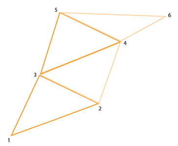
Using the triangle strip, you can easily create the desired shape of the house of all three adjacent triangles by specifying them in the correct order. The following image shows the order in which you want to display the vertices in order to get the desired type of triangles. The blue dot shows the position of the input vertex:

Resulting Geometric Shader:
#version 330 core layout (points) in; layout (triangle_strip, max_vertices = 5) out; void build_house(vec4 position) { gl_Position = position + vec4(-0.2, -0.2, 0.0, 0.0); // 1:bottom-left EmitVertex(); gl_Position = position + vec4( 0.2, -0.2, 0.0, 0.0); // 2:bottom-right EmitVertex(); gl_Position = position + vec4(-0.2, 0.2, 0.0, 0.0); // 3:top-left EmitVertex(); gl_Position = position + vec4( 0.2, 0.2, 0.0, 0.0); // 4:top-right EmitVertex(); gl_Position = position + vec4( 0.0, 0.4, 0.0, 0.0); // 5:top EmitVertex(); EndPrimitive(); } void main() { build_house(gl_in[0].gl_Position); } The shader creates five vertices in positions that are offset from the position of the input vertex, putting them all in a single triangle strip primitive. This primitive is then sent to rasterization, and a fragmentary shader paints its surface in green. We get one green house for each entry point:

Here you can see that each house is really made up of three triangles - and all this is built on the basis of a single point of input data.
But something still looks boring! Let's try to paint each of the houses in their own color. To do this, we will organize another vertex attribute storing vertex color information. The vertex shader reads the attribute value for the vertex and passes it to the geometric shader, which in turn sends the color value to the fragment shader.
The updated vertex data is as follows:
float points[] = { -0.5f, 0.5f, 1.0f, 0.0f, 0.0f, // - 0.5f, 0.5f, 0.0f, 1.0f, 0.0f, // - 0.5f, -0.5f, 0.0f, 0.0f, 1.0f, // - -0.5f, -0.5f, 1.0f, 1.0f, 0.0f // - }; Next, we specify the vertex shader code for transmitting the color attribute to the geometric shader using the interface unit:
#version 330 core layout (location = 0) in vec2 aPos; layout (location = 1) in vec3 aColor; out VS_OUT { vec3 color; } vs_out; void main() { gl_Position = vec4(aPos.x, aPos.y, 0.0, 1.0); vs_out.color = aColor; } Obviously, we will need to define an interface unit of the same type (but with a different name) in a geometric shader:
in VS_OUT { vec3 color; } gs_in[]; Since the geometry shader is executed on entire sets of input vertices, its input parameter is always an array, even in cases when a single vertex is supplied to the input.
In fact, we do not need to use interface blocks to transfer data to the geometry shader. If the vertex shader transmitted a vector with color as out vec3 vColor , then it would be possible to write like this:in vec3 vColor[];
However, in general, working with interface blocks is much easier, especially in geometry shaders. In practice, the input parameters of geometry shaders are often represented by fairly large data sets and combining them into a single interface unit, represented by an array, is quite an expected step.
You should also declare the output variable that sends the color data to the fragment shader:
out vec3 fColor; Since the fragment shader expects one (interpolated) color value, there is no point in sending arrays of color vectors. That is why fColor here is not an array, but a single vector. When we generate a vertex, each of them will remember the last value that was in the variable fColor for its call to the fragment shader. Accordingly, for our houses we can fill fColor only once with the color obtained from the vertex shader stage to set the color of the whole house:
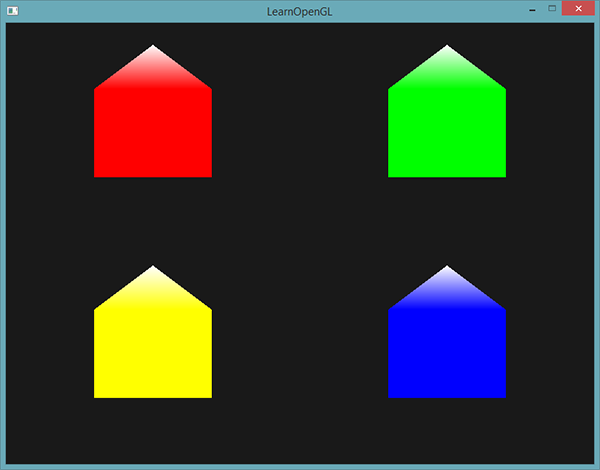
fColor = gs_in[0].color; // gs_in[0] gl_Position = position + vec4(-0.2, -0.2, 0.0, 0.0); // 1:- EmitVertex(); gl_Position = position + vec4( 0.2, -0.2, 0.0, 0.0); // 2:- EmitVertex(); gl_Position = position + vec4(-0.2, 0.2, 0.0, 0.0); // 3:- EmitVertex(); gl_Position = position + vec4( 0.2, 0.2, 0.0, 0.0); // 4:- EmitVertex(); gl_Position = position + vec4( 0.0, 0.4, 0.0, 0.0); // 5: EmitVertex(); EndPrimitive(); As a result, all generated vertices will store the color value from the fColor variable, which corresponds to the colors from the vertex attributes. Now each house is painted in its own color:

Add a little more creativity and arrange a virtual winter by sprinkling snow on the roofs of the houses. For this last vertex, we separately assign white color:
fColor = gs_in[0].color; gl_Position = position + vec4(-0.2, -0.2, 0.0, 0.0); // 1:- EmitVertex(); gl_Position = position + vec4( 0.2, -0.2, 0.0, 0.0); // 2:- EmitVertex(); gl_Position = position + vec4(-0.2, 0.2, 0.0, 0.0); // 3:- EmitVertex(); gl_Position = position + vec4( 0.2, 0.2, 0.0, 0.0); // 4:- EmitVertex(); gl_Position = position + vec4( 0.0, 0.4, 0.0, 0.0); // 5: fColor = vec3(1.0, 1.0, 1.0); EmitVertex(); EndPrimitive(); As a result, we have:
You can compare your application code with an example .
I think at this point it is already clear to you that geometric shaders give ample creative possibilities, even using simple primitives. Since the geometry is created dynamically inside the super-high speed GPU core, this turns out to be much more efficient than specifying similar geometry using vertex buffers. Geometric shaders offer ample opportunities to optimize the rendering of simple and frequently repeated cubic-type figures for voxel renders or grass stalks in open space scenes.
Exploding objects
Drawing houses is, of course, great, but not something we often have to work with. Therefore, let us add heat and proceed directly to blasting three-dimensional models! Hmm, you probably won't have to do this too often, but it will be an excellent demonstration of the capabilities of geometric shaders.
By object blasting, we mean not the literal destruction of our precious peaks, but the movement of each triangle along the normal direction over time. As a result, this effect gives the semblance of an explosion of an object, dividing it into separate triangles moving in the direction of its normal vector. Below is the effect applied to the nanosuit model:

What is great is that using a geometric shader allows the effect to work on any object, regardless of its complexity.
Since we need to move the triangles along the normal vector, we have to start counting it. Specifically, we need to find a vector perpendicular to the surface of the triangle, having only three of its vertices. From the transformational lesson you probably remember that a vector perpendicular to the other two can be obtained using the vector product multiplication ( cross product ). If we could find two vectors a and b parallel to the surface of the triangle, then the vector perpendicular to the surface would simply be the result of their vector product. Actually, the geometry shader code below does just that: it calculates the normal vector using three vertices of the input triangle:
vec3 GetNormal() { vec3 a = vec3(gl_in[0].gl_Position) - vec3(gl_in[1].gl_Position); vec3 b = vec3(gl_in[2].gl_Position) - vec3(gl_in[1].gl_Position); return normalize(cross(a, b)); } Here, using subtraction, we obtain two vectors a and b parallel to the surface of the triangle. Subtracting vectors gives another vector representing the difference of the two original ones. Since all three vertices lie in the plane of the triangle, the difference between any vectors representing the vertices of the triangle generates vectors parallel to the surface of the triangle. Pay attention to the order of the parameters in taking out the cross () function: if we swapped a and b , then the direction of the normal vector would be opposite.
Now that you have a way to find the normal, you can go to the implementation of the explode () function. The function accepts the normal vector and the vertex position vector, and returns the new vertex position shifted along the normal:
vec4 explode(vec4 position, vec3 normal) { float magnitude = 2.0; vec3 direction = normal * ((sin(time) + 1.0) / 2.0) * magnitude; return position + vec4(direction, 0.0); } The code is pretty obvious. The sin () function depends on the time variable associated with the current time, and periodically returns values in the interval [-1., 1.]. Since the explosion effect inside (implosion) is of no interest to us, we limit the sin () values to the interval [0., 1.]. The resulting value and the magnitude control constant are then used to scale the normal vector in the calculation of the final direction vector. This vector is added to the input parameter of the vertex position to get a new, shifted position.
The full code of the geometric shader of the explosion effect when using the render code of the 3D model files from the corresponding lesson is given below:
#version 330 core layout (triangles) in; layout (triangle_strip, max_vertices = 3) out; in VS_OUT { vec2 texCoords; } gs_in[]; out vec2 TexCoords; uniform float time; vec4 explode(vec4 position, vec3 normal) { ... } vec3 GetNormal() { ... } void main() { vec3 normal = GetNormal(); gl_Position = explode(gl_in[0].gl_Position, normal); TexCoords = gs_in[0].texCoords; EmitVertex(); gl_Position = explode(gl_in[1].gl_Position, normal); TexCoords = gs_in[1].texCoords; EmitVertex(); gl_Position = explode(gl_in[2].gl_Position, normal); TexCoords = gs_in[2].texCoords; EmitVertex(); EndPrimitive(); } Notice that before each vertex is spawned, we pass in the corresponding texture coordinates.
Also, do not forget to set the value for the uniforms time in your client code:
shader.setFloat("time", glfwGetTime()); The result is a scene with a model that periodically explodes and returns to its original state. The example is frivolous, but it leads well to the in-depth use of geometric shaders.
The resulting code can be compared with an example .
Display normal vectors
This time we will try to implement something really useful in practice using the geometry shader: the mapping of normal vectors of the rendered geometry. When implementing lighting algorithms, you will inevitably encounter strange results and visual glitches, the cause of which will be difficult to determine. One of the most common errors when working with lighting is setting incorrect normals, as if due to errors with loading vertex data, errors specifying the format of vertex attributes, or simply conversion errors directly in the shaders. It would be great to have a tool to determine the correctness of the provided normals.Normal rendering is one such tool, and geometric shaders are simply created to implement it.
The idea is simple: first, we render the scene in the usual way without the geometry shader turned on, then we do the second pass, but displaying only the normals generated by the geometry shader. The shader will accept a triangle-type primitive at the input and create three segments in the direction of the normal vector at the position of each vertex. In the form of pseudocode it looks something like this:
shader.use(); DrawScene(); normalDisplayShader.use(); DrawScene(); This time, the geometry shader will use the normals, supplied as a vertex attribute, instead of on the fly. The geometric shader receives at the input of the position vector in the clip space ( clip space ), so we should convert the normal vector into the same space. But before we do this, we will need to transform the normal vectors using a normal matrix - so we take into account the scaling and rotation (given the species and model matrices). All this is done in the vertex shader:
#version 330 core layout (location = 0) in vec3 aPos; layout (location = 1) in vec3 aNormal; out VS_OUT { vec3 normal; } vs_out; uniform mat4 projection; uniform mat4 view; uniform mat4 model; void main() { gl_Position = projection * view * model * vec4(aPos, 1.0); mat3 normalMatrix = mat3(transpose(inverse(view * model))); vs_out.normal = normalize(vec3(projection * vec4(normalMatrix * aNormal, 0.0))); } The normal vector converted into the clip space is transmitted to the next shader stage via the interface unit. The geometry shader reads the vertex attributes (position vector and normal) and outputs a segment in the direction of the normal at the position of each vertex:
#version 330 core layout (triangles) in; layout (line_strip, max_vertices = 6) out; in VS_OUT { vec3 normal; } gs_in[]; const float MAGNITUDE = 0.4; void GenerateLine(int index) { gl_Position = gl_in[index].gl_Position; EmitVertex(); gl_Position = gl_in[index].gl_Position + vec4(gs_in[index].normal, 0.0) * MAGNITUDE; EmitVertex(); EndPrimitive(); } void main() { GenerateLine(0); // GenerateLine(1); // ... GenerateLine(2); // ... } I think at the moment the code does not require additional explanations. I will only note that the normal vector is scaled using the MAGNITUDE constant , which allows you to limit the length of the displayed segment (otherwise it would be a bit too large).
Since the output of the normals serves primarily a debugging target, they can be output simply by lines of the same color, using the fragment shader:
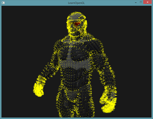
#version 330 core out vec4 FragColor; void main() { FragColor = vec4(1.0, 1.0, 0.0, 1.0); } As a result, the combination of rendering the model using a regular shader and re-rendering using a fresh normal rendering shader will give the following picture:
, , . , , - , .
.
PS : We have a telegram-konf to coordinate transfers. If there is a serious desire to help with the translation, then you are welcome!
Source: https://habr.com/ru/post/350782/
All Articles