[Not only to students] Packet Tracer Lab
Laboratory job
The company rented 3 premises in the business center. In these rooms there are only bare walls and sockets. You are a friend of the company's founder and part-time network and system administrator. You have been asked to develop a network map.
The network must be able to communicate with any of the three premises in the company, but each room (department) must be isolated.
Also in the third room you need to create a wireless access point. This point should have the password junior17, the first 20 addresses should be automatically issued, the SSID should be hidden.
In the second section is not configured web server. This also needs to be fixed. You are required to implement in each room the ability to access the server by url name.
')
In the first section there are 4 workplaces, in the second - 2 workstations and a server, the third room is needed for staff rest (10 workplaces, including 4 wireless ones).
You need to provide secure remote access (SSH) to network equipment.
Protect access ports on the switches (no more than 2 addresses on the interface, the addresses should be dynamically stored in the current configuration, when trying to connect a device with an address that violates the policy, a notification should be displayed on the console, the port should be disabled).
Since you have long been friends with the director, he asked you to create an administrative virtual network and give it the name KingMan.
In the means you are limited. You have 3 Cisco 2960 switches, a Cisco 1941 router and a Cisco WRT300N router left from the past.
All work must be done in the free Packet Tracer program.
Instructions for using Packet Tracer
Cisco Packet Tracer is a powerful network modeling program that allows system administrators to experiment with network behavior and evaluate possible scenarios. This tool complements the physical equipment, allowing you to create networks with a virtually unlimited number of devices, and helps you gain practical skills in configuring, troubleshooting and detecting devices.
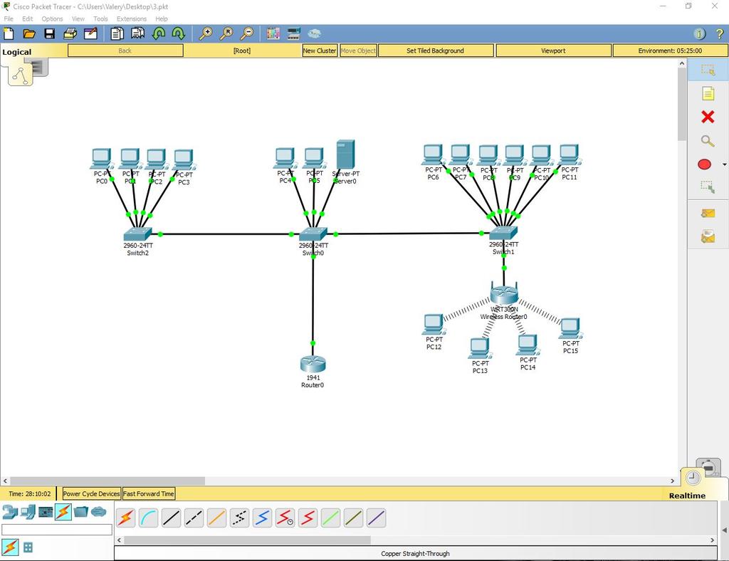
The program window and its structure are presented below.
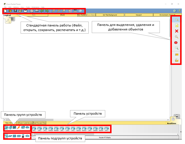
Instructions for performing laboratory work in Packet Tracer
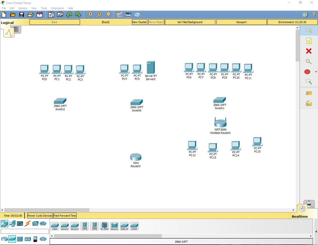
1. Adding equipment.
Open Packet Tracer and create on the working field:
a. 16 computers
b. Server
c. 3 Cisco 2960 switches
d. Cisco 1941 router
e. Cisco WRT300N router
Total: 22 devices
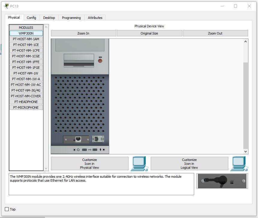
2. Install the Wi-Fi module in the PC.
In four computers in the third section, replace the LAN connector with a Wi-Fi antenna. To do this, open the device, turn it off, remove the old module, change it to a Wi-Fi (WMP300N) antenna. Turn on the computer.
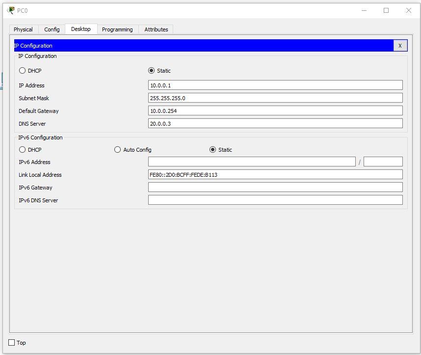
3. Setting up the PC of the first and second department.
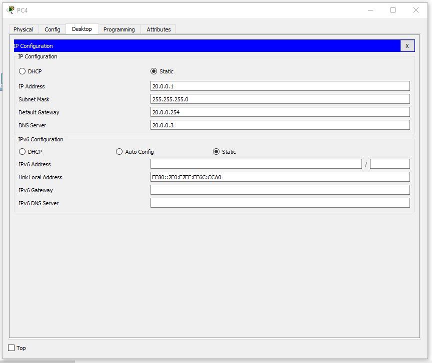
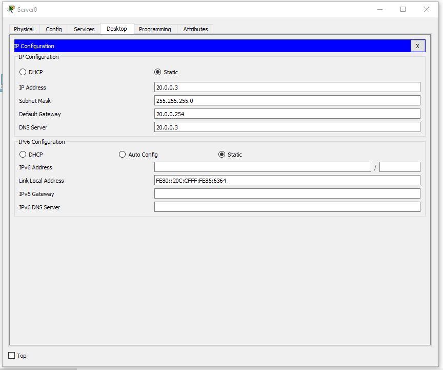
We assign values to each computer in the first and second departments, as well as to the server, using the formula: N0.0.0.n, where N is the department number and n is the device number (for example, 10.0.0.2 is the second computer on the first floor). Server, as it is the third device on the second floor will have the address 20.0.0.3.
Set the subnet mask to 255.255.255.0.
Default Gateway set N0.0.0.254.
DNS Server is set to 20.0.0.3.
An example of a correctly configured PC in the first section:
An example of a properly configured PC in the second section:
On the server, set the following settings:
4. Set up the third department.
We set the IP according to the formula 30.0.0.10n, where n is the PC number.
An example of a properly configured PC in the third section:

Continue to configure the PC. The first IP is 30.0.0.101, and the last is 30.0.0.110
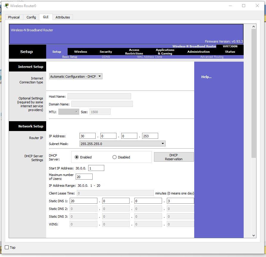
5. Configure the router.
Set the settings:
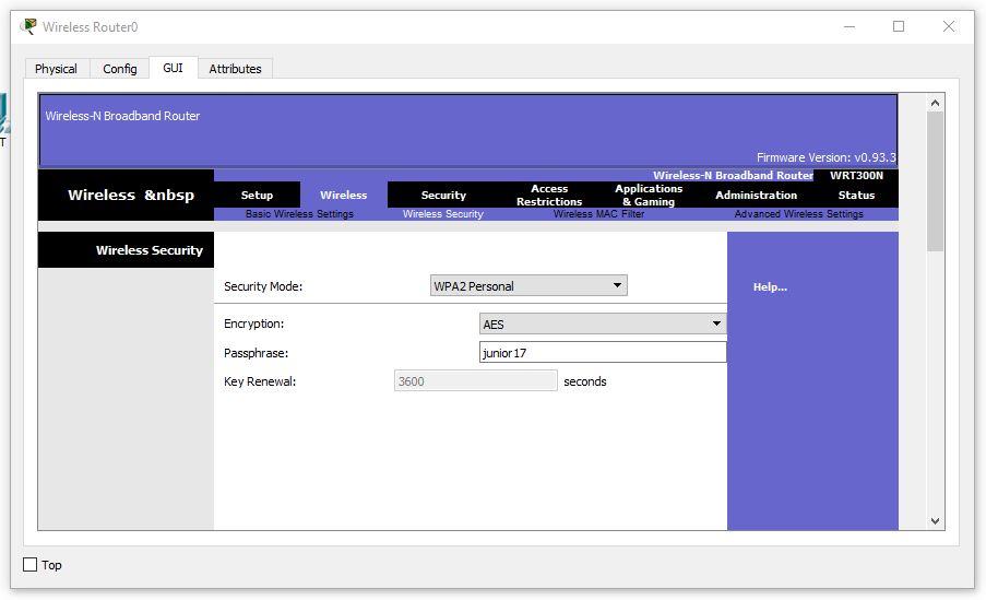
IP - 30.0.0.253 - 255.255.255.0 Start IP Address - 30.0.0.1 Maximum number of Users – 20 Static DNS 1 - 20.0.0.3 Network Name - Cisco2107 SSID Broadcast – Disabled Security Mode - WPA2-Personal Passphrase - junior17 Screenshots of all custom tabs of the router:
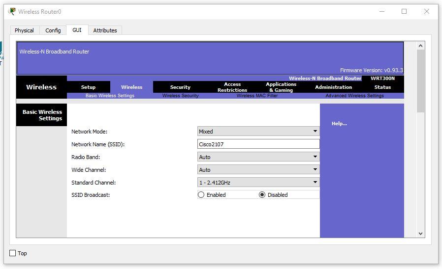
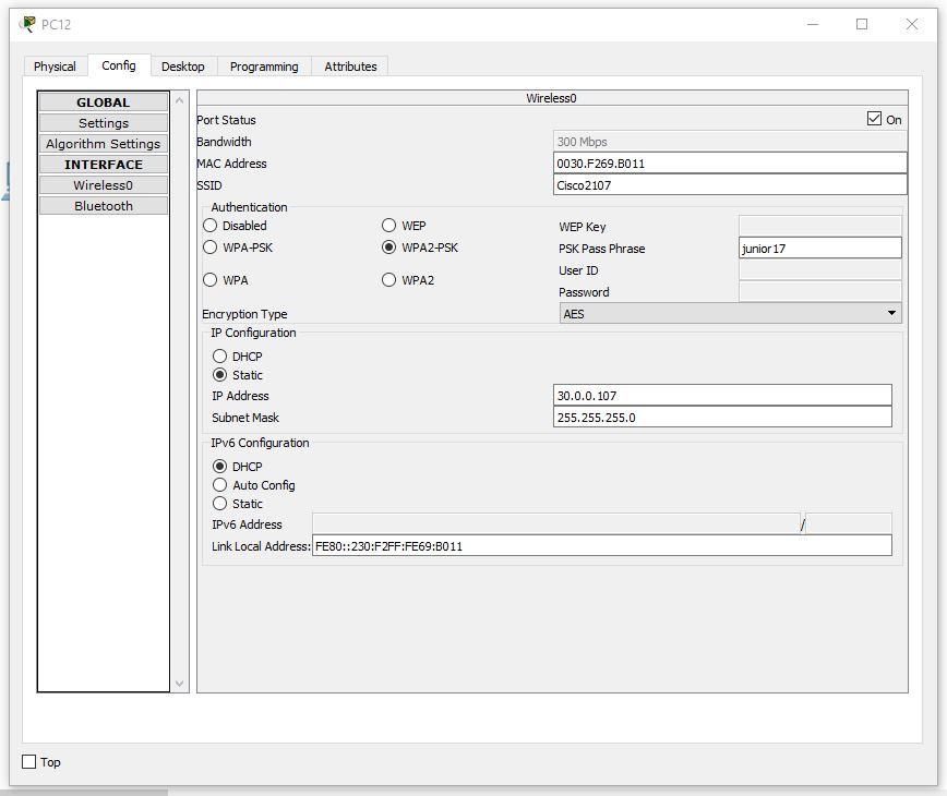
Setting up a wireless PC. Set the network name Cisco2107 and WPA2-Personal password - junior17
An example of the settings of one of the PCs:
6. We connect cables and we connect departments.
Connect the PC with a twisted pair.
In all switches, we connect cables to FastEthernet clockwise. In the router, we connect to the gigabit connector, first turning it on.
We configure VLAN on all switches. To do this, open the switch in the first section. Go to the command line interface and enter the commands:
Switch>en Switch#conf t Switch(config)#vlan 10 Switch(config-vlan)#name Office1 Switch(config-vlan)#end Consider all the commands.
- En - enable. Extended configuration access
- Conf t - Configuration terminal. Opens the terminal settings
- Vlan 10 - creates a virtual network with index 10
- Name Office1 - set the name of the VLAN. The name is Office1.
- End - completes the setup.
Open the switch in the second section and write the following commands:
Switch>en Switch#conf t Switch(config)#vlan 10 Switch(config-vlan)#name Office1 Switch(config-vlan)#exit Switch(config)#vlan 20 Switch(config-vlan)#name Office2 Switch(config-vlan)#exit Switch(config)#vlan 30 Switch(config-vlan)#name Office3 Switch(config-vlan)#exit Switch(config)#end Open the switch in the third section and write the following commands:
Switch>en Switch#conf t Switch(config)#vlan 30 Switch(config-vlan)#name Office3 Switch(config-vlan)#end We expose the VLAN 10 switch to the ports to which there is a connection (Fa0 / 1-Fa0 / 5).
On the second switch, you need to set the port to which the switch is connected from the first VLAN section - 10, from the third VLAN - 30, and 2 PCs and the server of the second VLAN department - 20. That is, Fa0 / 1 - VLAN 10, Fa0 / 2- Fa0 / 4 - VLAN 20, Fa0 / 5 - VLAN 30. Fa0 / 6, connecting the switch and the router is set to Trunk mode.
On the third switch you need to put on all ports VLAN 30 (Fa0 / 1-Fa0 / 8).
Then, we configure the router to work with VLAN.
Also, go to the CLI tab and register the commands there:
Router>en Router#conf t Router(config)#int gig 0/0.10 Router(config-subif)#encapsulation dot1Q 10 Router(config-subif)#ip address 10.0.0.254 255.255.255.0 Router(config-subif)#exit Router(config)#int gig 0/0.20 Router(config-subif)#encapsulation dot1Q 20 Router(config-subif)#ip address 20.0.0.254 255.255.255.0 Router(config-subif)#exit Router(config)#int gig 0/0.30 Router(config-subif)#encapsulation dot1Q 30 Router(config-subif)#ip address 30.0.0.254 255.255.255.0 Router(config-subif)#end Now let's sort the commands:
- int gig 0 / 0.10. The command connects the virtual interface to work with different VLANs. The digit after the dot is the VLAN number.
- Encapsulation dot1Q 10. VLAN configuration command in sub. The number after dot1Q is the VLAN number.
- ip address 10.0.0.254 255.255.255.0. IP address of the packet information.
Now let's test the network with the ping command.
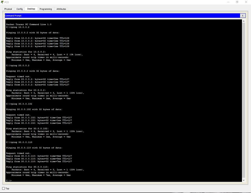
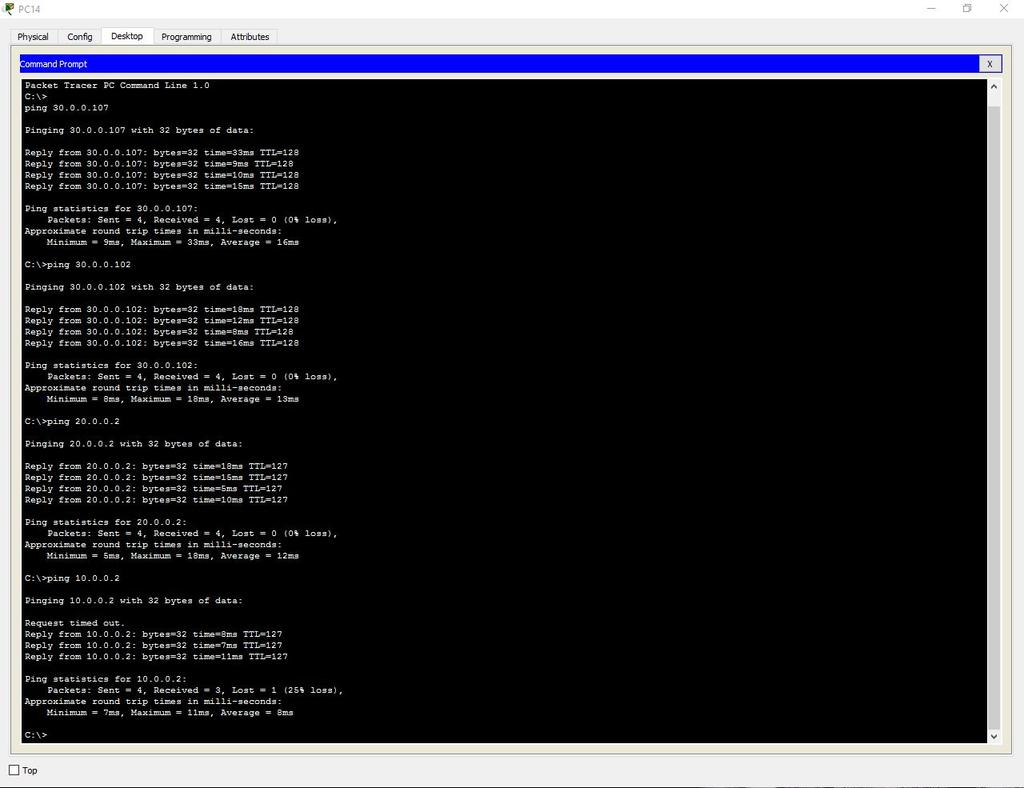
Take any computer in each department and ping all departments (in the third department, we will check both the wired network and the wireless one).
First Division
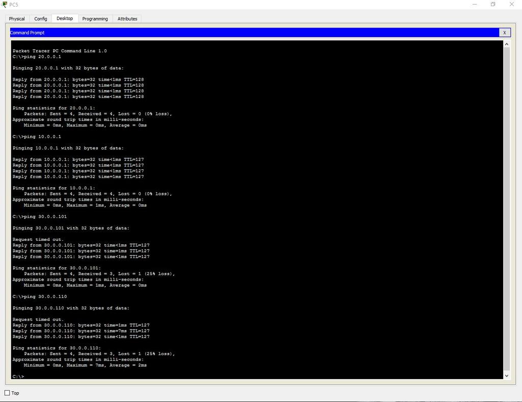
Second department
Third Division (Cable)
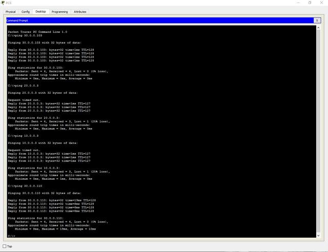
Third Division (Wi-Fi)
Add an administrative VLAN (40 - Management).
7. Configure the server.
Turn on DNS.
Name - www.cisco.com .
Address - 20.0.0.3.
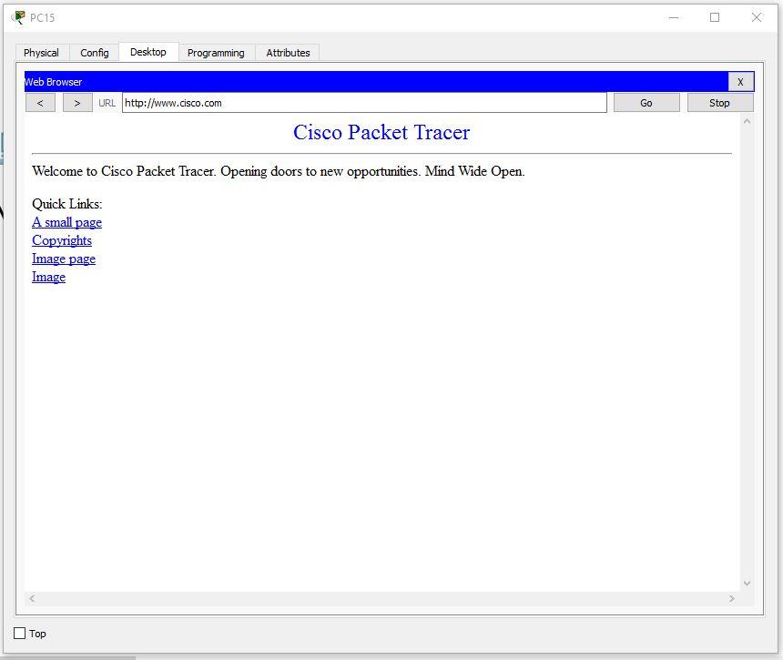
Check the possibility of access to the site from any department. Enter the URL name in the browser and click Go.
8. Configure SSH.
To do this, go to the router and write commands:
Router>en Router#clock set 10:10:00 13 Oct 2017 Router#conf t Router(config)#ip domain name ssh.dom Router(config)#crypto key generate rsa Router(config)#service password-encryption Router(config)#username Valery privilege 15 password 8 junior17 Router(config)#aaa new-model Router(config)#line vty 0 4 Router(config-line)#transport input ssh Router(config-line)#logging synchronous Router(config-line)#exec-timeout 60 0 Router(config-line)#exit Router(config)#exit Router#copy running-config startup-config We will analyze each command:
- clock set 10:10:00 13 Oct 2017. Set the exact time for key generation.
- ip domain name ssh.dom. Specify the domain name (required for key generation).
- crypto key generate rsa. We generate RSA key (it will be necessary to choose the key size).
- service password-encryption. We activate password encryption in the configuration file.
- username Valery privilege 15 password 8 junior17. We get a user with the name Valery, the password junior17 and privilege level 15.
- aaa new-model. We activate the AAA protocol (before AAA activation, at least one user must be started in the system).
- line vty 0 4. Enter the configuration mode of the terminal lines from 0 to 4.
- transport input ssh. Specify the access environment through the default network SSH.
- logging synchronous. We activate the automatic raising of the line after the system responds to the changes made.
- exec-timeout 60 0. Specify the timeout time for the automatic closing of the SSH session to 60 minutes.
- copy running-config startup-config. We save a configuration file in non-volatile memory. (The line “Destination filename [startup-config]?” Is displayed here. Enter “startup-config”).
9. Configure port protection on each switch.
To do this, open the switch and write commands:
Switch>en Switch#conf t Switch(config)#interface range fastEthernet 0/XY Switch(config-if-range)#switchport mode access Switch(config-if-range)#switchport port-security Switch(config-if-range)#switchport port-security maximum K Switch(config-if-range)#switchport port-security mac-address sticky Switch(config-if-range)#switchport port-security violation shutdown Switch(config-if-range)#end We will analyze each command:
- Interface range fastEthernet 0 / XY. Selecting a range of interfaces (X is the first required port, Y is the last).
ATTENTION! Choose ports that are NOT active in connections!- switchport mode access. We transfer port to access the mode.
- switchport port-security. Turn on port security.
- switchport port-security maximum K. Limit the number of MAC-addresses on the interface (K - the number of ports).
- switchport port-security mac-address sticky. We select the method of learning MAC addresses by the switch (there is a static (mac-address) and dynamic (sticky)).
- switchport port-security violation shutdown. We set the type of response to exceeding the number of allowed MAC addresses (there are protect - after overflow, all packets sent from other MAC addresses are discarded, the restrict is the same, but with a notification in syslog or via SNMP, shutdown - the port is turned off to automatic or manual raising it, notifications are also sent).
As a result, the work is done as follows:
Read about why this network will not be crooked to work in real conditions and how to fix it here: habrahabr.ru/post/350878
Source: https://habr.com/ru/post/350720/
All Articles