How I hacked the soldering iron
Does the phrase sound a bit strange? Thanks to the technical progress - not so long ago “taking a picture on the phone” sounded no less strange.
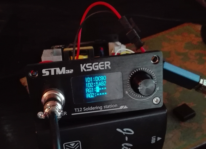
At the end of last year, I bought a soldering station, which had already received the “folk” label. Its advantages: comfortable T12 cartridge tips, decent power (up to 72W in theory), fast heating (units of seconds), low price. (You can learn more about the station in this smart review )
I bought the latest version of hardware 2.1s, and was a little upset to see that the firmware is old. Of course my hands itched to update. Knowing that the “heart” of the soldering station is STM32F103C8 (a popular ARM Cortex-M3 microprocessor from STMicroelectronics), the more interesting it was to dig, because I once blinked the LED on STM32F4Discovery.
')
4 wires of the SWD interface were soldered right there, a programmer was connected, the firmware was flooded.
And ... The station demanded activation!
To make it clearer, I will tell you a few words about the developer of this station. All information is drawn from the Internet (and, in part, from the firmware itself). Iron and firmware was developed by some Chinese comrade ZhongGuoxin (38827251@qq.com) in about 2014. The development was actively in the closed group of some Chinese forum. Apparently realizing the futility of trying to protect the development from cloning with his "fellow countrymen", he made protection in the firmware. The firmware was distributed in the form of binary modules, and it could be poured into a freshly soldered clone by anyone.
Why so? After all, there are much more reliable schemes, with the distribution of already stitched MCs and updating encrypted BLOBs. I do not know. Apparently a delicate balance between time, convenience, popularity and income. At the start, the firmware generates ID1 and ID2 codes, which the author exchanges for the activation key RG1 and RG2 for a symbolic amount of 9 yuan (~ 80 rubles).
But how can you protect the firmware if the attacker has access to it? Now we find out.
Unfortunately, my activation codes, honestly purchased with the device, I did not get. Looking ahead, I will say that, in addition to updating, a microprocessor can be soldered (if it burned its feet) or replaced with an EEPROM. And such cases have already been repeatedly.
Since I own my copy, I rightly, then in full accordance with Art. 1280 of the Civil Code, I can "carry out the actions necessary for the functioning of the program"
The firmware has been uploaded to IDA. Very quickly found a place where the activation code is entered. To make sure I'm on the right track, I patched an argument to a function that I called DisplayString. Filled the patched version. It does not start!
Well, that's okay, probably misunderstood the purpose of the function. I roll back changes. Patch text output. It does not start!
Soooo. There is an integrity check. Need a debugger. And we will catch it with a hardware breakpoint! As debuggers I went through several options, stopped at the IDA gdb + OpenOCD bundle. By itself, the debugger in IDA is inconvenient and buggy, but the ability to interactively edit dizasm directly in the debugger outweighed.
I launch OpenOCD, I set watchpoint to read the modified code bytes. I run. Watchpoint does not work ... How so? After all, 100% integrity check is present!
And here I really became interested.
The total size of the firmware is 75,512 bytes. This is quite a lot. The code for the data for us has already separated the IDA. It turned out 48128 bytes of code and 27384 bytes of data, without taking into account the small spots of local data located in the code between functions - a feature of ARM Thumb.
Now it would be nice to understand what this data means.
The simplest is text data. The names of menu items, stings, copyrights. They turned out more than 6kb. Among the texts of the menu there are bytes that are very similar to the 32-bit addresses in the FLASH segment. At these addresses, there were three-dimensional routines containing the calls to the previously found DisplayString. So this is a menu item handler. A decent amount of code identified.
We continue. Once the station screen is monochrome - it is logical to assume that the graphic data will be presented in a bit (monochrome) form. Remembering childhood with the ZX-Spectrum - it was decided to display the bytes in columns: so I was looking for graphics in games in the 90s, it was noticeably different from the data and code.
Viewbin was written on python. For convenience, each block of 256 bytes is separated from the next. Only in one column vertically exactly kilobyte is located (4 blocks). The next column refers to the next kilobyte.
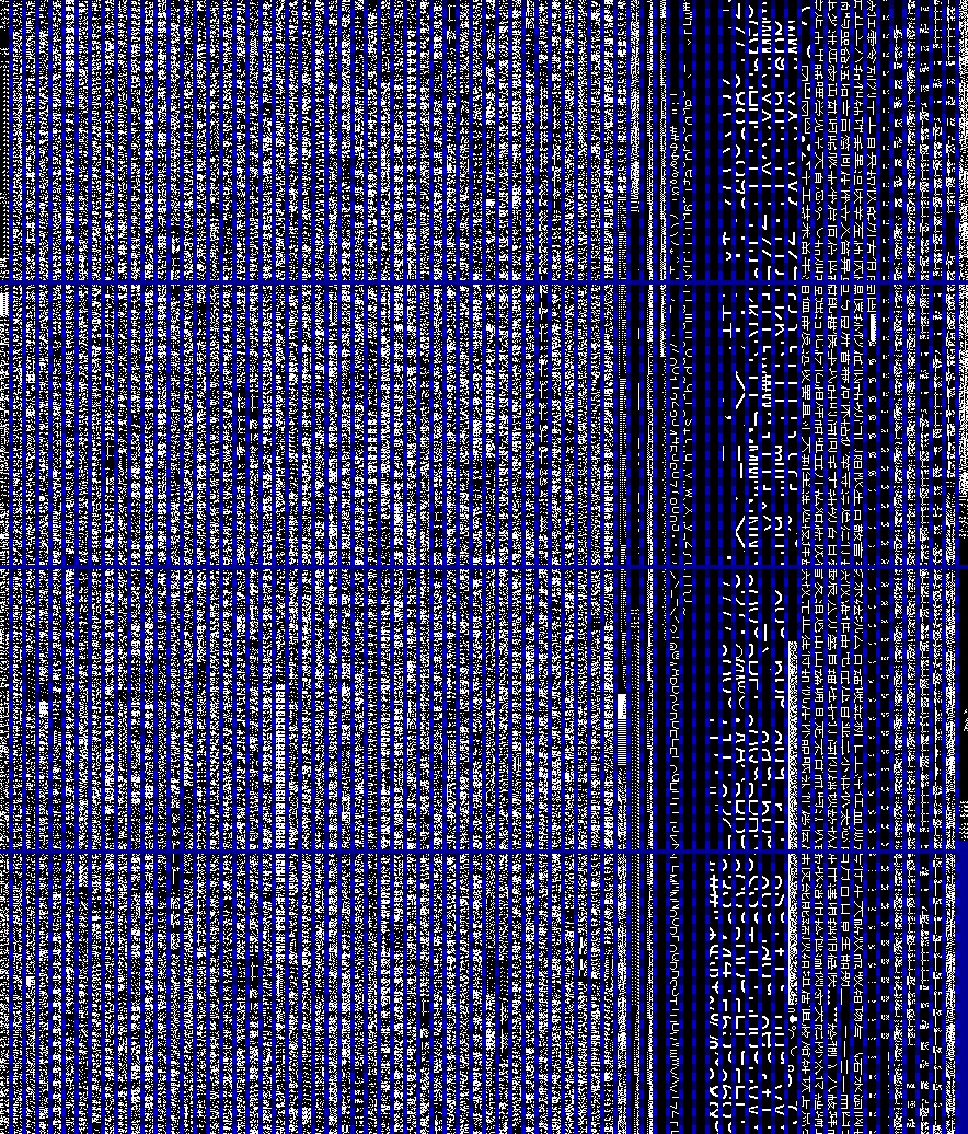
Graphic squiggles are clearly visible on the right. But in the pictures they add up badly. And if you tilt your head to the right? First, you can see the font 8 * 16 (x * y): the first 8 bytes form the upper half of the character, the second - its lower half.
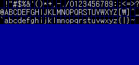
The remaining characters are built on the same principle. Large font size 16 * 32, glyphs of hieroglyphs 16 * 16
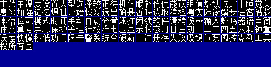
Plus there are some more service symbols (Celsius icon, thermometer, arrow, checkboxes). Totally, almost 16 kb is occupied by graphics.
Total of 27 kb of data was immediately recognized 22 kb. Not bad.
Let us turn to the code - 48 kilobytes of tight THUMB code. It is really quite compact. For example, the frequently encountered operation v1 & (~ v2) is just one “BTC” instruction.
MK, in addition to the ARM core, contains a bunch of peripheral modules. All this economy is controlled by registers mapped to memory. There are thousands of these registers. They are united in groups according to the functional attribute, each group is aligned.
Plus the so-called. BitBanding - when accessing a word (32 bit) means atomic setting or resetting a single bit . It is easy to estimate that one 32-bit register will take 128 bytes in the BitBand area. Total registers occupy the absolutely crazy size of the address space.
Working with peripherals consists in writing or reading these registers. There is a library of CMSIS from ARM, covering the bare registers with a thin layer of the SI-code and its accompanying libraries from manufacturers (STM32F10x_StdPeriph_Driver in our case) for the periphery.
From the C code, working with peripherals looks like a change in the named register of peripherals.
In assembly language, this work looks like several levels of indirect addressing. Regular CPU registers. We got r1 from r2, for it is another r0, and then again r0 at offset 0x0C. What it is is not completely clear.
After entering the registration code, several functions are called. Clears the screen. The inscription is displayed (in Chinese!). Then a few more functions are called. Two values are verified. And either one or another message is displayed (in Chinese!). Then the station hangs.
Assuming that this is the verification of the code, I replaced the condition. Nothing changed. Put breakpoints on the called functions and their internals. They are called from a large number of places with completely different arguments.
It did not become clearer. Back to the beginning. So why didn't WatchPoint count integrity monitoring?
I guessed that the reason is in the DMA (Direct Memory Access) controller. Moreover, the STM32 has a hardware CRC calculation module - you give it a task, and it reads bytes from memory through DMA, increments the address, and counts the checksum. Just wait until the end of the execution and read the result from the register.
But in order to explore the work with the periphery, it is necessary to correctly identify all the registers by their numbers. There are thousands of registers, their numerical form is hidden from the programmer by a layer of library code. In the disassembler I found a constant - look for what this register is. I got bored with datasheet-disassembler jumping. And I wrote a python script for IDA ( link to GitHub ) that generates the main mass of registers. And at the same time it defines the interrupt vector table, gives the name to the handlers, draws up the starting point and creates the SRAM segment.
It became a little clearer.
To restore the logic of work, I prefer to start with small functions. They are easier to understand, and useful ones are often used.
Functions that use a lot of bit arithmetic have been defined as Floating Point using “brute force”: the instruction pointer was placed at the beginning of the function. The registers entered the HEX floating point representation (for example, the numbers “100.0” and “30.0”). (Link to convenient Online converter ). The result of the function was converted back to a floating view. If at the exit we have something meaningful, such as "70.0" or "3.3333" - then we can safely give a name. It turned out that some of the functions work with float, part with double.
I was very lucky, and the author used the standard library to work with the periphery, the C code was ideally compared to the disassembler.
I stumbled on several noreturn functions, at the entrance to which lr pointed out “out of sight”, having the value 0xFFFFFFFF, and the stack was filled with strange constants like 0x12121212, 0x09090909. Google insisted that it was FreeRTOS (What ?!
Real-Time Operating System at ... CANNER?).
But the binary code could not be compared with the source code. I checked 10 versions, from 10.0.0 (2018) to 3.2.4 (2005). Everywhere the similarity was only superficial. Therefore, I limited myself to naming such functions as TaskXXXXX, and the general code that passed control to them, like TaskCreate.
Among the recognized functions of the standard library were DMAInit, DMACmd, DMAGetCurrentDataCounter. The problem was that they were called too much and often. And I'm lazy.
Therefore, I wrote a python API for working with OpenOCD functions: Link to GitHub . Commands are sent to the OpenOCD server via telnet protocol. As an example of use in the “examples / dbgbot” directory there is a robot code, which will be discussed below.
Based on this API, I made a robot exploring DMA calls. The robot responds to the initialization of the DMA operation in the DMA_Init function. It records the addresses of the periphery, the memory, the direction of transmission, the number and size of the transmitted elements, as well as the optional sign of autoincrement of the source and destination addresses.
But besides that, I wanted to see the data being received. For example, if a CRC calculation is requested, then I want to know exactly what counted there. To do this, you need to go through the whole chain of calls: Init -> Command “enable” -> Wait. Those. need a state machine. Which dynamically sets and removes breakpoints depending on the position between states.
For Wait, you have to wait for the hardware counter to reset. (There is also an alarm with interrupts, but this is not our case.) You have to wait while continuing to execute commands, since JTAG debugging completely stops the microprocessor core.
The problem turned out to be that the author did not bother with waiting, if he gave the DMA a command for a small amount of data - by the time they became needed, the chip had already done everything. For me, this decision meant that I could not hope to call DMAGetCurrentDataCounter to track the end of the transfer. And when I started to use this data, I didn’t know either - if it is too late to receive them, they may already be spoiled by the work of the rest of the code.
Therefore, heuristics had to be applied: if the transfer size is> 32 bytes, an explicit check will be used. Otherwise, after issuing the transfer command, I will step by step perform as many instructions as requested by the transfer.
This is not the only “hack” - after examining the whole code of expectations, I came to the conclusion that it always takes 4 bytes after calling DMAGetCurrentDataCounter.
Therefore, after the first triggering of this breakpoint, we get the return address and rearrange the breakpoint by 4 bytes after it. Waiting is complete!
Video of the robot with the analysis of DMA operations:
The functions related to the CRC count turned out to be 8 (EIGHT!). Neither contains explicit parameters, ornate calculations are used. Some of these functions use recursion to calculate, which further complicates understanding.
From the dump made by the robot, it is clearly seen that the constant (I called it MasterCRC) is copied from Flash to RAM, then from RAM to RAM. CRC is considered to be in two halves of a flush: before this constant and after this constant until the very end, i.e. even on the unallocated area. This means that if the chip is not pre-cleaned before flashing, the checksum will not converge!
A complete CRC calculation is performed 4 times. Horror! Then it counts CRC on CRC. And CRC on CRC on CRC. Horror! I didn’t go deep into manipulating CRC.
In addition to counting the CRC and strange movements from memory to memory, the log turned out to have a unique chip ID. Using DMA. This is very suspicious, because The ID of the chip is set during production, it is unique for each crystal - an excellent candidate for the role of data source for the formation of regcode.
The suspicion was confirmed - the calls returned my ID1 and ID2 codes.
Defining functions from the standard peripheral library, I noticed that the strange table was being processed at 0x800C23C. It describes the state of each of the 16 pins of all 7 GPIO ports (calls - a creepy copy-paste). It became interesting what pins are used for.
Pay attention to the connection of the EEPROM Flash. I2C lines are wound up where there is no I2C hardware. A strange decision, isn't it?
Well, so much the better. I have never worked with I2C. And then there was such an opportunity to touch him at the level of manual control of the signals on the legs of the MK! I downloaded the dock from the TI website, drew a state table, sketched the code for the robot. So that he can decode the transmission according to the changes of the pins.
And then I was waiting for a bummer. EEPROM does not stop the debugger. And although theoretically she could have waited for the master, in practice everything falls apart completely.
Ok, knowing the operation of the protocol, we give the names to the functions, going up level by level to a bunch of Flash_ReadData / Flash_WriteData functions that differ little from each other (copy-paste?)
I look at the links - reading and writing is called from the place where the code is entered. Interesting! It turns out 4 byte response code after input is written in flash. And then read from there. Waiting for these operations I took for checking. And two different messages in Chinese - if they read the same as they did and if not (hardware error?).
It turns out that after entering the code is not checked. It is always checked at the start of the station. And if the verification fails, instead of the main RTOS task of the soldering iron, another RTOS task is created, which deals with entering the code and writing it to the flash. Well, it is logical.
In addition, read-write of a solid piece of data occurs in the adjacent flash functions. Size 0x3AE bytes. It looks like the settings. After reading them, the function of calculating the code from the buffer with data is called. Before the dental gnash resembles the function of calculating the ID1 and ID2. And even the data table is another one, exactly the same. Why use this code to check the integrity of the settings? Would take a better CRC! Wait, what if ...? I push the constants from the table into Google - exactly. This is the CRC. More precisely CRC16_CCIT. Two copies of the same function. Two copies of the tables. To the enemy did not guess.
So, we control reading from a flash. "Reset init". The breakpoint quickly leads us to the place where the newly recorded response is read. We put a watchpoint on the read data. “Resume” The station shows the code entry interface as if nothing had happened.
DMA again? We look at the log. Immediately after copying the read code from the flash, two blocks of 32 bytes are copied. We look disassembler at the return address from the DMA operation. In the code we see after copying 32 bytes a call to a strange function with a bunch of xor inside. Put a breakpoint.
When calling a function, we see a buffer with some data, in the last 4 bytes of which the already familiar ID1 and ID2 stations lie. At the exit of the function we see a 16 bit number. Another call is a buffer with other data, at the end ID1 and ID2 are also located.
It remains to understand exactly what this mysterious function calculates. And she does this:
It seems that the original table was cut into pieces of 8 elements, mixed, and glued together again. For example, the first piece was 0th. The 5th has not gone away. And on the 4th place is now the 31st. We write a short code for comparison, and here are the necessary permutations for assembling this strange table: 1, 2, 3, 4, 31, 5, 6, 7, 8, 9, 10, 11, 12, 0, 13, 25, 14, 15, 16, 17, 18, 19, 20, 21, 22, 23, 24, 26, 27, 28, 29, 30.
Rewritable in Python. Check - works. For debugging, I asked a few guys from the Internet, having the same stations, to give me their ID and check the generated RGs. Checked for another 5 stations. The result is correct.
And if protection would be simpler? Probably would have entered the code, and forgot about it ...
Write in the comments if you are interested in finding out the continuation of the story: the reverse of the algorithms of the soldering station and the development of my version.
PS: Specially for this article rewrote the key generation code in javascript. Online version , there is also a link to the Python version. If the explanations were somewhere incomprehensible - you can learn the details from the code. And, of course, to revive your own station, blocked by updating or repairing iron.
At the end of last year, I bought a soldering station, which had already received the “folk” label. Its advantages: comfortable T12 cartridge tips, decent power (up to 72W in theory), fast heating (units of seconds), low price. (You can learn more about the station in this smart review )
I bought the latest version of hardware 2.1s, and was a little upset to see that the firmware is old. Of course my hands itched to update. Knowing that the “heart” of the soldering station is STM32F103C8 (a popular ARM Cortex-M3 microprocessor from STMicroelectronics), the more interesting it was to dig, because I once blinked the LED on STM32F4Discovery.
')
4 wires of the SWD interface were soldered right there, a programmer was connected, the firmware was flooded.
And ... The station demanded activation!
To make it clearer, I will tell you a few words about the developer of this station. All information is drawn from the Internet (and, in part, from the firmware itself). Iron and firmware was developed by some Chinese comrade ZhongGuoxin (38827251@qq.com) in about 2014. The development was actively in the closed group of some Chinese forum. Apparently realizing the futility of trying to protect the development from cloning with his "fellow countrymen", he made protection in the firmware. The firmware was distributed in the form of binary modules, and it could be poured into a freshly soldered clone by anyone.
Why so? After all, there are much more reliable schemes, with the distribution of already stitched MCs and updating encrypted BLOBs. I do not know. Apparently a delicate balance between time, convenience, popularity and income. At the start, the firmware generates ID1 and ID2 codes, which the author exchanges for the activation key RG1 and RG2 for a symbolic amount of 9 yuan (~ 80 rubles).
But how can you protect the firmware if the attacker has access to it? Now we find out.
Unfortunately, my activation codes, honestly purchased with the device, I did not get. Looking ahead, I will say that, in addition to updating, a microprocessor can be soldered (if it burned its feet) or replaced with an EEPROM. And such cases have already been repeatedly.
Since I own my copy, I rightly, then in full accordance with Art. 1280 of the Civil Code, I can "carry out the actions necessary for the functioning of the program"
The first pancake is lumpy
The firmware has been uploaded to IDA. Very quickly found a place where the activation code is entered. To make sure I'm on the right track, I patched an argument to a function that I called DisplayString. Filled the patched version. It does not start!
Well, that's okay, probably misunderstood the purpose of the function. I roll back changes. Patch text output. It does not start!
Soooo. There is an integrity check. Need a debugger. And we will catch it with a hardware breakpoint! As debuggers I went through several options, stopped at the IDA gdb + OpenOCD bundle. By itself, the debugger in IDA is inconvenient and buggy, but the ability to interactively edit dizasm directly in the debugger outweighed.
I launch OpenOCD, I set watchpoint to read the modified code bytes. I run. Watchpoint does not work ... How so? After all, 100% integrity check is present!
And here I really became interested.
Examine the data
The total size of the firmware is 75,512 bytes. This is quite a lot. The code for the data for us has already separated the IDA. It turned out 48128 bytes of code and 27384 bytes of data, without taking into account the small spots of local data located in the code between functions - a feature of ARM Thumb.
Now it would be nice to understand what this data means.
The simplest is text data. The names of menu items, stings, copyrights. They turned out more than 6kb. Among the texts of the menu there are bytes that are very similar to the 32-bit addresses in the FLASH segment. At these addresses, there were three-dimensional routines containing the calls to the previously found DisplayString. So this is a menu item handler. A decent amount of code identified.
We continue. Once the station screen is monochrome - it is logical to assume that the graphic data will be presented in a bit (monochrome) form. Remembering childhood with the ZX-Spectrum - it was decided to display the bytes in columns: so I was looking for graphics in games in the 90s, it was noticeably different from the data and code.
Viewbin was written on python. For convenience, each block of 256 bytes is separated from the next. Only in one column vertically exactly kilobyte is located (4 blocks). The next column refers to the next kilobyte.
Graphic squiggles are clearly visible on the right. But in the pictures they add up badly. And if you tilt your head to the right? First, you can see the font 8 * 16 (x * y): the first 8 bytes form the upper half of the character, the second - its lower half.
The remaining characters are built on the same principle. Large font size 16 * 32, glyphs of hieroglyphs 16 * 16
Plus there are some more service symbols (Celsius icon, thermometer, arrow, checkboxes). Totally, almost 16 kb is occupied by graphics.
Total of 27 kb of data was immediately recognized 22 kb. Not bad.
Let us turn to the code - 48 kilobytes of tight THUMB code. It is really quite compact. For example, the frequently encountered operation v1 & (~ v2) is just one “BTC” instruction.
What is ARM Cortex M3
MK, in addition to the ARM core, contains a bunch of peripheral modules. All this economy is controlled by registers mapped to memory. There are thousands of these registers. They are united in groups according to the functional attribute, each group is aligned.
Plus the so-called. BitBanding - when accessing a word (32 bit) means atomic setting or resetting a single bit . It is easy to estimate that one 32-bit register will take 128 bytes in the BitBand area. Total registers occupy the absolutely crazy size of the address space.
Working with peripherals consists in writing or reading these registers. There is a library of CMSIS from ARM, covering the bare registers with a thin layer of the SI-code and its accompanying libraries from manufacturers (STM32F10x_StdPeriph_Driver in our case) for the periphery.
From the C code, working with peripherals looks like a change in the named register of peripherals.
In assembly language, this work looks like several levels of indirect addressing. Regular CPU registers. We got r1 from r2, for it is another r0, and then again r0 at offset 0x0C. What it is is not completely clear.
Examine the code
After entering the registration code, several functions are called. Clears the screen. The inscription is displayed (in Chinese!). Then a few more functions are called. Two values are verified. And either one or another message is displayed (in Chinese!). Then the station hangs.
Assuming that this is the verification of the code, I replaced the condition. Nothing changed. Put breakpoints on the called functions and their internals. They are called from a large number of places with completely different arguments.
It did not become clearer. Back to the beginning. So why didn't WatchPoint count integrity monitoring?
I guessed that the reason is in the DMA (Direct Memory Access) controller. Moreover, the STM32 has a hardware CRC calculation module - you give it a task, and it reads bytes from memory through DMA, increments the address, and counts the checksum. Just wait until the end of the execution and read the result from the register.
But in order to explore the work with the periphery, it is necessary to correctly identify all the registers by their numbers. There are thousands of registers, their numerical form is hidden from the programmer by a layer of library code. In the disassembler I found a constant - look for what this register is. I got bored with datasheet-disassembler jumping. And I wrote a python script for IDA ( link to GitHub ) that generates the main mass of registers. And at the same time it defines the interrupt vector table, gives the name to the handlers, draws up the starting point and creates the SRAM segment.
It became a little clearer.
To restore the logic of work, I prefer to start with small functions. They are easier to understand, and useful ones are often used.
Functions that use a lot of bit arithmetic have been defined as Floating Point using “brute force”: the instruction pointer was placed at the beginning of the function. The registers entered the HEX floating point representation (for example, the numbers “100.0” and “30.0”). (Link to convenient Online converter ). The result of the function was converted back to a floating view. If at the exit we have something meaningful, such as "70.0" or "3.3333" - then we can safely give a name. It turned out that some of the functions work with float, part with double.
I was very lucky, and the author used the standard library to work with the periphery, the C code was ideally compared to the disassembler.
I stumbled on several noreturn functions, at the entrance to which lr pointed out “out of sight”, having the value 0xFFFFFFFF, and the stack was filled with strange constants like 0x12121212, 0x09090909. Google insisted that it was FreeRTOS (What ?!
Real-Time Operating System at ... CANNER?).
But the binary code could not be compared with the source code. I checked 10 versions, from 10.0.0 (2018) to 3.2.4 (2005). Everywhere the similarity was only superficial. Therefore, I limited myself to naming such functions as TaskXXXXX, and the general code that passed control to them, like TaskCreate.
We investigate work of the periphery or Automation of debugging
Among the recognized functions of the standard library were DMAInit, DMACmd, DMAGetCurrentDataCounter. The problem was that they were called too much and often. And I'm lazy.
Therefore, I wrote a python API for working with OpenOCD functions: Link to GitHub . Commands are sent to the OpenOCD server via telnet protocol. As an example of use in the “examples / dbgbot” directory there is a robot code, which will be discussed below.
Based on this API, I made a robot exploring DMA calls. The robot responds to the initialization of the DMA operation in the DMA_Init function. It records the addresses of the periphery, the memory, the direction of transmission, the number and size of the transmitted elements, as well as the optional sign of autoincrement of the source and destination addresses.
But besides that, I wanted to see the data being received. For example, if a CRC calculation is requested, then I want to know exactly what counted there. To do this, you need to go through the whole chain of calls: Init -> Command “enable” -> Wait. Those. need a state machine. Which dynamically sets and removes breakpoints depending on the position between states.
For Wait, you have to wait for the hardware counter to reset. (There is also an alarm with interrupts, but this is not our case.) You have to wait while continuing to execute commands, since JTAG debugging completely stops the microprocessor core.
The problem turned out to be that the author did not bother with waiting, if he gave the DMA a command for a small amount of data - by the time they became needed, the chip had already done everything. For me, this decision meant that I could not hope to call DMAGetCurrentDataCounter to track the end of the transfer. And when I started to use this data, I didn’t know either - if it is too late to receive them, they may already be spoiled by the work of the rest of the code.
Therefore, heuristics had to be applied: if the transfer size is> 32 bytes, an explicit check will be used. Otherwise, after issuing the transfer command, I will step by step perform as many instructions as requested by the transfer.
This is not the only “hack” - after examining the whole code of expectations, I came to the conclusion that it always takes 4 bytes after calling DMAGetCurrentDataCounter.
Therefore, after the first triggering of this breakpoint, we get the return address and rearrange the breakpoint by 4 bytes after it. Waiting is complete!
DMA operations log
??? DMA LR:0x08000abf P:0x4001244c *(00000000) (=>) M:0x20000224 [0x000f] P2.M2+
-------------------------------------------------------------------------------------
MasterCRCtoRAM
M2M DMA LR:0x08002e81 P:0x080125bc *(145eac33) (=>) M:0x200000f0 [0x0002] P2+M2+
-------------------------------------------------------------------------------------
MasterCRCtoRAM
M2M DMA LR:0x08002e81 P:0x080125bc *(145eac33) (=>) M:0x20000020 [0x0002] P2+M2+
-------------------------------------------------------------------------------------
Calc_CRC_0_Wrap (Begin)
M2M DMA LR:0x08005001 P:0x200000f0 *(145eac33) (=>) M:0x20000010 [0x0002] P2+M2+
-------------------------------------------------------------------------------------
Calc_CRC_0
CRC DMA LR:0x080050d3 P:0x40023008 (<=) M:0x2000085c *(00000001) [0x0001] P4.M4.
CRC DMA LR:0x08005127 P:0x40023000 (<=) M:0x20000010 *(145eac33) [0x0002] P4.M4.
CRC DMA LR:0x08005127 P:0x40023000 (<=) M:0x20000010 *(145eac33) [0x0002] P4.M4.
CRC DMA LR:0x08005177 P:0x40023000 *(abb10a5e) (=>) M:0x20000010 [0x0001] P4.M4.
-------------------------------------------------------------------------------------
Calc_CRC_0_Wrap (End)
M2M DMA LR:0x08005043 P:0x200000f0 *(145eac33) (=>) M:0x20000014 [0x0002] P2+M2+
-------------------------------------------------------------------------------------
Calc_CRC_1
CRC DMA LR:0x08005203 P:0x40023008 (<=) M:0x20000804 *(00000001) [0x0001] P4.M4.
CRC DMA LR:0x08005257 P:0x40023000 (<=) M:0x20000014 *(145eac33) [0x0006] P4.M4.
CRC DMA LR:0x08005257 P:0x40023000 (<=) M:0x20000014 *(145eac33) [0x0006] P4.M4.
CRC DMA LR:0x08005257 P:0x40023000 (<=) M:0x20000014 *(145eac33) [0x0006] P4.M4.
CRC DMA LR:0x080052a7 P:0x40023000 *(4859bef2) (=>) M:0x20000014 [0x0001] P4.M4.
-------------------------------------------------------------------------------------
Calc_CRC_2
CRC DMA LR:0x08002359 P:0x40023008 (<=) M:0x20000954 *(00000001) [0x0001] P4.M4.
CRC DMA LR:0x080023ad P:0x40023000 (<=) M:0x08000000 [0x496f] P4.M4+
CRC DMA LR:0x08002411 P:0x40023000 (<=) M:0x080125c0 [0x3690] P4.M4+
CRC DMA LR:0x08002463 P:0x40023000 *(145eac33) (=>) M:0x2000001c [0x0001] P4.M4.
CRC DMA LR:0x080024b5 P:0x40023000 *(145eac33) (=>) M:0x20000958 [0x0001] P4.M4.
-------------------------------------------------------------------------------------
Calc_CRC_3
CRC DMA LR:0x08002f07 P:0x40023008 (<=) M:0x2000095c *(00000001) [0x0001] P4.M4.
CRC DMA LR:0x08002f5d P:0x40023000 (<=) M:0x08000000 [0x496f] P4.M4+
CRC DMA LR:0x08002fbf P:0x40023000 (<=) M:0x080125c0 [0x3690] P4.M4+
CRC DMA LR:0x08003011 P:0x40023000 *(145eac33) (=>) M:0x20000030 [0x0001] P4.M4.
-------------------------------------------------------------------------------------
Calc_CRC_4
CRC DMA LR:0x08002c17 P:0x40023008 (<=) M:0x20000854 *(00000001) [0x0001] P4.M4.
CRC DMA LR:0x08002c6b P:0x40023000 (<=) M:0x20000030 *(145eac33) [0x0002] P4.M4.
CRC DMA LR:0x08002c6b P:0x40023000 (<=) M:0x20000030 *(145eac33) [0x0002] P4.M4.
CRC DMA LR:0x08002cbb P:0x40023000 *(abb10a5e) (=>) M:0x20000030 [0x0001] P4.M4.
-------------------------------------------------------------------------------------
Calc_CRC_5
CRC DMA LR:0x080030bb P:0x40023008 (<=) M:0x2000095c *(00000001) [0x0001] P4.M4.
CRC DMA LR:0x08003111 P:0x40023000 (<=) M:0x08000000 [0x496f] P4.M4+
CRC DMA LR:0x08003173 P:0x40023000 (<=) M:0x080125c0 [0x3690] P4.M4+
CRC DMA LR:0x080031c5 P:0x40023000 *(145eac33) (=>) M:0x20000034 [0x0001] P4.M4.
-------------------------------------------------------------------------------------
Calc_CRC_6
CRC DMA LR:0x08002d47 P:0x40023008 (<=) M:0x200007fc *(00000001) [0x0001] P4.M4.
CRC DMA LR:0x08002d9b P:0x40023000 (<=) M:0x20000034 *(145eac33) [0x0006] P4.M4.
CRC DMA LR:0x08002d9b P:0x40023000 (<=) M:0x20000034 *(145eac33) [0x0006] P4.M4.
CRC DMA LR:0x08002d9b P:0x40023000 (<=) M:0x20000034 *(145eac33) [0x0006] P4.M4.
CRC DMA LR:0x08002deb P:0x40023000 *(4859bef2) (=>) M:0x20000034 [0x0001] P4.M4.
-------------------------------------------------------------------------------------
Calc_CRC_2
CRC DMA LR:0x08002359 P:0x40023008 (<=) M:0x20000c64 *(00000001) [0x0001] P4.M4.
CRC DMA LR:0x080023ad P:0x40023000 (<=) M:0x08000000 [0x496f] P4.M4+
CRC DMA LR:0x08002411 P:0x40023000 (<=) M:0x080125c0 [0x3690] P4.M4+
CRC DMA LR:0x08002463 P:0x40023000 *(145eac33) (=>) M:0x2000001c [0x0001] P4.M4.
CRC DMA LR:0x080024b5 P:0x40023000 *(145eac33) (=>) M:0x20000c68 [0x0001] P4.M4.
-------------------------------------------------------------------------------------
Calc_CRC_7
CRC DMA LR:0x08007a7d P:0x40023008 (<=) M:0x200008a0 *(00000001) [0x0001] P4.M4.
CRC DMA LR:0x08007acd P:0x40023000 (<=) M:0x200000fc *(abcdfedc) [0x0076] P4.M4.
CRC DMA LR:0x08007acd P:0x40023000 (<=) M:0x200000fc *(abcdfedc) [0x0076] P4.M4.
CRC DMA LR:0x08007b1f P:0x40023000 *(80a34f2a) (=>) M:0x200000fc [0x0001] P4.M4.
-------------------------------------------------------------------------------------
DMACopyWord_0
M2M DMA LR:0x08002b09 P:0x200000fc *(80a34f2a) (=>) M:0x20000000 [0x0002] P2+M2+
-------------------------------------------------------------------------------------
DMACopyWord_1
M2M DMA LR:0x08002b91 P:0x200000fc *(80a34f2a) (=>) M:0x200000f4 [0x0002] P2+M2+
-------------------------------------------------------------------------------------
Get_DesignID_0
M2M DMA LR:0x080029f3 P:0x1ffff7e8 (=>) M:0x200021c0 [0x0006] P2+M2+
0x200021c0 56 ff 76 06 51 80 48 54 | 38 18 10 87 VvQHT8 ...
-------------------------------------------------------------------------------------
DMACopyWord_2
M2M DMA LR:0x08002a7f P:0x20000000 *(80a34f2a) (=>) M:0x200001b0 [0x0002] P2+M2+
-------------------------------------------------------------------------------------
Get_DesignID_1
M2M DMA LR:0x08001c61 P:0x1ffff7e8 (=>) M:0x20002dc0 [0x0006] P2+M2+
0x20002dc0 56 ff 76 06 51 80 48 54 | 38 18 10 87 VvQHT8 ...
M2M DMA LR:0x08001cc5 P:0x200001b0 *(80a34f2a) (=>) M:0x20002db8 [0x0002] P2+M2+
-------------------------------------------------------------------------------------
Calc_CRC_7_Wrap (Begin)
M2M DMA LR:0x08001d99 P:0x200030b8 *(5a92dc90) (=>) M:0x200030c4 [0x0002] P2+M2+
M2M DMA LR:0x08001dd5 P:0x0800f4bb (=>) M:0x20003098 [0x0010] P2+M2+
0x20003090 | 00 04 04 44 c4 4f 44 44 . ..D.ODD
0x200030a0 c4 24 24 2f b4 24 04 04 | 00 40 44 24 24 15 0c 04 .$$/.$... @D$$...
0x200030b0 fe 04 0c 15 24 24 44 40 | ....$$D@
M2M DMA LR:0x08001e2f P:0x0800f4fb (=>) M:0x20003098 [0x000e] P2+M2+
0x20003090 | 00 10 60 02 8c 00 00 fe . .`.....
0x200030a0 92 92 92 92 92 fe 00 00 | 00 04 04 7e 01 40 7e 42 ......... ..~.@~B
0x200030b0 42 7e 42 7e | B~B~
-------------------------------------------------------------------------------------
Calc_CRC_7
CRC DMA LR:0x08007a7d P:0x40023008 (<=) M:0x20002f84 *(00000001) [0x0001] P4.M4.
CRC DMA LR:0x08007acd P:0x40023000 (<=) M:0x200030c8 *(a7894d6e) [0x0076] P4.M4.
CRC DMA LR:0x08007acd P:0x40023000 (<=) M:0x200030c8 *(a7894d6e) [0x0076] P4.M4.
CRC DMA LR:0x08007b1f P:0x40023000 *(fab893e0) (=>) M:0x200030c8 [0x0001] P4.M4.
-------------------------------------------------------------------------------------
Calc_CRC_7_Wrap (End)
M2M DMA LR:0x08001e81 P:0x200030c8 *(fab893e0) (=>) M:0x200000f8 [0x0002] P2+M2+
M2M DMA LR:0x08001ebd P:0x200030c8 *(fab893e0) (=>) M:0x200030bc [0x0002] P2+M2+
-------------------------------------------------------------------------------------
DMACopy_32bytes_0
M2M DMA LR:0x08001b73 P:0x0800f4bb (=>) M:0x20002778 [0x0010] P2+M2+
0x20002770 | 00 04 04 44 c4 4f 44 44 . ..D.ODD
0x20002780 c4 24 24 2f b4 24 04 04 | 00 40 44 24 24 15 0c 04 .$$/.$... @D$$...
0x20002790 fe 04 0c 15 24 24 44 40 | ....$$D@
-------------------------------------------------------------------------------------
DMACopy_32bytes_1
M2M DMA LR:0x08001be7 P:0x0800f4fb (=>) M:0x20002778 [0x0010] P2+M2+
0x20002770 | 00 10 60 02 8c 00 00 fe . .`.....
0x20002780 92 92 92 92 92 fe 00 00 | 00 04 04 7e 01 40 7e 42 ......... ..~.@~B
0x20002790 42 7e 42 7e 42 42 7e 40 | B~B~BB~@
-------------------------------------------------------------------------------------
Calc_CRC_7
CRC DMA LR:0x08007a7d P:0x40023008 (<=) M:0x200026bc *(00000001) [0x0001] P4.M4.
CRC DMA LR:0x08007acd P:0x40023000 (<=) M:0x200027a4 *(a7894d6e) [0x0076] P4.M4.
CRC DMA LR:0x08007acd P:0x40023000 (<=) M:0x200027a4 *(a7894d6e) [0x0076] P4.M4.
CRC DMA LR:0x08007b1f P:0x40023000 *(fab893e0) (=>) M:0x200027a4 [0x0001] P4.M4.
-------------------------------------------------------------------------------------
DMACopy_32bytes_0
M2M DMA LR:0x08001b73 P:0x0800f4bb (=>) M:0x20002a80 [0x0010] P2+M2+
0x20002a80 00 04 04 44 c4 4f 44 44 | c4 24 24 2f b4 24 04 04 ...D.ODD. $$/.$..
0x20002a90 00 40 44 24 24 15 0c 04 | fe 04 0c 15 24 24 44 40 .@D$$.... ...$$D@
-------------------------------------------------------------------------------------
DMACopy_32bytes_1
M2M DMA LR:0x08001be7 P:0x0800f4fb (=>) M:0x20002a80 [0x0010] P2+M2+
0x20002a80 00 10 60 02 8c 00 00 fe 92 | 92 92 92 92 fe 00 00 ..`...... .......
0x20002a90 00 04 04 7e 01 40 7e 42 42 | 7e 42 7e 42 42 7e 40 ...~.@~BB ~B~BB~@
-------------------------------------------------------------------------------------
Calc_CRC_7
CRC DMA LR:0x08007a7d P:0x40023008 (<=) M:0x200029c4 *(00000001) [0x0001] P4.M4.
CRC DMA LR:0x08007acd P:0x40023000 (<=) M:0x20002aac *(a7894d6e) [0x0076] P4.M4.
CRC DMA LR:0x08007acd P:0x40023000 (<=) M:0x20002aac *(a7894d6e) [0x0076] P4.M4.
CRC DMA LR:0x08007b1f P:0x40023000 *(fab893e0) (=>) M:0x20002aac [0x0001] P4.M4.
Video of the robot with the analysis of DMA operations:
The functions related to the CRC count turned out to be 8 (EIGHT!). Neither contains explicit parameters, ornate calculations are used. Some of these functions use recursion to calculate, which further complicates understanding.
From the dump made by the robot, it is clearly seen that the constant (I called it MasterCRC) is copied from Flash to RAM, then from RAM to RAM. CRC is considered to be in two halves of a flush: before this constant and after this constant until the very end, i.e. even on the unallocated area. This means that if the chip is not pre-cleaned before flashing, the checksum will not converge!
A complete CRC calculation is performed 4 times. Horror! Then it counts CRC on CRC. And CRC on CRC on CRC. Horror! I didn’t go deep into manipulating CRC.
DMA brings the first success
In addition to counting the CRC and strange movements from memory to memory, the log turned out to have a unique chip ID. Using DMA. This is very suspicious, because The ID of the chip is set during production, it is unique for each crystal - an excellent candidate for the role of data source for the formation of regcode.
Curious information: it turns out 12 byte chip ID contains a batch number, wafer number, and even xy chip coordinates on this wafer!Analysis of the code after receiving the ID of the chip showed that the same function is called twice, first over the first 6 bytes of the ID, and then over the second. The function processes the transferred buffer, using the bytes as an index in a 256-character array, by squaring and shifting the results.
The suspicion was confirmed - the calls returned my ID1 and ID2 codes.
New Year
Defining functions from the standard peripheral library, I noticed that the strange table was being processed at 0x800C23C. It describes the state of each of the 16 pins of all 7 GPIO ports (calls - a creepy copy-paste). It became interesting what pins are used for.
Comparing the code and the scheme from the review I drew such a table
suspender:
IPU - push supply (default, unless otherwise specified)
IPD - push ground
AIN - analog in
Out_OD - Out Open-drain
Out_PP - Out Push-pull
frequency 50mhz (default unless otherwise indicated)
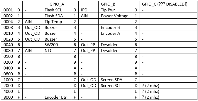
Some settings in the GPIO_C port apparently remained garbage from old versions / prototypes. The wiring has changed, the port has been turned off altogether, but for some reason the speed is changing.
IPU - push supply (default, unless otherwise specified)
IPD - push ground
AIN - analog in
Out_OD - Out Open-drain
Out_PP - Out Push-pull
frequency 50mhz (default unless otherwise indicated)
Some settings in the GPIO_C port apparently remained garbage from old versions / prototypes. The wiring has changed, the port has been turned off altogether, but for some reason the speed is changing.
Pay attention to the connection of the EEPROM Flash. I2C lines are wound up where there is no I2C hardware. A strange decision, isn't it?
Well, so much the better. I have never worked with I2C. And then there was such an opportunity to touch him at the level of manual control of the signals on the legs of the MK! I downloaded the dock from the TI website, drew a state table, sketched the code for the robot. So that he can decode the transmission according to the changes of the pins.
And then I was waiting for a bummer. EEPROM does not stop the debugger. And although theoretically she could have waited for the master, in practice everything falls apart completely.
Ok, knowing the operation of the protocol, we give the names to the functions, going up level by level to a bunch of Flash_ReadData / Flash_WriteData functions that differ little from each other (copy-paste?)
I look at the links - reading and writing is called from the place where the code is entered. Interesting! It turns out 4 byte response code after input is written in flash. And then read from there. Waiting for these operations I took for checking. And two different messages in Chinese - if they read the same as they did and if not (hardware error?).
It turns out that after entering the code is not checked. It is always checked at the start of the station. And if the verification fails, instead of the main RTOS task of the soldering iron, another RTOS task is created, which deals with entering the code and writing it to the flash. Well, it is logical.
In addition, read-write of a solid piece of data occurs in the adjacent flash functions. Size 0x3AE bytes. It looks like the settings. After reading them, the function of calculating the code from the buffer with data is called. Before the dental gnash resembles the function of calculating the ID1 and ID2. And even the data table is another one, exactly the same. Why use this code to check the integrity of the settings? Would take a better CRC! Wait, what if ...? I push the constants from the table into Google - exactly. This is the CRC. More precisely CRC16_CCIT. Two copies of the same function. Two copies of the tables. To the enemy did not guess.
Last steps
So, we control reading from a flash. "Reset init". The breakpoint quickly leads us to the place where the newly recorded response is read. We put a watchpoint on the read data. “Resume” The station shows the code entry interface as if nothing had happened.
DMA again? We look at the log. Immediately after copying the read code from the flash, two blocks of 32 bytes are copied. We look disassembler at the return address from the DMA operation. In the code we see after copying 32 bytes a call to a strange function with a bunch of xor inside. Put a breakpoint.
When calling a function, we see a buffer with some data, in the last 4 bytes of which the already familiar ID1 and ID2 stations lie. At the exit of the function we see a 16 bit number. Another call is a buffer with other data, at the end ID1 and ID2 are also located.
Curious information: the data in each of the 32-byte buffers are images of the corresponding hieroglyph. The last 4 bytes of the image are replaced in the buffer with ID1 + ID2. What are these hieroglyphs? Maybe the name of the developer? I do not know, I'm not strong in Chinese.And what if the result of the function is the desired code response? We start the station, enter the numbers obtained in the debugger, restart - and the code is accepted!
It remains to understand exactly what this mysterious function calculates. And she does this:
- a bunch of XOR between explicitly defined constants. Just took the final value. Let's call it “manyXorValue”.
- computes CRC16_CCIT from the beginning of itself. We also take the already calculated value. Let's call it "xorCodeCrc16".
- It considers CRC16, assuming the result as the initial value (manyXorValue xor xorCodeCrc16), and instead of the already familiar two copies of the CRC16 table, another table. Very similar, but still different.
It seems that the original table was cut into pieces of 8 elements, mixed, and glued together again. For example, the first piece was 0th. The 5th has not gone away. And on the 4th place is now the 31st. We write a short code for comparison, and here are the necessary permutations for assembling this strange table: 1, 2, 3, 4, 31, 5, 6, 7, 8, 9, 10, 11, 12, 0, 13, 25, 14, 15, 16, 17, 18, 19, 20, 21, 22, 23, 24, 26, 27, 28, 29, 30.
Rewritable in Python. Check - works. For debugging, I asked a few guys from the Internet, having the same stations, to give me their ID and check the generated RGs. Checked for another 5 stations. The result is correct.
Conclusion
- The basis of protection turned out to be an intricate and complex code of large volume (it did not count precisely, but at a rate of 10-15%), heavily mixed in with work with iron. I would not be surprised if RTOS multithreading also plays an important role. Fortunately, I was not going to understand all the subtleties of implementation.
- The station has earned with a newer firmware. Finally I assembled a chic aluminum handle with Tao for her. Soldered the same station.
UPDATE: In the comments already asked twice about this pen. Here is a great overview on it. - I learned a lot of new information about ARM Cortex M3 and STM32 peripherals.
- Frankly disappointed with the quality of the Chinese firmware. I will do an open, rewritten from scratch.
And if protection would be simpler? Probably would have entered the code, and forgot about it ...
Write in the comments if you are interested in finding out the continuation of the story: the reverse of the algorithms of the soldering station and the development of my version.
PS: Specially for this article rewrote the key generation code in javascript. Online version , there is also a link to the Python version. If the explanations were somewhere incomprehensible - you can learn the details from the code. And, of course, to revive your own station, blocked by updating or repairing iron.
Source: https://habr.com/ru/post/350602/
All Articles