Implement fast 2D shadows in Unity using 1D shadow mapping
Introduction
Recently, I started to implement a system of 2D shadows in Unity, which could be used in a real game. As known to professional developers, there is a big difference between what can be achieved in a technical demo and what is applicable for integration into a full game, where the implemented opportunity is just one of many. The effects on the CPU, video processor and memory must be in balance with everything else in the game. In practice, different projects have different limitations, but I decided to create a system that takes no more than a couple of milliseconds of processing time and no more than a few megabytes in memory.
With this restriction, I threw away the many already existing methods for calculating the shadows that I was able to find. Popular was a pair of techniques. In one, ray tracing implemented on the CPU was used, defining the boundaries of the silhouettes of the light-blocking geometry. In the other, all the obstacles to light were rendered into texture, and then a ray-stepping algorithm with several passes for creating a shadow map was performed for it. These techniques are usually used with no more than a pair of light sources and would definitely not allow me to work with dozens of light sources in accordance with the restrictions I have chosen.
Shadow overlay
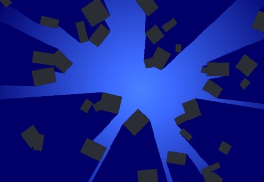
Therefore, I decided to create a 2D analogue of the method for calculating shadows, which is used in most modern 3D games: rendering geometry from the point of view of the source of illumination and creating a depth buffer that will allow us to determine if each pixel is rendered from the light source. This technique is called shadow mapping. In 3D, it creates a two-dimensional texture, that is, in 2D it will create a one-dimensional texture. The screenshot below shows my finished lighting map in the Unity resource view mode; but in fact it is not for one light source, but for 64: each row of pixels in the texture is a shadow map for a separate source.

This method uses polar coordinates to convert a 2D position into an angle and a distance (or depth) relative to another object.
')
inline float2 CartesianToPolar(float2 point, float2 origin) { float2 d = point - origin; // x - , y - return float2(atan2(dy, dx), length(d)); } That is, each line in the shadow map is 360 degrees around the light source, and each pixel represents the distance from the light source to the nearest opaque geometry in this direction. The greater the horizontal resolution of the texture, the greater the accuracy of the resulting shadows.
Opaque geometry, casting shadows, which I will call blocking geometry , is transmitted as a list of lines. Each pair of vertices creates a pair of positions in the polar space, after which the pixel shader fills the corresponding segment in the lighting map. Due to the use of the standard z-buffer test, only a pixel closest to the geometry is saved in each pixel. It would be wrong to simply interpolate the polar depth in the pixel shader to get the z-coordinate, because this is how we get curved shadows for straight edges. Instead, we need to calculate the intersection point between the line segment and the light beam at the current angle, but this is a matter of the entire pair of scalar products and division, which is not very expensive for modern video processors.
Difficulties
All this would be very simple if it were not for one spoon of tar - a serious problem when using polar coordinates arises when we get a straight line segment in polar coordinates, which is located on both sides of the border of 360 degrees. The usual solution would be to split a straight line into two separate parts: the first part would end at 360 degrees, and the other (the rest of the segment) would start at 0. However, the vertex shader gets only one vertex and produces one result, and there is no way to output two separate cut off. The main difficulty of this approach is to solve this problem.
You can solve it this way: present the original lines of the shadow map not in 360 degrees, but add an additional 180 degrees, that is, from 0 to 540. A straight line segment in the polar space takes no more than 180 degrees, therefore it is enough to accommodate any segment that is next to with a point of 360. This means that each line segment still creates one line segment at the output for the pixel shader, as it should.
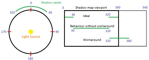
The disadvantage of this method is. that the first part of the line (from 0 to 180) and the last part (from 360 to 540) are actually one area in the polar space. To check the pixel against the shadow map, we need to determine whether the polar angle falls into this area, and if so, then take samples from two places and select at least two depths. This is not exactly what I wanted - branching and additional sampling will have a terrible effect on performance, especially in multiple texture sampling for Percentage Closest Filtering (PCF) (this technique is widely used to create smooth shadows based on shadow maps). My solution (after filling in all the lines of the shadow maps) is the following: performing another video processor pass through the shadow map, resampling it and combining the first 180 degrees with the last 180 degrees. By the usual frame buffer standards, the texture of the shadow maps is very small, so it takes a very short video processor time. As a result, we get a ready-made texture of the shadow map, in which one sample is enough to determine if the current pixel is lit by a specific light source.
The main disadvantage of this system is that for the recognition and processing of boundary cases the blocking geometry must have a special format. Each vertex of each line segment itself is similar to a line segment, because it stores the position of the other end of the line segment. This means that we have to either build the geometry in this format during the execution of the application, or in advance. We cannot simply transfer the geometry that is used for rendering. However, this has a good side: after building this special geometry, we at least do not transfer any unnecessary data, that is, the efficiency is higher.
Another great feature of this system is that the finished shadow map can be written back to the video processor, and this allows you to perform visibility requests through the CPU without the need for ray tracing. Copying the texture back to the video processor can be quite a costly task, and despite the fact that in Unity 2018 we are waiting for the long-awaited implementation of the asynchronous gpu read-backs video processor, this function should not be used without real need.
Algorithm
In fact, the algorithm works as follows.
- Create a mesh of line segments for shadow-casting geometry. If the geometry does not change, then you do not need to rebuild it in each frame. You can also use two meshes — one for static geometry and one for dynamic, to avoid unnecessary rebuilding.
- Render this blocking geometry for each shadow casting light source. In the demo, separate draw calls are used for this, but this is a great opportunity to use duplication (instancing), so that the mesh is transferred to the video processor only once. Each light source is assigned a string in the shadow map, and this data is transmitted to the shader through shader constants, which allows you to create a suitable Y coordinate to which you want to write.
- In the vertex shader, straight line segments are transformed into polar space.
- The video processor shadows the straight lines in the current line of the shadow texture, performing a z-test to store only the nearest pixels.
- Resampling the finished shadow map into another texture to eliminate the parts related to the same polar region.
- For each light source, we render a quadrilateral covering the maximum range of the source (for example, the radius of a point light source). For each pixel, we calculate the polar coordinate in accordance with the light source, and use it to sample the shadow map. If the polar distance is greater than the value read from the shadow map, then the pixel is not illuminated by the light source, that is, the light is not applied to it.
And here are the finished results. For the stress test, I set 64 moving shadow-casting point light sources with random-sized lighting cones, moving between several rotating opaque objects.

What were the costs? If we assume that the blocking geometry is static, and that we use geometry duplication (instancing), then a complete shadow map for any number of sources (subject to texture size restrictions) can be transferred to the video processor for a single draw call. The amount of redrawing in the shadow map is determined by the complexity of the illumination-blocking geometry, but since the texture is very small compared to modern frame buffers, the performance of the video processor cache should be fantastic. Similarly, when we get to the shadow map sampling, it does not differ from the shadow mapping in 3D, except that the shadow map will be much smaller.
Our game consists of a single large environment and we have 64 constantly active and shadow-casting sources of lighting, so I used the texture of a shadow map with a size of 1024x64. Costs within the general budget of frame computing turned out to be minimal.
Additional features
If you want to expand this system, then I can offer a couple of interesting possibilities. When processing a shadow map to eliminate two overlapping areas, you can use the opportunity and convert the values to create an exponential shadow map, and then blur it (do not forget that you only need to blur in the horizontal direction, otherwise it will affect sources unrelated to each other! ). This will allow us to create smooth shadows without multisampling the shadow map. Second, as I mentioned earlier, the demo now performs a separate draw call to transfer the shading geometry of each source, but if you pack the position of the light source and other parameters into the matrix, you can trivially do this in a single draw call using duplication (instancing).
Moreover, I believe that with almost no additional work on the part of the CPU, radiosity lighting with a single reflection can be used as an extension of the system. To do this, you can use the following principle: the video processor can use the shadow map from the past frame to calculate reflections of the rays of light in the scene. So far I can not say anything more detailed, because I have not yet implemented this system. If it works, it will be much more efficient than regular implementations of Virtual Point Light, which use ray tracing performed by the CPU.
In addition, you can use this system in many interesting ways. For example, if you replace sources of illumination with sound emitters, then this system can be used to calculate sound absorption. Or it can be used to determine the field of view in AI procedures. In general, it is possible to turn the ray tracing into a texture search.
Completion
This concludes the story of the implementation details of my one-dimensional shadow overlay system. If you have any questions, ask them in the comments to the original article .
Source code demo
https://www.double11.com/misc/uploads/1DShadowMapDemo.zip
Source: https://habr.com/ru/post/350396/
All Articles