Micro course on programming SCADAPack controllers in C
On Habré, there are frankly few articles about automated process control systems. Moreover, I suspect that programming in the industry of industrial automation for the majority of habrovchan is a kind of magical dark forest with strange legends and creatures. And here I wanted to conduct a small tour of this forest for educational purposes, but we will not be limited to educational purposes, and we will try to make this material useful for people just starting their way in an automated process control system, or having first encountered the type of controllers in question.
')
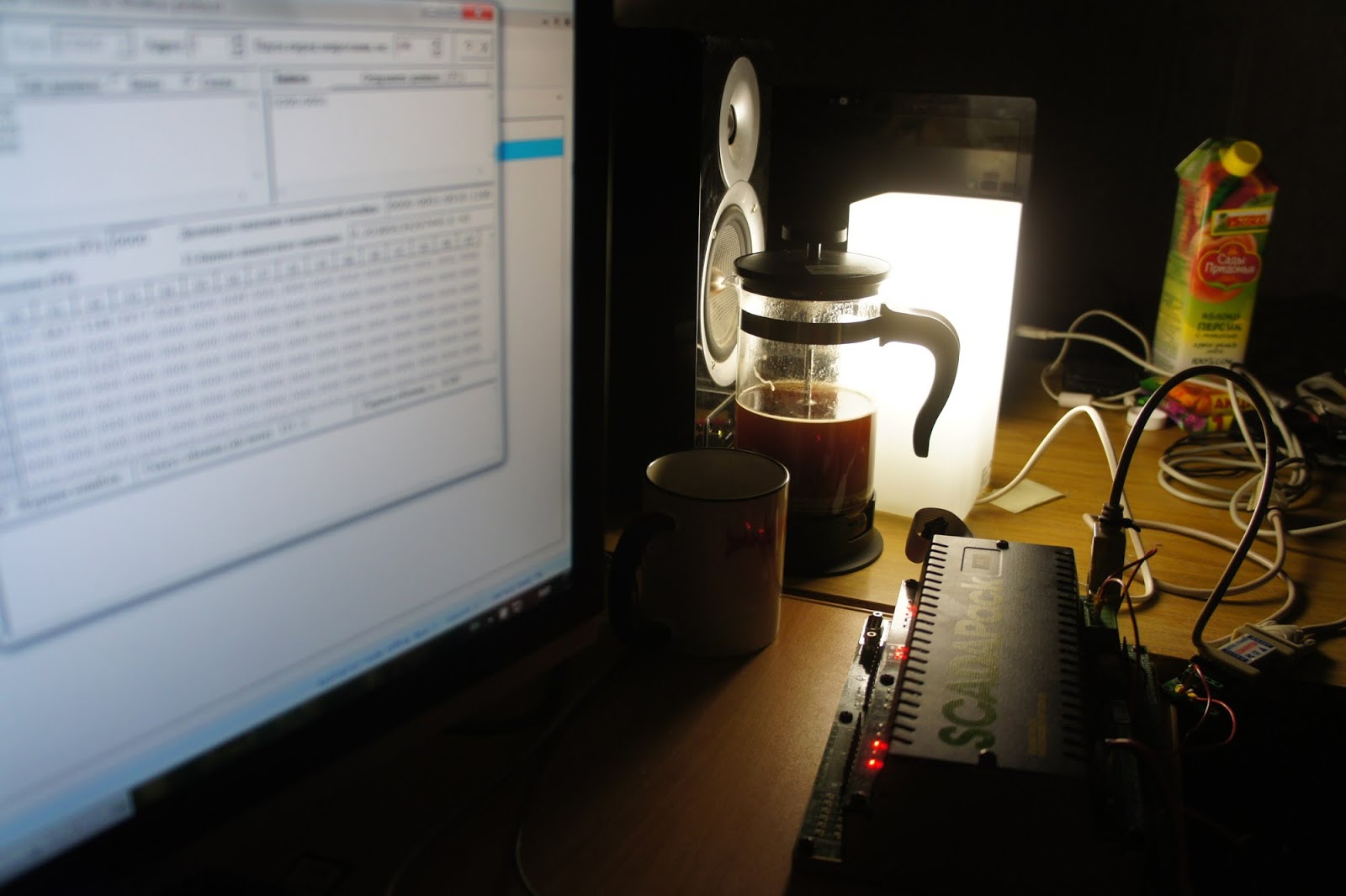
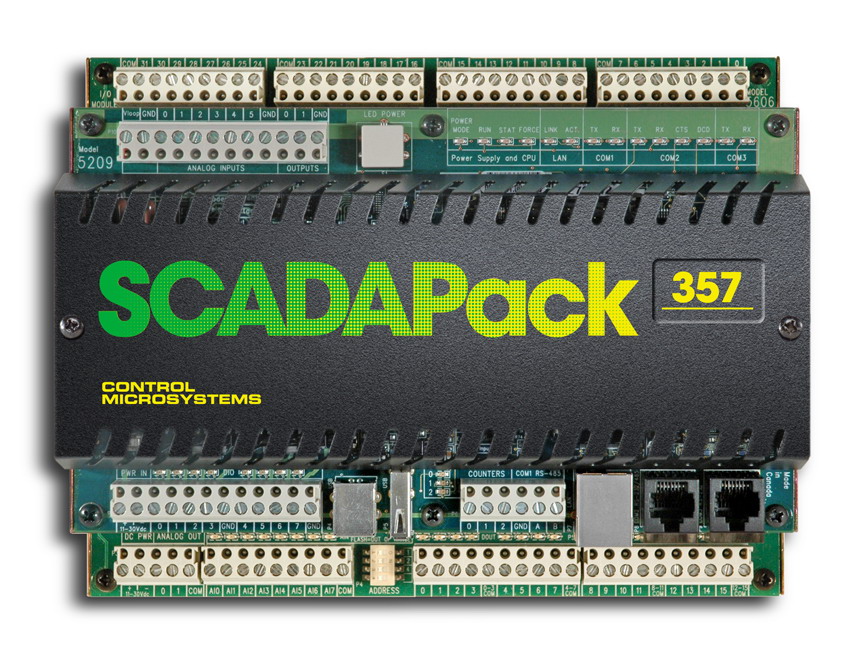
So, get acquainted. This is a programmable logic controller (PLC) called SCADAPack by Schneider Electric (formerly Control Microsystems).
Programmable logic controller (abbr. PLC; English programmable logic controller, abbr. PLC; more accurate translation into Russian - controller with programmable logic), programmable controller - an industrial controller used to automate technological processes. The main mode of operation of the PLC is its long-term autonomous use, often in adverse environmental conditions, without serious maintenance and with little or no human intervention. [Wikipedia]
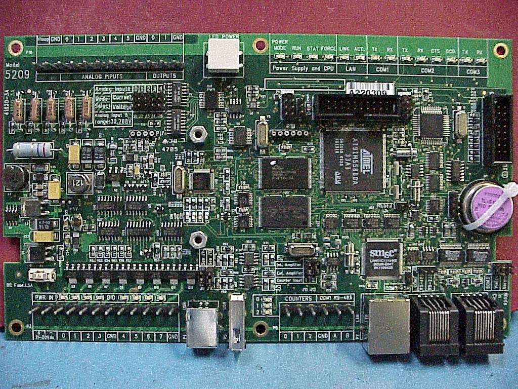
These PLCs have earned fame for their reliability and rich programming possibilities. Inside the controller, depending on the series, there is an ARM processor running the VxWorks operating system.
In industrial automation, the generally accepted standard is the languages of IEC, such as LD / LAD, FDB and ST. The first of them is nothing more than schemes similar to ladder logic circuits. The second is nothing more than circuits that are similar to circuits with logic elements and electronic components (timers, counters, etc.). The third is a textual language, evoking memories of Pascal. But today we will not talk about them (anyone can always google it), but about developing for these controllers in C, which is, firstly, much closer to “simple programmers”, and secondly, it saves if necessary to program complex mathematical calculations or implement non-standard communication protocols .
To compile, we will need a compiler, header files, and a standard controller library. All this can be found on the manufacturer's website under the name C Tools , and the description of the API is there.
Development begins with writing a Makefile (a script to build a project from source to a binary file). An example makefile can be found in the C Tools directory:
C:\Program Files\Control Microsystems\CTools\Controller\Framework Applications\TelePACEThere is also an example of main.cpp and the appstart.cpp file (it is also required for assembly).
Ctools.h C:\Program Files\Control Microsystems\CTools\Controller\TelePACEPay attention to it stands on 3 things:
objects = appstart.o main.oThis line specifies which files to compile to build the firmware. If your project is divided (as it should be) into .c- or .cpp-files with headers (.h- or .hpp-files), then they should be listed in this section. If you forget something, the compiler will remind you of the Undefined reference error.
CTOOLS_PATH = C:\Program Files\Control Microsystems\CToolsThis is the way to ctools. Score if you have it different.
TARGET = SCADAPack350This line defines for which family of controllers we compile the firmware. Possible options:
SCADAPack350 ( 357, ..), SCADAPack33x, 4203The firmware is
make using the command line command make .If a message is displayed that you could not find this command, check that the path to the C-Tools libraries is registered in your PATH system variable:
C:\Program Files\Control Microsystems\CTools\Arm7\host\x86-win32\binSimple application
To compile a simple (and empty) firmware, we will need a
Makefile , the appstart.cpp and main.cpp files.Their examples can be found in the same C Tools directory that was mentioned above. Appstart.cpp is responsible for initializing the hardware and the runtime, and in main.cpp we can write the code we need.
The general structure of the C program for SP looks like this:
#include <ctools.h> #include "nvMemory.h" int main(void) { // - , , , , .. while (TRUE) { // release_processor(); } } The call to release_processor () is necessary in each cycle, because in addition to our program, the controller's OS also performs other utility processes (port and protocol handlers, runtime, etc.). Without calling this function, for example, after starting the program it will be impossible to stop it or reflash the controller.
C Tools’s coding style, alas, leaves much to be desired: there are different styles of function naming (process_io () and release_processor (), but ioReadDin16 () and addRegAssignment (), and also getclock () / setclock ()), in some similar functions with the same arguments, these very arguments are reversed; in short, be careful.
From the general tips for developing reliable embedded systems: try to write as simple and clear code as possible, stick to the chosen coding standard, be careful with type conversions, better avoid dynamic memory allocation and pointer arithmetic without much need.
As a basis for the rules, you can take the individual items of the MISRA standards (development standard for embedded software for cars) or JSF (for aviation).
Download the program to the controller
For this we need TelePACE. It is possible to connect to the controller via RS232 / 485, via Ethernet and even via USB (if the used scadapack model has it).
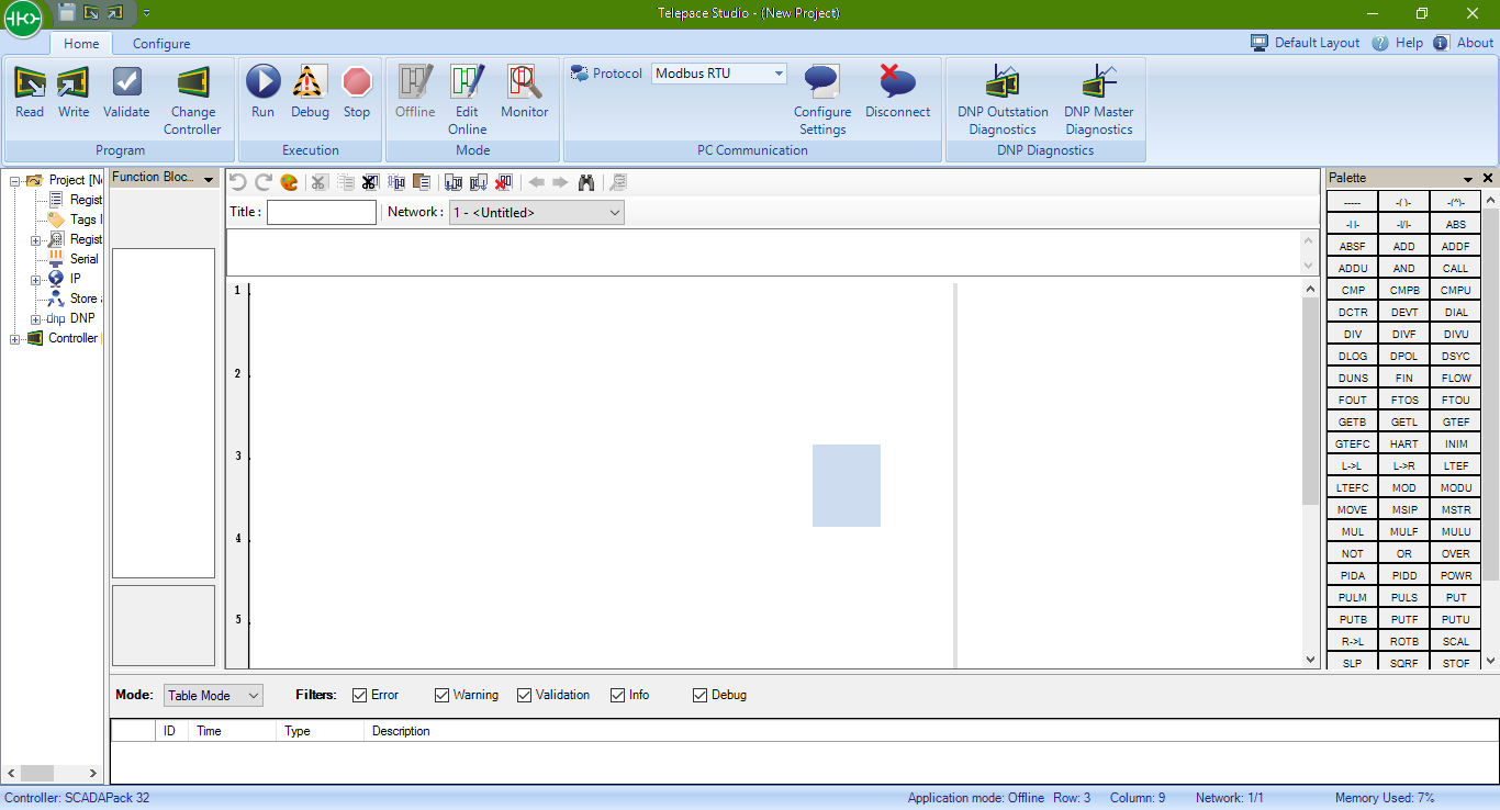
The principle is about the same:
- Select the desired protocol in the Protocol field (Modbus RTU, Modbus TCP or Modbus USB)
- Click Configure Settings and set all the necessary data (RTU address, port speed for RS232 / 485 or IP address for TCP)
- Click Connect and make sure that you are connected to the controller.
- On the Initialize tab, you can reset the controller to its original appearance — delete all programs, LAD projects, port settings, and register assignments.
- On the C / C ++ tab, you can see how the program is loaded into the controller, stop / start it, load a new one (examine the buttons at the top of the tab!).
On the web, there was a very helpful video showing the process:
Work with timers
Let's start with the simplest program - Hello World, namely, we blink the LED on the controller :)
#include <ctools.h> #include "nvMemory.h" // ID . 10, primitiv.h #define TIMER1EVENT 10 int main(void) { int led_state = 0; // , 1 1 ( 0.1 ) startTimedEvent(TIMER1EVENT,10); while (TRUE) { // , if (poll_event(TIMER1EVENT)) { if (led_state == 0) ledPower(LED_ON); else ledPower(LED_OFF); led_state = led_state ^ 1; } release_processor(); } } Working with modbus registers
Modbus is an open communication protocol based on the master-slave architecture. It is widely used in industry for organizing communication between electronic devices. It can be used for data transmission through serial communication lines RS-485, RS-422, RS-232, and TCP / IP networks (Modbus TCP). There are also non-standard implementations using UDP. The main advantages of the standard are openness and mass character. The industry now produces a lot of types and models of sensors, actuators, modules for processing and normalizing signals, etc. Almost all industrial control and management systems have software drivers for working with MODBUS networks. [Wikipedia]
In SCADAPack, working with Modbus is implemented beautifully and conveniently.
The modbus registers memory of the controller is non-volatile, and is not lost even after a reboot or power failure. On the one hand, this is a bit inconvenient (do not forget to clear or initialize the registers at the start, if necessary), but on the other hand, it allows you to store settings, setpoints, and even small archives in the address space of the modbus.
In addition, the results of the execution of various commands (reading the status of discrete and analog inputs, polling external devices, etc.) are placed in the modbus registers.
The modbus handler in the skadapas is implemented at the operating system level, and therefore after starting the program, on all COM ports (and on Ethernet) we can immediately interrogate the controller on the modbass (we will discuss port configuration later). Moreover, the controller will respond to modbus requests even if the program is stopped.
Writing and reading modbus registers is performed by dbase () and setdbase () functions, for example, like this:
request_resource(IO_SYSTEM); a = dbase(MODBUS, 30001); b = dbase(MODBUS, 30002); setdbase(MODBUS, 40020, a * b); release_resource(IO_SYSTEM); This example reads two numbers from the registers 0001 and 0002 of the Inputs zone and stores the result of their multiplication in register 0020 of the Holding zone. It's simple.
Work with I / O signals
Work modules input and output can take place in three ways:
First way
The first option is to create a “register assignment”. The state (discrete and analog values) of the input channels of the DIN and AIN modules will be automatically “displayed” in the modbus registers, and vice versa, for the DOUT and AOUT modules, the state of the outputs will be determined by the values recorded in the registers. To do this, use the clearRegAssignmnet (clear all old assignments) and addRegAssignment (create new) functions.
The first function addRegAssignment is the module type (a list of constants can be found in the TelePACE documentation and in the header files, can be DIN_5401, DIN_5404, AIN_5301 and others), the second is the module address (it is usually set with a jumper on the module itself, and if built-in SP inputs, then 0), and then go the addresses of registers, starting with which the recording should be made (if the module provides data of different types, then there will be several groups of registers - coils, status, inputs, etc.)
// IO_SYSTEM // - modbus- request_resource(IO_SYSTEM); // assignments clearRegAssignment(); // IO 5601 10001 30001 // DOUT 1 (00001) addRegAssignment(SCADAPack_lowerIO, 0, 1, 10001, 30001, 0); // , SCADAPack_upperIO - ( ) // 5604: // , AOUT, 40001 // addRegAssignment(SCADAPack_5604IO, 0, 1, 10001, 30001, 40001 ); // AOUT ( 1): // , modbus 40001 addRegAssignment(SCADAPack_AOUT, 1, 40001, 0, 0, 0); // IO_SYSTEM release_resource(IO_SYSTEM); It should be borne in mind that if you forcefully stop the runtime environment (runTarget (FALSE)), they will not work, but if you did not make changes to the standard appstart.c file for optimization purposes, then there is nothing to worry about.
Do not forget to perform clearRegAssignment (); when you start the program, even if you do not use them - who knows who did what on this controller to you.
If you don’t know exactly which I / O board will be on the controller where your firmware will be running, you can use the solution proposed by the experts from OZNA .
Second way
Call explicitly read functions that store data in the specified modbus registers.
These can be functions ioRead8Din, ioRead8Ain, ioRead16Din, ioRead16Ain, ioRead5604Inputs, ioWrite16Dout, ioWrite5604Outputs, ioRead4Counter (for counting inputs), ioReadSP2 (for embedded inputs, for example, for read inputs, ioRead4Counter (for counting inputs), ioReadSP2 (for built-in inputs, for example, for read inputs, for ioRead4Counter, for counting inputs), ioReadSP2 (for embedded inputs, for example inputs, for learning inputs, for learning inputs, for learning inputs for learning inputs for learning inputs, for learning) Details and syntax of these commands can be found in the documentation for C Tools, usually the first argument is the module address (0 for embedded inputs), and the second and further are modbus register addresses from which the values of the signals should be saved (or where they should be taken for recording on weekends).
Example:
// 5607 (0, .. ) int Module5607Addr = 0; // IO_SYSTEM request_resource(IO_SYSTEM); // ioRequest(MT_5607Inputs, Module5607Addr); ioRequest(MT_SP2Inputs, 0); // // , ( wait_event poll_event) ioNotification(IO_COMPLETE); wait_event(IO_COMPLETE); // 5607, – 10001, – 30001 ioRead5607Inputs(Module5607Addr, 10001, 30001); // , – 10101, – 30101 ioReadSP2Inputs(10101,30101); // IO_SYSTEM release_resource(IO_SYSTEM); Calling ioWrite * functions will similarly set the required values from modbus registers to the output channels of the controller and modules.
Third way
The same, but with the preservation of the results not in the modbus registers, but in variables or an array. Functions are called the same, but have an overloaded implementation with different arguments.
int Module5607Addr = 0; // IO_SYSTEM, - request_resource(IO_SYSTEM); // , 5607 UCHAR DIData [3]; // , 5607 INT16 AIData [8]; // UCHAR DIData2 [2]; // INT16 AIData2 [8]; // ioRequest(MT_5607Inputs, Module5607Addr); ioRequest(MT_SP2Inputs, 0); // // , ( wait_event poll_event) ioNotification(IO_COMPLETE); wait_event(IO_COMPLETE); // ioRead5607Inputs(Module5607Addr,DIData,AIData); ioReadSP2Inputs(DIData2,AIData2); release_resource(IO_SYSTEM); Something similar can be done with the data we want to write to the output channels (for example, to close the relay output):
UINT16 InputType[8]; for(int i=0;i < 8; i++) InputType[i] = 3; UINT16 InputFilter = 3; UINT16 ScanFrequency = 0; UINT16 OutputType = 1; UINT16 Mask2 = 0; ioWrite5607Outputs(Module5607Addr,DOData,AOData,InputType,InputFilter,ScanFrequency,OutputType); ioRequest(MT_5607Outputs, Module5607Addr); Specific functions and constants for reading and writing data to the modules used must be viewed in the documentation and in the C Tools header files. For example, the functions for the 5607 module, as you can see above, have additional options for setting the input type, filter parameters, etc. They are also described in the documentation.
There are also functions for obtaining the current temperature of the controller and battery voltage - readThermistor (T_CELSIUS), readBattery (). Trifle, but useful.
AI scaling
The analog input channels of the controller modules can operate in different modes (for example, with input ranges of 0–20 or 4–20 mA, this is determined by jumpers on the module). They give out the data in ADC units, and converting them to the scale we need (for example, 4-20 mA will correspond to 0-100%) is quite simple:
// , AI, #define AIWaterLevelReg 30001 float WaterLevelScaled = ((float)dbase(MODBUS, AIWaterLevelReg) - 6554) / 26214 * 100; // 4-20 // float WaterLevelScaled = (float)dbase(MODBUS, AIWaterLevelReg) / 32767 * 100; // 0-20 Naturally, instead of 100 you can multiply the number by the upper limit of the scale you need.
Configuring RS-232 / RS-485 Ports
Here, again, no magic:
PROTOCOL_SETTINGS comsettings; pconfig portSettings; // COM2, getProtocolSettings(com2, &comsettings); // modbus-, comsettings.station = 1; comsettings.type = MODBUS_RTU; comsettings.mode = AM_standard; get_port(com2,&portSettings); // , 38400 portSettings.baud = BAUD38400; portSettings.duplex = HALF; portSettings.parity = PARITY_NONE; portSettings.data_bits = DATA8; portSettings.stop_bits = STOP1; portSettings.flow_tx = TFC_NONE; portSettings.flow_rx = RFC_MODBUS_RTU; portSettings.type = RS232; setProtocolSettings(com2, &comsettings); set_port(com2,&portSettings); Port settings are saved in the EEPROM, however, depending on the controller configuration, library versions, etc., it is possible to read, for example, from the same modbus registers to a specific event (command, jumper closure, etc.) to automatically reconfigure and update them.
Modbus Device Polling
If you want not only to work as a slave device, but also to poll other controllers or sensors yourself, there are functions of the master_message () type that allow you to poll external devices on the modbase, and save the results to your registers, from where they can be read and used in the algorithm (or just provide the top level). There are examples in the documentation, just consider two nuances: you must check the result of the function execution with the command get_protocol_status () before sending a second request or working with the received data, and the second thing: you must either disable the modbus handler on the port you are using, or monitor so that its address does not coincide with the address of the polled device (otherwise you can get undefined behavior or strange errors).
extern unsigned master_message(FILE * stream, unsigned function, unsigned slave_station, unsigned slave_address, unsigned master_address, unsigned length); stream - the port through which data will be exchanged (for example, com1), function is the modbus function number for the request (for example, 3), slave_station is the RTU address of the polled device, slave_address is the starting address of the registers in the remote device that we want to read, master_address - the starting address of the registers on our controller, where the data will be written, length - the number of registers to read).
Example:
request_resource(IO_SYSTEM); // com2 3- modbus- ( Holding ) 1 0001 (40001) 17 , 513 master_message(com2, 3, 1, 40001, 40513, 17); // struct prot_status polling_status; polling_status = get_protocol_status( com2); if (polling_status.command == MM_SENT) { // , . // , , } else if (polling_status.command == MM_RECEIVED) { // , ! // } else { // - . } release_resource(IO_SYSTEM); You can also install your Modbus handler (installModbusHandler ()) to implement any protocol extensions.
The system keeps statistics of the exchange (accepted / sent, number of errors, etc.), which can also be read from the relevant structures.
Communications
You can also install your own data handler that came through COM ports (install_handle ()) to implement some non-standard protocols.
TCP / IP is fine too. Standard BSD Sockets functions are available: bind (), getsockopt (), etc. Network settings on the controller can be programmatically read and written (ethernetGetIP (), ethernetSetIP ()).
Maintaining archives
SCADAPack DataLog C Tools, , , , , . , , Holding Inputs ( , ) , .
, POSIX-, ( USB Flash-), , .
-:
FILE *mdata; char* file_mdata = "/d0/logs.dat"; mdata = fopen(file_mdata, "w"); fputs("test log string", mdata); fclose(mdata); ( — ) , modbus-, () modbus- .
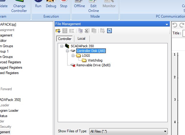
/d0/ , /bd0/ — USB- . , , .
TelePACE , .
As I have already noted, in the non-volatile memory, first of all, the data of the Modbus registers are stored, that is, the values stored in them will be available even after the controller is rebooted.
, s_nvMemory, nvMemory.h, 8 , ( ) , . , allocateMemory() 1 , , .. — s_nvMemory, , , (freeMemory()). DYNAMIC_MEMORY.
, ( createTask(), getTaskInfo() ..), ( 'envelopes').
Multitasking is cooperative, that is, switching between tasks and programs is not performed by the operating system, but alternately when they themselves are ready to transfer the execution further or when certain events occur. On the one hand, this solves the problem of the atomicity of operations when sharing data, and on the other hand, one should not forget to call release_processor () and not to seize resources for too long. An example of a multitasking program and state change graphs when events occur are described in the documentation in the chapters "RTOS Example Application Program" and "Explanation of Task Execution".
Dynamic memory
malloc() free() , new delete. — (, Stop), : (installExitHandler) .
.
getclock setclock, .
, - 5604, AI 2 , DO1 .
( SCADA HMI), , , .
0020 Holding (40020) SCADA HMI-.
«» , .
COM2.
#include <ctools.h> #include "nvMemory.h" /** * @brief 5604 modbus- */ void initialize_io() { request_resource(IO_SYSTEM); clearRegAssignment(); addRegAssignment(SCADAPack_5604IO, 0, 1, 10001, 30001, 40001); release_resource(IO_SYSTEM); } /** * @brief COM2 Modbus Slave, = 1, = 9600 */ void initialize_ports() { request_resource(IO_SYSTEM); PROTOCOL_SETTINGS comsettings; pconfig portSettings; getProtocolSettings(com2, &comsettings); comsettings.station = 1; comsettings.type = MODBUS_RTU; comsettings.mode = AM_standard; get_port(com2,&portSettings); portSettings.baud = BAUD9600; portSettings.duplex = HALF; portSettings.parity = PARITY_NONE; portSettings.data_bits = DATA8; portSettings.stop_bits = STOP1; portSettings.flow_tx = TFC_NONE; portSettings.flow_rx = RFC_MODBUS_RTU; portSettings.type = RS232; setProtocolSettings(com2, &comsettings); set_port(com2,&portSettings); request_resource(IO_SYSTEM); } /** * @brief AI- * @param ai_value "" AI * @param max AI ( ) * @return */ float scale_ain(int ai_value, float max) { return ((float)ai_value - 6554) / 26214 * max; } /* . #include */ #define AILevelReg 30002 // , AI (2- AI) #define LevelScaledReg 40020 // , #define PumpLevelTriggerReg 40050 // , SCADA ( ) #define PumpOutReg 1 // DO, (1- DO) #define LevelHyst 50 // . , #define MaxLevelMeters 500 // ( ), int main(void) { // COM initialize_ports(); // - initialize_io(); while (TRUE) { request_resource(IO_SYSTEM); // AI , int level_raw = dbase(MODBUS, AILevelReg); float level_scaled = scale_ain(level_raw, MaxLevelMeters); setdbase(MODBUS, LevelScaledReg, (int)level_scaled); // , if (level_scaled > (dbase(MODBUS, PumpLevelTriggerReg) + LevelHyst)) setdbase(MODBUS, PumpOutReg, 1); else // - if (level_scaled < (dbase(MODBUS, PumpLevelTriggerReg) - LevelHyst)) setdbase(MODBUS, PumpOutReg, 0); release_resource(IO_SYSTEM); release_processor(); } } , ,
A description of all functions and examples of their use are in the documentation for C Tools.
It is very good to have complete knowledge of C (for example, when implementing algorithms, this concerns type conversion) in order to write code beautifully and without errors.
Learn, experiment, and succeed!
Many thanks to Denis for help in preparing the material and valuable comments :)
Source: https://habr.com/ru/post/350282/
All Articles