Learn OpenGL. Lesson 4.8 - Advanced GLSL

Advanced GLSL
This lesson will not show you new advanced tools that significantly improve the visual quality of the scene. In this lesson we will go through more or less interesting aspects of GLSL and touch on some pretty good moves that can help you in your aspirations. Basically, the knowledge and tools that make your life easier when creating OpenGL applications in conjunction with GLSL.
We will discuss some interesting built-in variables , new approaches in the organization of input-output shaders, and a very useful tool - the uniform-buffer object .
Content
Part 1. Start
Part 2. Basic lighting
')
Part 3. Loading 3D Models
Part 4. OpenGL advanced features
- Opengl
- Creating a window
- Hello window
- Hello triangle
- Shaders
- Textures
- Transformations
- Coordinate systems
- Camera
Part 2. Basic lighting
')
Part 3. Loading 3D Models
Part 4. OpenGL advanced features
GLSL embedded variables
Shaders are self-sufficient, if we need data from any other source, we will have to transfer them to the shader. We learned how to do this with vertex attributes, uniforms, and samplers. However, there are several other variables defined in GLSL with the prefix gl_ , which gives us additional opportunities to read and / or write data. We have already seen two representatives, the resulting vectors: the vertex shader gl_Position and the fragment shader gl_FragCoord .
We will discuss some of the interesting input and output variables that are embedded in GLSL, and explain how they are useful. I note that we will not discuss all the embedded variables in GLSL, so if you want to see all the embedded variables, you can do this on the corresponding OpenGL page .
Vertex Shader Variables
We have already worked with the variable gl_Position , which is the output vector of the vertex shader, defining the position vector in the clipping space. Setting the gl_Position value is a prerequisite for displaying something on the screen. Nothing new for us.
gl_PointSize
One of the processed primitives that we can choose is GL_POINTS . In this case, each vertex is a primitive and is treated as a point. You can also set the size of the points to be processed using the glPointSize function. But we can also change this value through a shader.
In the output float of the gl_PointSize variable declared in GLSL, you can set the height and width of dots in pixels. By describing the size of the point in the vertex shader, you can influence this value for each vertex.
By default, resizing a point in the vertex shader is disabled, but if you want, you can cast the Open_PL GL_PROGRAM_POINT_SIZE flag:
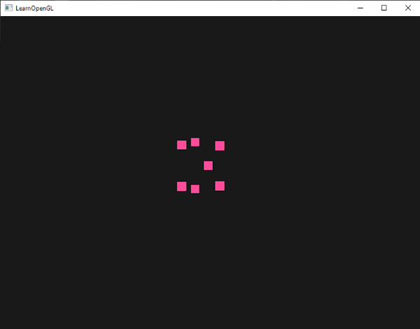
glEnable(GL_PROGRAM_POINT_SIZE); A simple example of resizing a point is to set the size of the point equal to the value of the z component of the clipping space, which, in turn, is equal to the distance from the vertex to the observer. The size of the point will increase, the further we are from the top.
void main() { gl_Position = projection * view * model * vec4(aPos, 1.0); gl_PointSize = gl_Position.z; } As a result, the farther we are from the points, the larger they are displayed.
Resizing a point for each vertex will be useful for such techniques as particle generation.
gl_VertexID
The variables gl_Position and gl_PointSize are output variables, since their values are read as output from the fragment shader stage, and by writing we can influence them. The vertex shader also provides the gl_VertexID input variable, from which only reads are possible.
The integer variable gl_VertexID contains the identifier of the vertex to be drawn. During the execution of the index render (using glDrawElements ), this variable contains the current index of the vertex to be drawn. During rendering without indices (via glDrawArrays ), the variable contains the number of vertices processed at the moment since the render call.
Although it is not very necessary now, knowing about the presence of such a variable is useful.
Fragment shader variables
Inside the fragment shader, we also have access to some curious variables. GLSL provides us with two input variables gl_FragCoord and gl_FrontFacing .
gl_FragCoord
We already saw gl_FragCoord a couple of times while we were discussing depth checking, because The z component of the gl_FragCoord vector is equal to the depth value of a particular fragment. However, we can also use x and y components for some effects.
The x and y components of the gl_FragCoord variable are the coordinates of a fragment in the window's coordinate system, originating from the lower left corner of the window. We specified the 800x600 window size using glViewport , so the fragment coordinates in the window coordinate system will be between 0-800 in x and a range of 0-600 in y.
Using the fragment shader, we can calculate various color values based on the screen coordinates of the fragment. The usual use of the gl_FragCoord variable is to compare the apparent result of the calculations of various fragments, as is usually done in technical demo versions. For example, we can divide the screen into two parts, rendering the part on the left half of the screen, and the other part - on the right half of the screen. Below is an example of a fragment shader that displays various colors based on screen coordinates.
void main() { if(gl_FragCoord.x < 400) FragColor = vec4(1.0, 0.0, 0.0, 1.0); else FragColor = vec4(0.0, 1.0, 0.0, 1.0); } Since the width of the window is 800, if the pixel coordinates are less than 400, it should be on the left side of the screen, and this gives us an object of a different color.
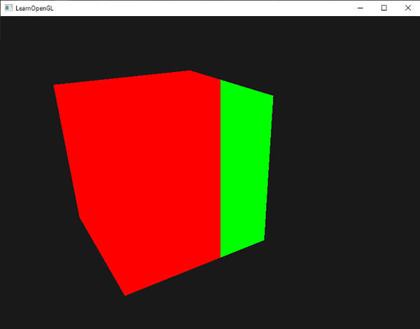
Now we can calculate two completely different results in the fragment shader and display each on its own part of the screen. This is great for testing various light mechanics.
gl_FrontFacing
Another interesting variable in the fragment shader is gl_FrontFacing . In the lesson, face cut - we mentioned that OpenGL can determine whether a face is a face in the order of traversing vertices. If we do not use face clipping (by activating the GL_FACE_CULL flag), then the gl_FrontFacing variable tells us whether the current fragment is a front or non-part. We can count different colors for the front part for example.
The boolean variable gl_FrontFacing is set to true if the fragment is on the front face, otherwise it is false . For example, we can create a cube with different textures inside and outside.
#version 330 core out vec4 FragColor; in vec2 TexCoords; uniform sampler2D frontTexture; uniform sampler2D backTexture; void main() { if(gl_FrontFacing) FragColor = texture(frontTexture, TexCoords); else FragColor = texture(backTexture, TexCoords); } If we look inside the container, we will see that a different texture is used there.
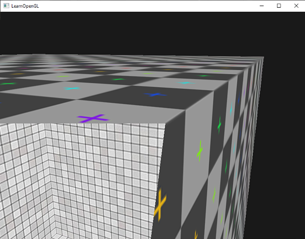
I note that if you activate face clipping, you will not see any faces within the container, so using gl_FronFacing will be useless.
gl_FragDepth
gl_FragCoord is an input variable that allows us to read the coordinates in the window coordinate system and get the value of the depth of the current fragment, but this variable is read only . We cannot change the coordinates of the fragment in the coordinate system of the window, but we can set the value of the depth of the fragment. GLSL provides us with the output variable, gl_FragDepth , using which we can set the value of the fragment depth inside the shader.
Setting the depth value is simple - you just need to write the float value from 0.0 to 1.0 in the variable gl_FragDepth .
gl_FragDepth = 0.0; // If the shader does not write the value to gl_FragDepth , then the value for this variable will be automatically taken from gl_FragCoord.z .
However, self-setting of the depth value has a significant drawback, since OpenGL disables all early depth checks (as discussed in the depth test ) as soon as the fragment shader has an entry in gl_FragDepth . This is done due to the fact that OpenGL cannot know what depth value the fragment will have before the fragment shader is launched, since a fragment shader could completely change this value.
Writing to gl_FragDepth , you should think about a possible drop in performance. However, starting with version 4.2 of OpenGL, we can find a compromise by redefining the gl_FragDepth variable at the beginning of the fragment shader with the depth condition .
layout (depth_<condition>) out float gl_FragDepth; The condition parameter can take the following values:
| Condition | Description |
|---|---|
| any | Default value. Early depth check disabled - you lose performance |
| greater | You can set the depth value only greater than gl_FragCoord.z |
| less | You can set the depth value only less than gl_FragCoord.z |
| unchanged | In gl_FragDepth, you write a value equal to gl_FragCoord.z |
In the example below, we increase the depth value in the fragment shader, but also want to keep the early depth check in the fragment shader.
#version 420 core // OpenGL out vec4 FragColor; layout (depth_greater) out float gl_FragDepth; void main() { FragColor = vec4(1.0); gl_FragDepth = gl_FragCoord.z + 0.1; } This property is only available in OpenGL 4.2 and higher.
Interface blocks
Until now, whenever we wanted to transfer data from a vertex shader to a fragment shader, we declared several corresponding input / output variables. This method is the easiest to transfer data from one shader to another. As applications become more complex, you may want to pass more than a few variables, which may include arrays and / or structures.
To help us organize variables GLSL provides such a thing as interface blocks , which allows you to group variables together. The declaration of such interface blocks is in many ways similar to the structure declaration, except for the use of the in and out keywords, based on the use of the block (input or output).
#version 330 core layout (location = 0) in vec3 aPos; layout (location = 1) in vec2 aTexCoords; uniform mat4 model; uniform mat4 view; uniform mat4 projection; out VS_OUT { vec2 TexCoords; } vs_out; void main() { gl_Position = projection * view * model * vec4(aPos, 1.0); vs_out.TexCoords = aTexCoords; } Here we declared the interface block vs_out , grouping all output variables together, which will be sent to the next shader. This is a trivial example, but just imagine how this can help you organize your I / O in shaders. This will also be useful in the next lesson on geometry shaders when you need to combine shader I / O into arrays.
Then we need to declare the input interface block in the next shader - the fragment one. The block name ( VS_OUT) should be the same, but the instance name ( vs_out , used in the vertex shader) can be any, the main thing to avoid confusion in the names (for example, calling the instance containing the input data vs_out ).
#version 330 core out vec4 FragColor; in VS_OUT { vec2 TexCoords; } fs_in; uniform sampler2D texture; void main() { FragColor = texture(texture, fs_in.TexCoords); } Since the names of the interface units are the same, their corresponding I / O is combined together. This is another useful feature that helps you organize your code and prove its usefulness when switching between specific stages like a geometric shader.
Uniform buffer
We have been using OpenGL for quite some time and have learned some good moves, but also received some inconveniences. For example, when we constantly use more than one shader, we have to set uniforms, while most of them are the same in each shader - why do we have to do it again?
OpenGL provides us with a tool called Uniform Buffer , which allows us to declare a set of global Uniform variables that remain the same in each shader. When using Uniform Buffer, we need to set the required Uniform variables only once . But we still have to take care of the unique variables for a particular shader. However, to configure the object uniform-buffer, we will have to sweat a little.
Since the uniform-buffer is a buffer, like any other buffer, we can create it through the function glGenBuffers , bind it to the target GL_UNIFORMS_BUFFER , and put all the necessary data of the uniform variables there. There are certain rules for placing data in a uniform buffer - we will return to this later. First we place our projection and view matrices in the so-called uniform block in the vertex shader.
#version 330 core layout (location = 0) in vec3 aPos; layout (std140) uniform Matrices { mat4 projection; mat4 view; }; uniform mat4 model; void main() { gl_Position = projection * view * model * vec4(aPos, 1.0); } In most of our examples, we set the projection and view matrices in each rendering iteration for each shader used. This is an ideal example for demonstrating the usefulness of a uniform buffer, since now we need to ask them only once. We announced and named the uniforms-block - Matrices , which stores two 4x4 matrices. Variables in a block can be accessed directly without specifying the block prefix. Then we put the values of these matrices into a buffer somewhere in the code, and each shader declaring this unit-block has access to the matrices.
You are now probably thinking what the expression std140 means. It says that the uniform block uses a special method of placing its contents in memory; This expression specifies the markup (layout) of the uniform block.
Uniformed block layout
The content of the uniform block is stored in the buffer object, which is essentially nothing more than a reserved area of memory. Since this section of memory does not contain information what type of data it stores, we need to tell OpenGL which section of memory corresponds to each of the uniforms in the shader.
Imagine the following uniform block in the shader:
layout (std140) uniform ExampleBlock { float value; vec3 vector; mat4 matrix; float values[3]; bool boolean; int integer; }; We want to know the size (in bytes) and the offset (from the beginning of the block) for each of these variables, so that we can place them in a buffer in the appropriate order. The size of each element is explicitly defined in OpenGL and is directly related to C ++ types; vectors and matrices are large arrays of floating point numbers. What OpenGL clearly does not define is the space between the variables. This allows the hardware to allocate variables as it sees fit. For example, some instances place vec3 next to a float . Not everyone can handle this and therefore align vec3 to an array of four floats before adding a float . Wonderful property, but uncomfortable for us.
GLSL by default uses the so -called shared markup (layout) for the memory of the uniform-buffer. Shared markup is called because the hardware-defined offsets are shared by several programs. With the help of shared markup, GLSL has the right to move the uniforms for optimization, with the condition that the order of the variables does not change. Since we do not know at which offset each uniform is a variable, we will not know how to accurately fill our uniform buffer. We may request this information with functions like glGetUniformIndices , but this is outside the scope of our lesson.
While the shared markup provides us with some optimization of the memory we spend, we need to request an offset from each Uniform variable, which turns into a lot of work. However, a common practice is not to use shared markup, but to use std140 markup. Std140 explicitly specifies the layout in memory for each type of variable, setting the corresponding offset according to special rules. Since mixing explicitly indicated, we can manually figure out the offset for each variable.
Each variable corresponds to a basic alignment equal to the amount of variable memory occupied (including alignment bytes (padding)) inside a uniform block — the value of this basic alignment is calculated according to std140 markup rules . Then for each variable, we calculate the aligned offset in bytes from the beginning of the block. The byte offset of the variable must be a multiple of the base alignment.
You can find exact markup rules in the OpenGL Uniform Buffer Specification - here . But we will list the general rules below. Each type of variable in GLSL, such as int , float, and bool, is defined as four-byte, each four-byte object is denoted by N.
| Type of | Layout rule (markup) |
|---|---|
| Scalar ( int , bool ) | Each scalar type has a base alignment of N |
| Vector | 2N or 4N. This means that vec3 has a basic 4N alignment. |
| An array of vectors or scalars | Each element has a basic alignment equal to the alignment vec4 |
| Matrices | Stored as large arrays of vector columns, where each vector has a base vec4 alignment |
| Structure | It is equal to the calculated size of all elements, in accordance with the previous rule, but supplemented to the multiplicity of size vec4 |
layout (std140) uniform ExampleBlock { // // float value; // 4 // 0 vec3 vector; // 16 // 16 ( 16, 4 16) mat4 matrix; // 16 // 32 (column 0) // 16 // 48 (column 1) // 16 // 64 (column 2) // 16 // 80 (column 3) float values[3]; // 16 // 96 (values[0]) // 16 // 112 (values[1]) // 16 // 128 (values[2]) bool boolean; // 4 // 144 int integer; // 4 // 148 }; As an exercise, try to calculate the offset value yourself and compare with this table. With the calculated offset values, based on the std140 markup rules, we can fill the buffer with data at each offset using functions such as glBufferSubData . Std140 is not the most efficient, but it guarantees that the markup memory will remain the same for each program that declares this uniform block.
By adding a layout expression (std140) before defining a uniform block, we tell OpenGL that this block uses the std140 markup. There are two more layouts that we can use, requiring us to request each offset before filling the buffer. We have already seen in the shared markup, and the remaining markup - compacted . When using compressed markup, there is no guarantee that the markup will remain the same between programs (not shared), because it allows the compiler to optimize uniforms, throwing out separate uniforms, which can lead to differences in different shaders.
Using Uniform Buffers
We discussed the definition of uniform blocks in shaders and an indication of the memory allocation scheme, but we have not yet discussed how to use them.
The first thing we need is a uniform buffer, which has already been done with glGenBuffers . Having created a buffer object, we bind it to GL_UNIFORM_BUFFER and allocate the required amount of memory by calling glBufferData .
unsigned int uboExampleBlock; glGenBuffers(1, &uboExampleBlock); glBindBuffer(GL_UNIFORM_BUFFER, uboExampleBlock); glBufferData(GL_UNIFORM_BUFFER, 152, NULL, GL_STATIC_DRAW); // 150 glBindBuffer(GL_UNIFORM_BUFFER, 0); In the case when we want to update or insert data into the buffer, we bind to uboExampleBlock and use glBufferSubData to update the memory. We only need to update this buffer once, and all shaders using this buffer will use the updated data. But how does OpenGL know which uniforms-buffers correspond to which uniforms-blocks?
In the context of OpenGL, there are a number of anchor points that determine where we can bind the uniform buffer. Having created a uniforms-buffer, we connect it with one of the anchor points, as well as connect the uniform block with the same point, essentially connecting them together. The diagram below clearly shows this:
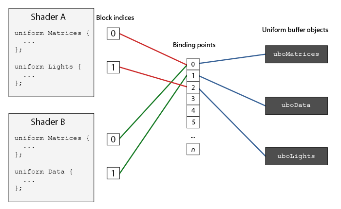
As you can see, we can bind several uniforms-buffers to different anchor points. Since Shader A and Shader B have a uniform block, which is connected to the same anchor point 0, the information uboMatrices in uniform blocks becomes common to them; These shaders are required to define the same Matrices Uniform Block.
To bind a uniform block to a binding point, we need to call glUnifomBlockBinding , which takes the shader program object identifier with the first argument, the uniform block index with the second argument, and the binding point with the third one (where we bind). Uniform block index - index of the location of a specific block in the shader. This information can be obtained by calling glGetUnifromBlocIndex , the host, as arguments the object identifier of the shader program and the name of the uniforms-block. We can bind the uniform-block Lights as in Figure 3 to the anchor point 2 as follows.
unsigned int lights_index = glGetUniformBlockIndex(shaderA.ID, "Lights"); glUniformBlockBinding(shaderA.ID, lights_index, 2); I note that we will have to repeat this for each shader.
OpenGL 4.2 - , , glGetUniformBlockIndex glUniformBlockBinding . - Lights .layout(std140, binding = 2) uniform Lights { ... };
- glBindBufferBase glBindBufferRange .
glBindBufferBase(GL_UNIFORM_BUFFER, 2, uboExampleBlock); // glBindBufferRange(GL_UNIFORM_BUFFER, 2, uboExampleBlock, 0, 152); glBindBufferBase – -. uboExampleBlock 2 2 . glBindBufferRange , – - . glBindBufferRange , - -.
Now everything is set up, we can start adding data to the uniform-buffer. We could add all the data as a single array or update parts of the buffer when we need it, using glBufferSubData . To update the boolean uniforms, we could update the uniforms-buffer like this:
glBindBuffer(GL_UNIFORM_BUFFER, uboExampleBlock); int b = true; // GLSL , glBufferSubData(GL_UNIFORM_BUFFER, 144, 4, &b); glBindBuffer(GL_UNIFORM_BUFFER, 0); The same operation is done with all the uniforms-variables inside the uniforms-block, but with different arguments.
Simple example
Let's demonstrate the true benefit of uniforms. If you look at the previous sections of the code, we used 3 matrices all the time: projections, views and model ones. Of all these matrices, only the model matrix often changes. If we have several shaders using a set of the same matrices, it is probably more beneficial for us to use the uniform-buffer object.
We will store the matrix of the projection and the form in the uniform block - Matrices . We will not store a model matrix here, because it changes quite often in shaders, we would not receive much benefit from such actions.
#version 330 core layout (location = 0) in vec3 aPos; layout (std140) uniform Matrices { mat4 projection; mat4 view; }; uniform mat4 model; void main() { gl_Position = projection * view * model * vec4(aPos, 1.0); } , std 140. 4 , . , , .
- 0. , .
unsigned int uniformBlockIndexRed = glGetUniformBlockIndex(shaderRed.ID, "Matrices"); unsigned int uniformBlockIndexGreen = glGetUniformBlockIndex(shaderGreen.ID, "Matrices"); unsigned int uniformBlockIndexBlue = glGetUniformBlockIndex(shaderBlue.ID, "Matrices"); unsigned int uniformBlockIndexYellow = glGetUniformBlockIndex(shaderYellow.ID, "Matrices"); glUniformBlockBinding(shaderRed.ID, uniformBlockIndexRed, 0); glUniformBlockBinding(shaderGreen.ID, uniformBlockIndexGreen, 0); glUniformBlockBinding(shaderBlue.ID, uniformBlockIndexBlue, 0); glUniformBlockBinding(shaderYellow.ID, uniformBlockIndexYellow, 0); - 0.
unsigned int uboMatrices glGenBuffers(1, &uboMatrices); glBindBuffer(GL_UNIFORM_BUFFER, uboMatrices); glBufferData(GL_UNIFORM_BUFFER, 2 * sizeof(glm::mat4), NULL, GL_STATIC_DRAW); glBindBuffer(GL_UNIFORM_BUFFER, 0); glBindBufferRange(GL_UNIFORM_BUFFER, 0, uboMatrices, 0, 2 * sizeof(glm::mat4)); , glm::mat4 . GLM mat4 GLSL. , , 0.
– . ( ), — . , glBufferSubData :
glm::mat4 projection = glm::perspective(glm::radians(45.0f), (float)width/(float)height, 0.1f, 100.0f); glBindBuffer(GL_UNIFORM_BUFFER, uboMatrices); glBufferSubData(GL_UNIFORM_BUFFER, 0, sizeof(glm::mat4), glm::value_ptr(projection)); glBindBuffer(GL_UNIFORM_BUFFER, 0); Here we put the first part of the uniforms-buffer - the matrix of projections. Before rendering objects, at each iteration of the rendering, we update the second part of the buffer - the view matrix.
glm::mat4 view = camera.GetViewMatrix(); glBindBuffer(GL_UNIFORM_BUFFER, uboMatrices); glBufferSubData(GL_UNIFORM_BUFFER, sizeof(glm::mat4), sizeof(glm::mat4), glm::value_ptr(view)); glBindBuffer(GL_UNIFORM_BUFFER, 0); That's all for uniforms-buffer. Each vertex shader containing Matrices uniform block will now contain data stored in uboMatrices . Now if we drew 4 cubes using 4 different shaders, their projection and view matrices would remain the same.
glBindVertexArray(cubeVAO); shaderRed.use(); glm::mat4 model; model = glm::translate(model, glm::vec3(-0.75f, 0.75f, 0.0f)); // shaderRed.setMat4("model", model); glDrawArrays(GL_TRIANGLES, 0, 36); // ... // ... // ... The only uniform variable we need to set is model . Using uniforms-buffer in such a configuration saves us from calls to setting the value of uniforms for each shader. The result looks something like this:
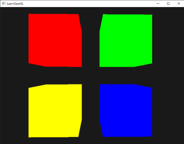
Thanks to different shaders and changing the model matrix, 4 cubes have moved to their parts of the screen and have a different color. This is a relatively simple scenario where we can use uniform buffers, but any other large project with rendering could have over a hundred active shaders; This is exactly the case when uniforms-buffers show themselves in all their glory.
You can find the source code for the sample uniforms here .
- -. -, - – - . -, - , - -. , , - , -. OpenGL . GL_MAX_VETEX_UNIFORM_COMPONENTS. While using uniforms-buffer, this limitation is significantly higher. When you reach the limit of using uniforms, for example, when you are engaged in skeletal animation, you can always use uniforms-buffers.
Source: https://habr.com/ru/post/350156/
All Articles