Microsatellites for Earth Remote Sensing

Currently, there is great interest in the creation and use of small spacecraft — the adequate replacement of large spacecraft.
This is due to the many advantages of microsatellites (MS) [1]:
')
- The relatively low price, as well as the short time required for the development and manufacture of the microsatellite.
- Low cost launch spacecraft. A booster rocket, even of a light class, is capable of putting several microsatellites into orbit.
- For launch, conversion ballistic missiles are used, which, according to the agreements, are destroyed by launching into space with a payload.
- Light space vehicles can be displayed as associated cargo on launch vehicles (RN) or in transport ships that deliver cargo to long-term orbital stations.
- Reducing the risk of large financial losses in case of a microsatellite death in the event of a launch vehicle crash at the start or in the event of its unsuccessful launching to a working orbit.
A microsatellite with a mass of 10 to 100 kg is considered a microsatellite. Thanks to the modern level of development of science and technology, on-board satellite of this class it is possible to install almost all in-house onboard systems: orientation (passive and active), power supply, positioning, radio communications, as well as on-board computing system.
According to Fast Company, two companies, Finnish and American, are preparing to launch entire constellations of low-cost microsatellites, which will multiply the tracking capabilities. Low cost will allow their use by a wider range of clients, which causes concern to many experts [2].
Formulation of the problem
Analysis of the possibilities of using the propulsion system for the correction of the orbit of the Earth remote sensing microsatellites.
Conditions for the supply of microsatellite propulsion.
Microsatellite, suitable for most space tasks, has mass characteristics in the range of 20 ... 70 kg (Lapan TUBSat).
For this range of microsatellite masses, it is possible to use a propulsion system, which is easily coordinated in size and amounts to 7 ... 25% of the satellite mass.
In this case, the propulsion system should have its own power supply system, a control controller, a storage and fuel supply subsystem with a tank with a capacity of up to 3.3 dm3.
The dependence of the orbit altitude increment on the satellite mass
To solve this problem, we use the Tsiolkovsky equation and the expression for calculating the characteristic velocity [3]:
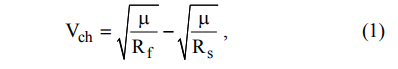
Where
 - gravitational parameter of the attracting center (for the Earth
  ); Rs is the radius of the initial orbit, Rs = 6945 km; Rf is the radius of the final orbit, km.
As a result of transformations, the following expression can be obtained from these equations:
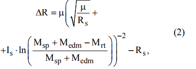
Where
 - increment of the height of the orbit, km; Is - specific engine impulse, Is = 12.750 km / s; Msp is the satellite mass, kg; Medm - the mass of the propulsion system, Medm = 5.33 kg; Mrt is the mass of the working fluid, Mrt = 0.73 kg.
Build a graph:
import numpy as np import matplotlib.pyplot as plt mz=3.986*10**5 # 3/2 Rs=6945 #- . Is=12.750# / Medm=5.33 # . Mrt=0.73 # . # x - . def dR(x): return mz*(((mz/Rs)**0.5+Is*np.log((x+Medm-Mrt)/(x+Medm)))**-2)-Rs p=np.arange(20,50,1) y=[dR(x) for x in p] plt.title(' \n ') plt.ylabel(' .') plt.xlabel(' .') plt.plot(p,y, color='r',linewidth=2) plt.grid(True) plt.show() 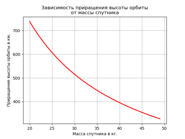
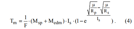
Using the expression (2), one can calculate the maximum increment of the height of the orbit, which can be provided by the propulsion system for the total operating time [3]:

where F is the engine thrust, F = 0.0045 N.
Dependence of maneuver time on intermediate orbit
Determine the maneuver time that may be needed to raise the satellite to any intermediate orbit (Rp) in the range from Rs to Rs +
.To calculate the maneuver time, you can use the following expression [3]:
Build a graph:
import numpy as np import matplotlib.pyplot as plt mz=3.986*10**5 # 3/2 Rs=6945 #- . Is=12.750# / Medm=5.33 # . Mrt=0.73 # . F =0.0045 # # xm - . # Rp - . def dR(xm,Rp): m=(np.sqrt(mz/Rp)-np.sqrt(mz/Rs))/Is return(1/(F*3600))*(xm+Medm)*Is*1000*(1-np.e**m) p=np.arange(6945,7245,1) y1=[dR(50,Rp) for Rp in p] y2=[dR(20,Rp) for Rp in p] plt.title(' \n ') plt.ylabel(' .') plt.xlabel(' .') plt.plot(p,y1, color='r',linewidth=2, label='50 .') plt.plot(p,y2, color='b',linewidth=2, label='20 .') plt.legend(loc='best') plt.grid(True) plt.show() 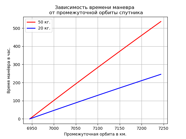
The capabilities of the propulsion system to change the orbital plane.
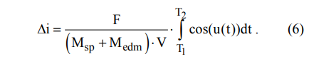
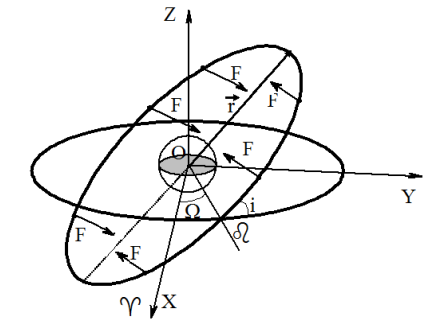
To calculate the change in inclination of the orbit under the influence of small thrusters, you can use the following expression [4]:

where V is the orbital speed of movement, m / s; i - orbit inclination; u is the satellite latitude argument. We write this expression in the integral form:
From this expression it is seen that to increase or decrease the inclination of the orbit, the engine thrust should
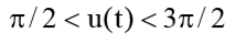 act in one direction and when
  and
and 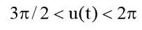 changes its direction to the opposite.
Thrust should be perpendicular to the orbital plane. The figure shows the required direction of engine thrust at various points as the inclination increases for orbits with direct motion.
findings
The analysis of the possibilities of using the propulsion system for the correction of the orbit of the Earth remote sensing microsatellites has been carried out.
- Microsatellites.
- Microsatellites will watch around the clock anywhere in the world.
- Balk, M. B. Elements of the dynamics of space flight [Text] / M. B. Balk. - M .: Science, 1965. - 339 p.
- Levantovsky, V.I. The mechanics of space flight in an elementary presentation [Text] / V.I. Levantovsky. - M .: Science, 1974. - 512 p.
Source: https://habr.com/ru/post/349844/
All Articles