The first step to hardware accelerators of neural networks for programmers is through learning the basics of HDL, RTL and a lab on FPGA
Kazan University Innopolis as an experiment teaches computer programmers how to develop hardware. Moreover, the development of a hardware means not programming microcontrollers inside, say robots, but designing digital circuits at the register transfer level (RTL), using hardware description languages (HDL) and laboratory classes on programmable logic integrated circuits (FPGA / FPGA - Field Programmable Gate Array).
Why do programmers need it? After all, electronics is taught at (much less popular) electronics departments, where a student first studies the physics of electricity, analog circuits, makes a couple of labs with multiplexers, after which all of this is forgotten and goes to work as a programmer.
One of the reasons why digital circuitry is for a programmer is the recent boom of neural networks. If you want complex network training to take not weeks / days / hours, but hours / minutes / seconds, you cannot do without hardware accelerators. Only a specialized hardware will perform in parallel a large number of small precision multiplications with simultaneous transactions to the ocean of memory. In the future, we are waiting for specialized ASIC (application-specific integrated circuits) for AI, and everywhere. They will have both a traditional processor and large AI blocks on board, with the possibility of partial reconfiguration.
')
From Google and Microsoft to Skolkovo and Innopolis, there is a growing understanding that we need specialists who can build such co-processors. They should own a hardware microarchitecture, along with an understanding of the software ecosystem and algorithms. And possession of micro-architecture is based on understanding the level of register transfers. How it is implemented now in Innopolis:
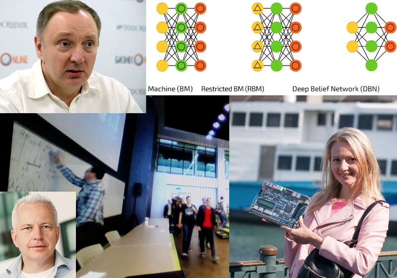
The course of computer architecture in Innopolis is developed by his rector Alexander Tormasov, along with foreign specialists invited to Kazan: Italian professor Giancarlo Succi, who works as a dean in Innopolis, and Muhammad Fahim, who before Innopolis worked at universities in South Korea and Pakistan.
Rector Tormasov before Innopolis worked as the head of the department of computer science at MIPT and headed the advanced development department of SWsoft (later Parallels), where he was engaged in virtualization. Paralells is one of the few Russian companies widely known in America - at least a couple of American engineers were surprised when I told them that Parallels is a Russian company, they thought it was an American company. In addition, Tormasov heads the Russian branch of the IEEE Computer Society.
Tormasov liked to introduce all sorts of newfangled things 30 years ago - then he taught MIPT students how to use Unix, shell, awk, etc. Linux was not there yet, and Unix was on Australian Labtam computers with a National Semicondustor NS32000 processor. Before Tormasov, students worked on BESM-6 with FORTRAN and punched cards.
So, recently Tormasov asked me to skype a couple of lectures on HDL, RTL and FPGA for his computer architecture course. He has more than 200 students attending these lectures, so the experiment has a good sample. Lectures Tormasov asked to read in English, apparently because 1) there are foreign students in Innopolis 2) Giancarlo Succi and Muhammad Fahim also read English and 3) students need to train comprehension, including my heavy Ukrainian accent.
The purpose of the first lecture was to give students enough information so that they could simulate the simplest scheme on a software simulator, as well as synthesize this scheme and configure the FPGA with it. It was also necessary to visually show that the scheme is not a program:
Slides of the first lecture in PDF format.
The purpose of the second lecture was to give an overview of what awaits them if they want to dig deeper into the topic of digital logic. They need to understand the concept of a D-flip-flop, sequential logic, a finite state machine, and a pipeline. Then they can make interesting schemes that repeat actions, transmit information from sensors, etc. - right up to the processor cores and beyond.
Slides of the second lecture in PDF format.
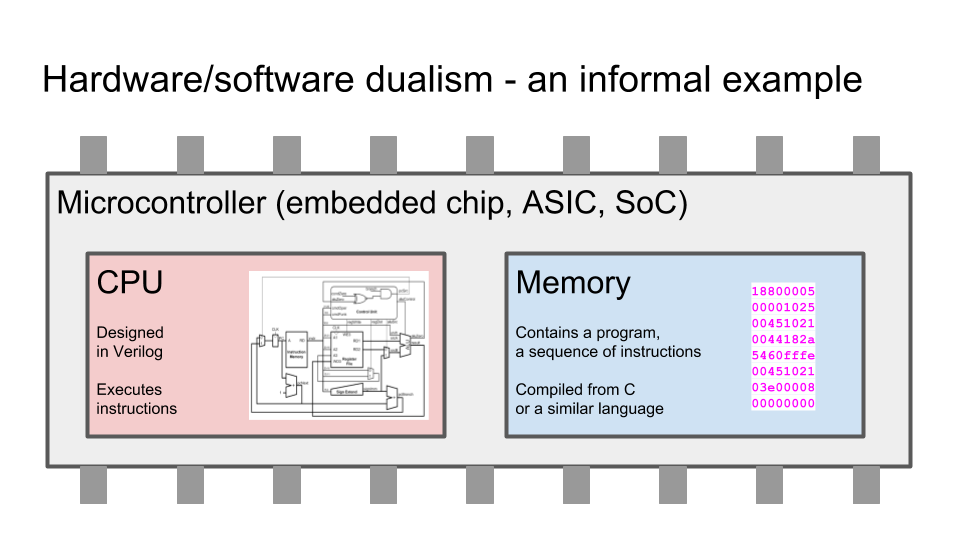
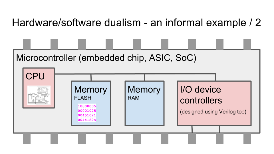
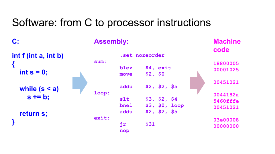
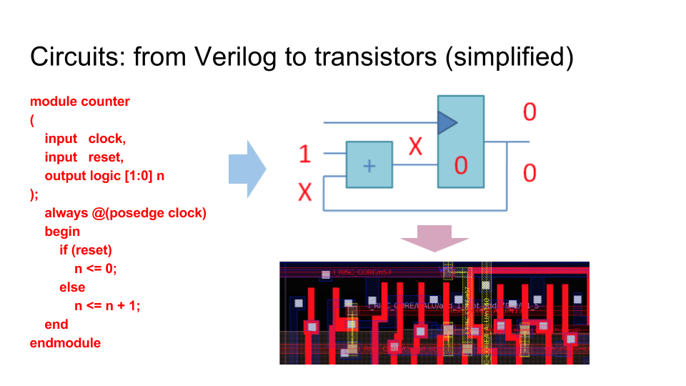
Several key slides. The difference between schemes and programs. Programming languages (for example, C) are compiled into chains of instructions that the processor selects from memory. Hardware description languages (for example, Verilog) are synthesized into a graph from logical elements, which ultimately turn into transistors and tracks on a microcircuit, which is baked at the factory:
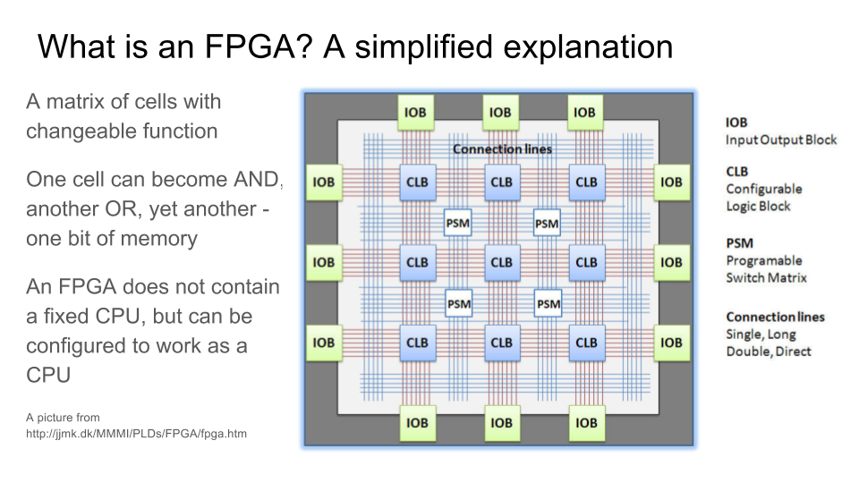
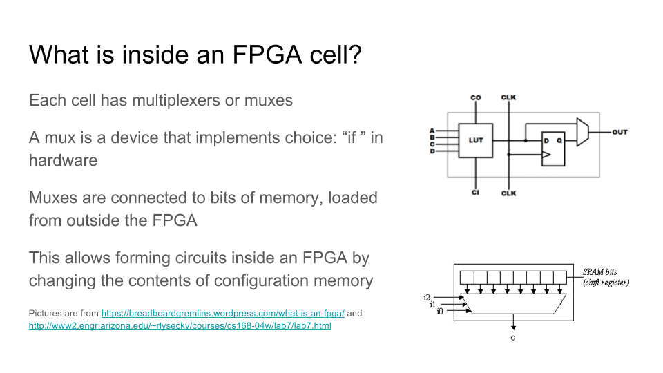
How the FPGA / FPGA works - a matrix of logic elements, the function of which can be changed using multiplexers connected to the bits of the configuration memory:
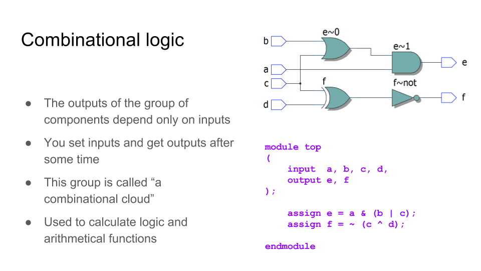
The simplest scheme. Combination logic - we put some data on the input, after some time (with a propagation delay) we get the answer at the output.
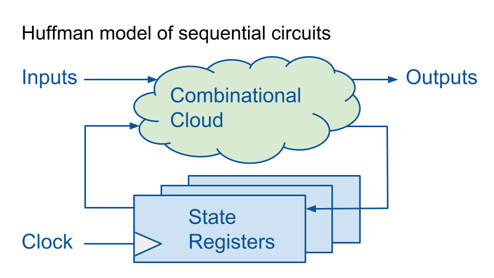
The Huffman model is convenient for introducing sequential logic. Combination logic connects to registers - memory elements.
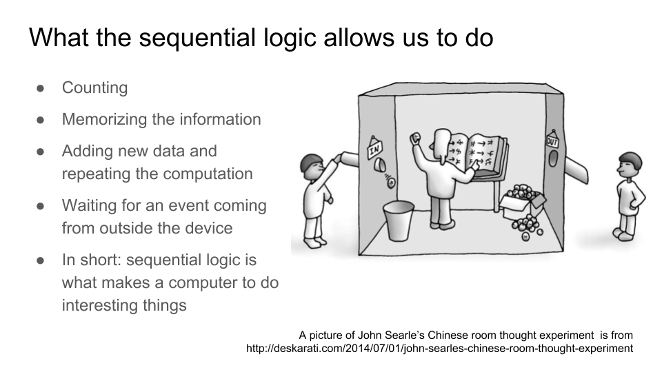
Sequential logic allows computing devices to do non-trivial things. Without it, only on combinational logic, we could only calculate tables of functions, the values of which are uniquely determined from the arguments. Sequential logic adds a current state to the schema, as a result of which we can count, wait for events, repeat operations based on old and new data, etc. Here I refer to the “Chinese room” - a popular paradox that emerges when discussing the topic “Can a car think?” The Chinese room is in fact one of the implementations of the Huffman model, the generalization of the finite state machine:
The main concept that you need to understand in the introductory course of digital circuitry is the function of the D-flip-flop, the basic state element. If the logical elements AND-OR-NOT can, in principle, be explained even to children in kindergarten, then with D-triggers, students have a mental barrier. And not only among schoolchildren, but also programmers with experience who are prevented from understanding digital logic by the mental model of program execution as chains of instructions that have firmly grown into their brains. Instead, you need to use a mental model in which many events occur simultaneously, for example, simultaneous recording of thousands or millions of D-flip-flops.
A D-flip-flop is a device that stores 1 bit of information during one clock cycle. It has three main external signals - a clock signal (clock, CLK), an input for recording (D) and an output for reading (Q). At the output Q, the stored state of the D-flip-flop is output, and the D-flip-flop ignores the input D for almost the entire cycle. Input D is recorded in the current state during a short blink of the aperture (aperture), when the clock signal CLK changes from zero to one. By the time of the aperture, when the clock frequency is correctly selected, at the input of the D-flip-flop there is a settled calculation result of the combinational logic. Until that moment, any garbage may be at the entrance, since the calculations in the equipment do not occur instantaneously.
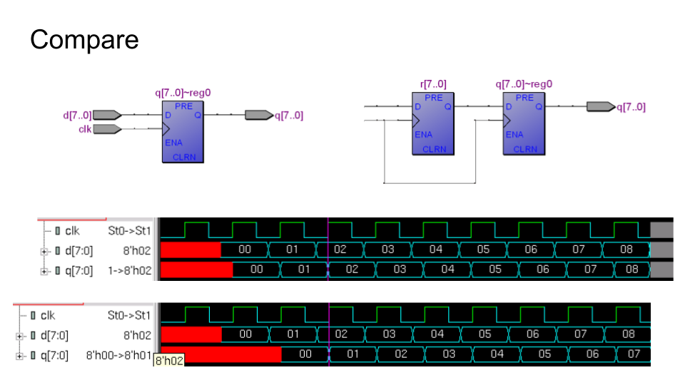
From D-triggers are built registers, storage for sets in several bits. At the output of the register, the whole cycle is the value written to it in the previous cycle. If you put the registers one by one, the output from this combination will be the value from the previous-previous cycle:
If you combine the combinational adder and register, you get a counter. In this animation, X means “untapped value”. The frequency of the clock signal is chosen so that writing to the register takes place when the addition with the unit is guaranteed to end, and you need to write the amount into the register. This amount will be used as one of the following in the following cycle:
Then there are slides about the state machines that I made on the basis of the Digital Circuit Design and Computer Architecture books. David M. Harris, Sarah L. Harris. And then a few slides about the principle of conveyor processing.
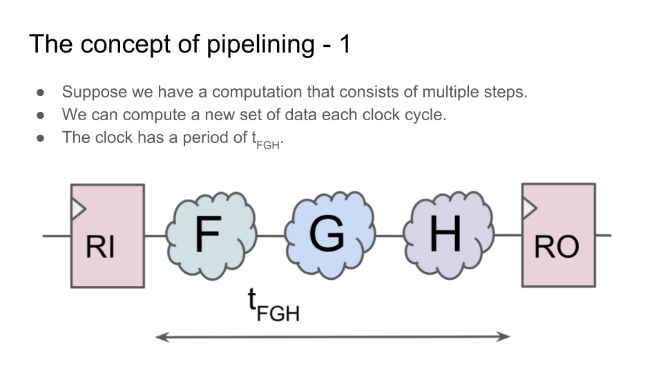
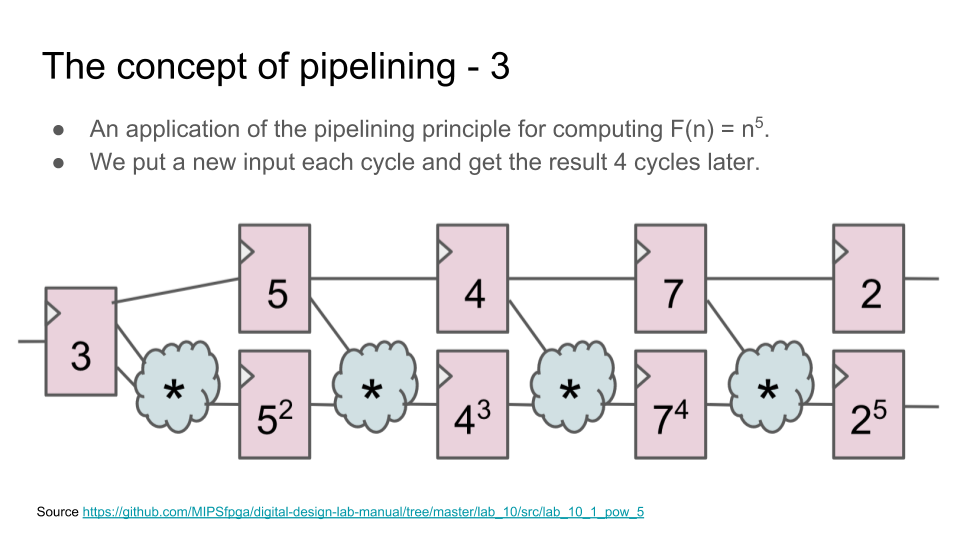
Conveyor is one of the key concepts of modern digital electronics development. The pipeline arises not only in the design of the processor (execution pipe), but also in anything: in the design of the arithmetic unit, in the block for transactions to the memory, in the processing of packets inside the router chip, and in the shaders for three-dimensional graphics. The easiest way to explain the basic idea of a pipeline is by the example of an arithmetic unit, for example, a block for exponentiation.
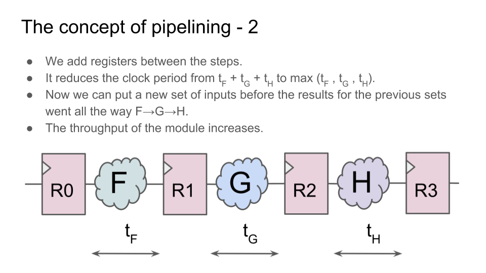
We take some operation that can be divided into several successive steps. Now, instead of performing all the steps in one cycle, we put registers between the steps. Although now the operation is performed not in one cycle, but in several, but:
1) the circuit can operate at a higher clock frequency;
2) while the operands for the new calculation can be fed to the input immediately after the first cycle of the previous calculation, without waiting for the end of all cycles of the previous calculation;
3) therefore, the total capacity of the block will be higher than that of the block in which the calculations are performed in one cycle:
Video of the second lecture:
Now about the boards for laboratory work. Since the course was only introduced as an experiment, the budget for the FPGA board in Innopolis was not allocated. I lent Innopolis 10 fees that I bought for my money, but there is a catastrophic shortage of fees (there are 210 students in the course). “Give more circuit boards!” Is the most frequent feedback from students on labs with FPGA.
In principle, teachers are distributed by Intel / Altera boards, less frequently by Xilinx, but in small quantities. Universities buy fees from Xilinx and Altera and for their money, but quite often this is due to bureaucracy and red tape. Kiev Polytechnic Institute in the face of Yevgeny Korotky recently bought FPGA boards for a grant from the Kiev municipality to train FPGA schoolchildren. Zelenograd enterprise Elvis-NeoTek, Moscow company NauTech, St. Petersburg Macro Group and California MIPS allocated FPGA boards to universities for educational needs (MSU, MIET, ITMO, MEI, KPI, and others). But in order to update all programs in central and regional universities and make RTL understanding part of general education in high-tech (as it is done in American universities and as Chinese people in China do it quickly), you need two orders of magnitude more fees. On the one hand, this is a problem, but on the other hand, the opportunity for regional companies and individuals to engage in charity work in relation to their local universities and physical education schools. Mass ownership of these technologies can have far-reaching consequences for Russia and other countries in the region - something like the introduction of computer science in Soviet schools in 1985 led to Yandex and other developed Russian software companies in the 21st century.
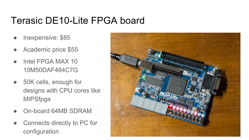
Virtually any boards (Xilinx, Altera, Lattice, etc.) are suitable for basic exercises in the development of digital logic at the register transfer level. In Innopolis, we are now using the Terasic DE10-Lite board. It is inexpensive and is suitable even for the synthesis of small industrial processor cores (if you want to experiment with this, this is the next level):
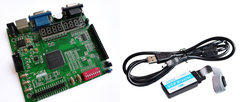
But if you buy hundreds of motherboards in the conditions of lack of money, then one of the solutions is to take payments from Ali Express with not the latest FPGAs. True, for some of them, it will be necessary to use not the latest version of software for synthesis, but by and large it does not matter. Also, they are not the most convenient switches and they are few, but they cost around twenty dollars (thousands of rubles). For Intel / Altera FPGA boards, you need a USB Blaster adapter, and it’s better to buy it separately - some USB Blaster on AliExpress work with the latest Intel Quartus software, version 17.1, but others are only compatible with 2013 version 13.0sp1.
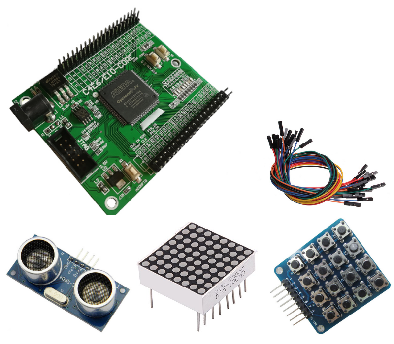
Even cheaper is to buy FPGA boards without peripherals. This can be interesting for schoolchildren, especially if they have all kinds of sensors, range finders, LED arrays, speakers and other devices that can be connected to the FPGA board and make attractive projects on it. For schoolchildren, it may be interesting to do the same project first with chips of a small degree of integration, then with FPGA, then with a microcontroller.
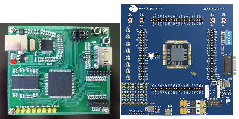
Finally, in addition to Terasic, Digilent and other Asian, American and European manufacturers of motherboards, there are also Russian ones: the Mars rover and the FPGA manufacturing plant in Voronezh. On the site of the Rover there are quite good instructions for educational projects. They can develop into one of the centers of the Russian community in this area. FPGAs from Voronezh are expensive, but if the Voronezh plant distributes them to universities, then you can also do all these exercises on them.
Why do programmers need it? After all, electronics is taught at (much less popular) electronics departments, where a student first studies the physics of electricity, analog circuits, makes a couple of labs with multiplexers, after which all of this is forgotten and goes to work as a programmer.
One of the reasons why digital circuitry is for a programmer is the recent boom of neural networks. If you want complex network training to take not weeks / days / hours, but hours / minutes / seconds, you cannot do without hardware accelerators. Only a specialized hardware will perform in parallel a large number of small precision multiplications with simultaneous transactions to the ocean of memory. In the future, we are waiting for specialized ASIC (application-specific integrated circuits) for AI, and everywhere. They will have both a traditional processor and large AI blocks on board, with the possibility of partial reconfiguration.
')
From Google and Microsoft to Skolkovo and Innopolis, there is a growing understanding that we need specialists who can build such co-processors. They should own a hardware microarchitecture, along with an understanding of the software ecosystem and algorithms. And possession of micro-architecture is based on understanding the level of register transfers. How it is implemented now in Innopolis:
The course of computer architecture in Innopolis is developed by his rector Alexander Tormasov, along with foreign specialists invited to Kazan: Italian professor Giancarlo Succi, who works as a dean in Innopolis, and Muhammad Fahim, who before Innopolis worked at universities in South Korea and Pakistan.
Rector Tormasov before Innopolis worked as the head of the department of computer science at MIPT and headed the advanced development department of SWsoft (later Parallels), where he was engaged in virtualization. Paralells is one of the few Russian companies widely known in America - at least a couple of American engineers were surprised when I told them that Parallels is a Russian company, they thought it was an American company. In addition, Tormasov heads the Russian branch of the IEEE Computer Society.
Tormasov liked to introduce all sorts of newfangled things 30 years ago - then he taught MIPT students how to use Unix, shell, awk, etc. Linux was not there yet, and Unix was on Australian Labtam computers with a National Semicondustor NS32000 processor. Before Tormasov, students worked on BESM-6 with FORTRAN and punched cards.
So, recently Tormasov asked me to skype a couple of lectures on HDL, RTL and FPGA for his computer architecture course. He has more than 200 students attending these lectures, so the experiment has a good sample. Lectures Tormasov asked to read in English, apparently because 1) there are foreign students in Innopolis 2) Giancarlo Succi and Muhammad Fahim also read English and 3) students need to train comprehension, including my heavy Ukrainian accent.
The purpose of the first lecture was to give students enough information so that they could simulate the simplest scheme on a software simulator, as well as synthesize this scheme and configure the FPGA with it. It was also necessary to visually show that the scheme is not a program:
Slides of the first lecture in PDF format.
The purpose of the second lecture was to give an overview of what awaits them if they want to dig deeper into the topic of digital logic. They need to understand the concept of a D-flip-flop, sequential logic, a finite state machine, and a pipeline. Then they can make interesting schemes that repeat actions, transmit information from sensors, etc. - right up to the processor cores and beyond.
Slides of the second lecture in PDF format.
Several key slides. The difference between schemes and programs. Programming languages (for example, C) are compiled into chains of instructions that the processor selects from memory. Hardware description languages (for example, Verilog) are synthesized into a graph from logical elements, which ultimately turn into transistors and tracks on a microcircuit, which is baked at the factory:
How the FPGA / FPGA works - a matrix of logic elements, the function of which can be changed using multiplexers connected to the bits of the configuration memory:
The simplest scheme. Combination logic - we put some data on the input, after some time (with a propagation delay) we get the answer at the output.
The Huffman model is convenient for introducing sequential logic. Combination logic connects to registers - memory elements.
Sequential logic allows computing devices to do non-trivial things. Without it, only on combinational logic, we could only calculate tables of functions, the values of which are uniquely determined from the arguments. Sequential logic adds a current state to the schema, as a result of which we can count, wait for events, repeat operations based on old and new data, etc. Here I refer to the “Chinese room” - a popular paradox that emerges when discussing the topic “Can a car think?” The Chinese room is in fact one of the implementations of the Huffman model, the generalization of the finite state machine:
The main concept that you need to understand in the introductory course of digital circuitry is the function of the D-flip-flop, the basic state element. If the logical elements AND-OR-NOT can, in principle, be explained even to children in kindergarten, then with D-triggers, students have a mental barrier. And not only among schoolchildren, but also programmers with experience who are prevented from understanding digital logic by the mental model of program execution as chains of instructions that have firmly grown into their brains. Instead, you need to use a mental model in which many events occur simultaneously, for example, simultaneous recording of thousands or millions of D-flip-flops.
A D-flip-flop is a device that stores 1 bit of information during one clock cycle. It has three main external signals - a clock signal (clock, CLK), an input for recording (D) and an output for reading (Q). At the output Q, the stored state of the D-flip-flop is output, and the D-flip-flop ignores the input D for almost the entire cycle. Input D is recorded in the current state during a short blink of the aperture (aperture), when the clock signal CLK changes from zero to one. By the time of the aperture, when the clock frequency is correctly selected, at the input of the D-flip-flop there is a settled calculation result of the combinational logic. Until that moment, any garbage may be at the entrance, since the calculations in the equipment do not occur instantaneously.
From D-triggers are built registers, storage for sets in several bits. At the output of the register, the whole cycle is the value written to it in the previous cycle. If you put the registers one by one, the output from this combination will be the value from the previous-previous cycle:
If you combine the combinational adder and register, you get a counter. In this animation, X means “untapped value”. The frequency of the clock signal is chosen so that writing to the register takes place when the addition with the unit is guaranteed to end, and you need to write the amount into the register. This amount will be used as one of the following in the following cycle:
Then there are slides about the state machines that I made on the basis of the Digital Circuit Design and Computer Architecture books. David M. Harris, Sarah L. Harris. And then a few slides about the principle of conveyor processing.
Conveyor is one of the key concepts of modern digital electronics development. The pipeline arises not only in the design of the processor (execution pipe), but also in anything: in the design of the arithmetic unit, in the block for transactions to the memory, in the processing of packets inside the router chip, and in the shaders for three-dimensional graphics. The easiest way to explain the basic idea of a pipeline is by the example of an arithmetic unit, for example, a block for exponentiation.
We take some operation that can be divided into several successive steps. Now, instead of performing all the steps in one cycle, we put registers between the steps. Although now the operation is performed not in one cycle, but in several, but:
1) the circuit can operate at a higher clock frequency;
2) while the operands for the new calculation can be fed to the input immediately after the first cycle of the previous calculation, without waiting for the end of all cycles of the previous calculation;
3) therefore, the total capacity of the block will be higher than that of the block in which the calculations are performed in one cycle:
Video of the second lecture:
Now about the boards for laboratory work. Since the course was only introduced as an experiment, the budget for the FPGA board in Innopolis was not allocated. I lent Innopolis 10 fees that I bought for my money, but there is a catastrophic shortage of fees (there are 210 students in the course). “Give more circuit boards!” Is the most frequent feedback from students on labs with FPGA.
In principle, teachers are distributed by Intel / Altera boards, less frequently by Xilinx, but in small quantities. Universities buy fees from Xilinx and Altera and for their money, but quite often this is due to bureaucracy and red tape. Kiev Polytechnic Institute in the face of Yevgeny Korotky recently bought FPGA boards for a grant from the Kiev municipality to train FPGA schoolchildren. Zelenograd enterprise Elvis-NeoTek, Moscow company NauTech, St. Petersburg Macro Group and California MIPS allocated FPGA boards to universities for educational needs (MSU, MIET, ITMO, MEI, KPI, and others). But in order to update all programs in central and regional universities and make RTL understanding part of general education in high-tech (as it is done in American universities and as Chinese people in China do it quickly), you need two orders of magnitude more fees. On the one hand, this is a problem, but on the other hand, the opportunity for regional companies and individuals to engage in charity work in relation to their local universities and physical education schools. Mass ownership of these technologies can have far-reaching consequences for Russia and other countries in the region - something like the introduction of computer science in Soviet schools in 1985 led to Yandex and other developed Russian software companies in the 21st century.
Virtually any boards (Xilinx, Altera, Lattice, etc.) are suitable for basic exercises in the development of digital logic at the register transfer level. In Innopolis, we are now using the Terasic DE10-Lite board. It is inexpensive and is suitable even for the synthesis of small industrial processor cores (if you want to experiment with this, this is the next level):
But if you buy hundreds of motherboards in the conditions of lack of money, then one of the solutions is to take payments from Ali Express with not the latest FPGAs. True, for some of them, it will be necessary to use not the latest version of software for synthesis, but by and large it does not matter. Also, they are not the most convenient switches and they are few, but they cost around twenty dollars (thousands of rubles). For Intel / Altera FPGA boards, you need a USB Blaster adapter, and it’s better to buy it separately - some USB Blaster on AliExpress work with the latest Intel Quartus software, version 17.1, but others are only compatible with 2013 version 13.0sp1.
Even cheaper is to buy FPGA boards without peripherals. This can be interesting for schoolchildren, especially if they have all kinds of sensors, range finders, LED arrays, speakers and other devices that can be connected to the FPGA board and make attractive projects on it. For schoolchildren, it may be interesting to do the same project first with chips of a small degree of integration, then with FPGA, then with a microcontroller.
Finally, in addition to Terasic, Digilent and other Asian, American and European manufacturers of motherboards, there are also Russian ones: the Mars rover and the FPGA manufacturing plant in Voronezh. On the site of the Rover there are quite good instructions for educational projects. They can develop into one of the centers of the Russian community in this area. FPGAs from Voronezh are expensive, but if the Voronezh plant distributes them to universities, then you can also do all these exercises on them.
Source: https://habr.com/ru/post/349750/
All Articles