STM32 blink ++ or read incremental encoder data
Motivation
A couple of months ago I was telling how the incremental encoder works and how to read the angle with the help of the simplest arduine. Of course, I immediately received these comments:

I have arduino brain. I personally don’t use Arduino myself, but I still think that this is a very useful thing. I heard a lot of horror about how to start with stm32, and did not want to get into it. On the other hand, in recent times, comments have been heard more and more often that the toolkit has been finished and, in general, everything is in chocolate. I decided to try how long it would take for me to do the simplest type of project by blinking with a LED. I bought a blue pill , bought a Chinese analog debugger st-link v2, and sat down with it all to figure it out.
')
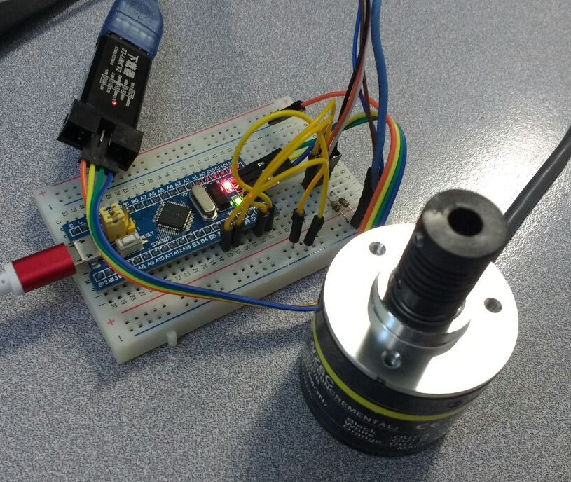
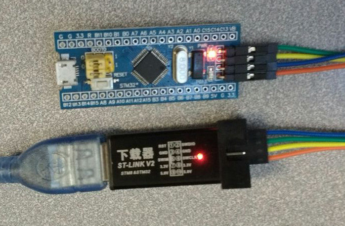
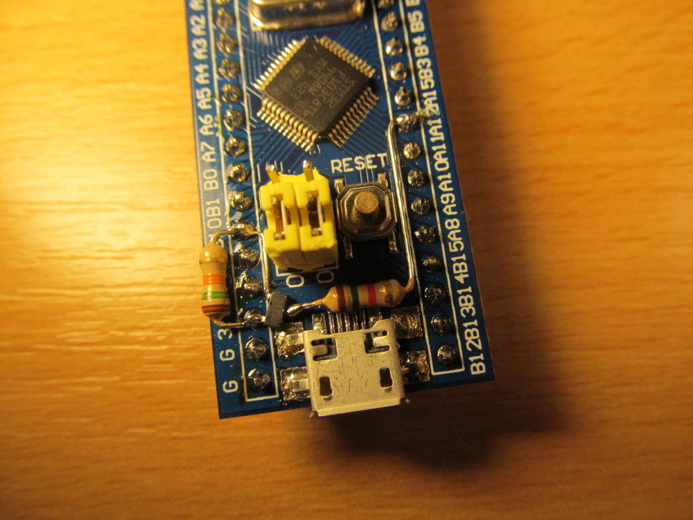
Looking ahead, this is what the piece of iron in question looks like:
Let's go: setting up the project
As a development environment, I chose System Workbench for STM32 , this is an eclipse with pre-installed plugins for working with stm32. The second software, which is very convenient to use, is STM32CubeMX . In the ideal case, nothing else is needed. It is enough to register on these two sites, download the software, click on the buttons "ok."
And then the fun begins. The Internet is very poor in tutorials that work . Therefore, I’ll show the entire clickcode that allowed me to run my code. I feel that I myself will return to this post.
Run STM32CubeMX, drive in our processor and click on the start project button:

STM32CubeMX is a software in which we configure the legs of the processor, and then we get a ready-made code template in which everything is already configured, we just need to use it.
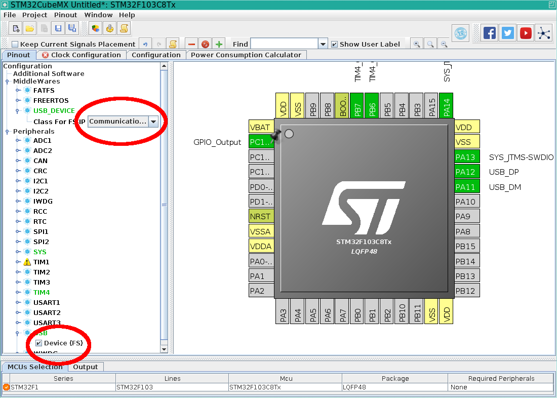
Most blue tablets have a LED on PC13 pin, so how can we do without it, configure it in GPIO_OUTPUT:

We want the debugging process to work, so we put the serial wire in SYS:

I decided to hang the encoder on TIM4 timer, put it in this mode. Please note that SOME processor inputs are 5 volt tolerant (five volt tolerant, FT), and specifically PB6 / PB7 allow you to connect a five volt encoder.

I like to output data to the good old virtual serial port, just like in Arduin, so we click a couple more times:
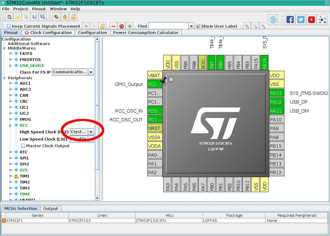
The processor will receive a shred from the external resonator:
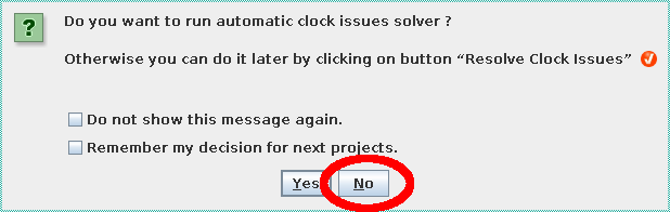
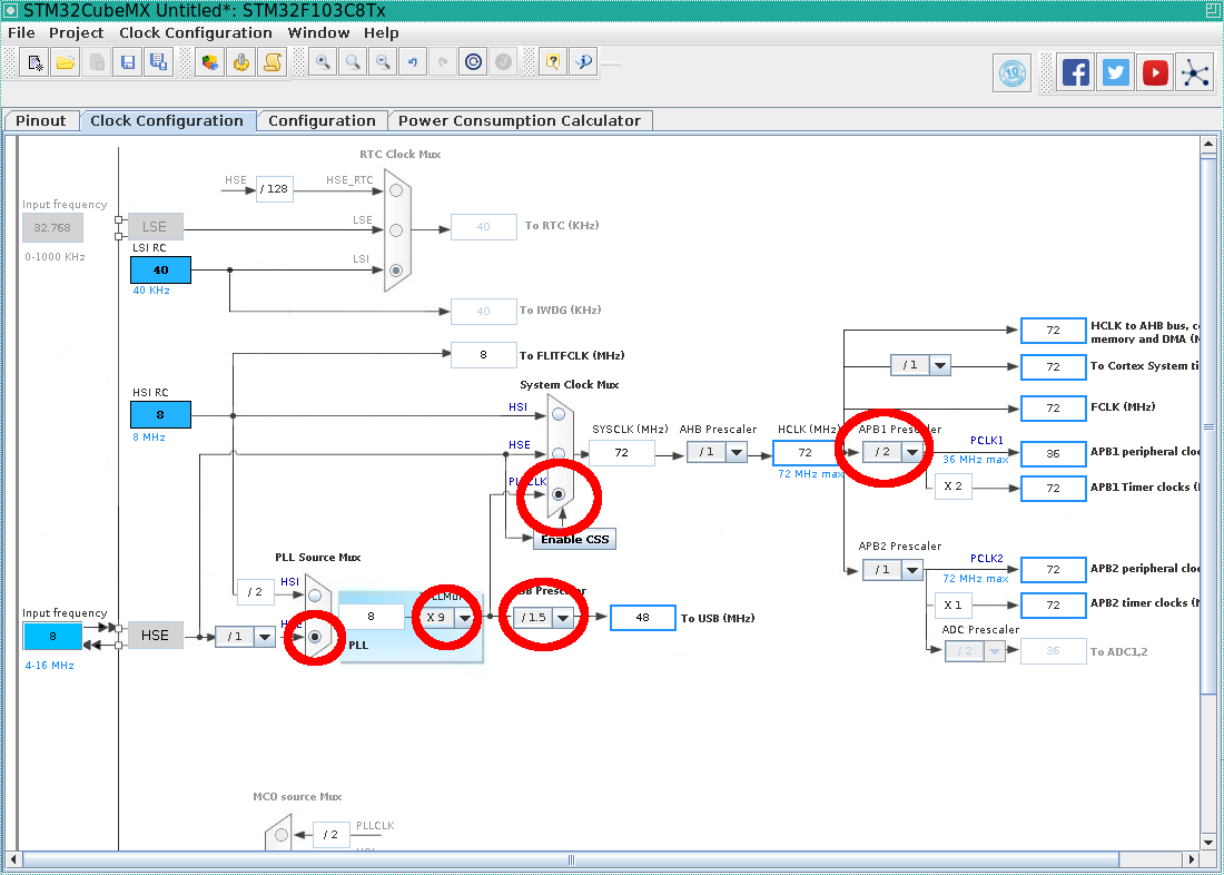
Now the legs are more or less apart, it's time to place the shreds. Go to the clock configuration tab, and discard the automatic assistant:
Then we put up any dividers as follows:
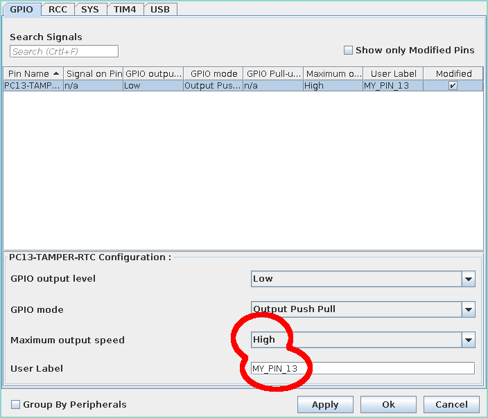
Next configuration-> GPIO customize leg GPIO:
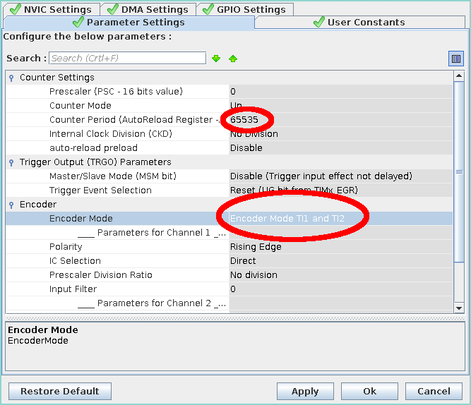
and in configuration-> TIM4 we set the timer so that it counts in 4x mode (see my previous article , it explains what it is)
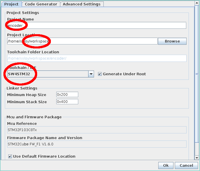
After that, in the project settings, we set up directories and the fact that the code should be generated under System Workbench for STM32:
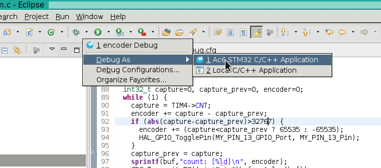
Then we generate the code, and open the eclipse. First of all we click here:
And then we are ready to write code.
Directly code and debug
This is how the only code that I wrote with my hands looks like, everything is pretty transparent in it:
int main(void) { HAL_Init(); SystemClock_Config(); MX_GPIO_Init(); MX_TIM4_Init(); MX_USB_DEVICE_Init(); HAL_TIM_Encoder_Start(&htim4, TIM_CHANNEL_ALL); char buf[25]; int32_t capture=0, capture_prev=0, encoder=0; while (1) { capture = TIM4->CNT; encoder += capture - capture_prev; if (abs(capture-capture_prev)>32767) { encoder += (capture<capture_prev ? 65535 : -65535); HAL_GPIO_TogglePin(MY_PIN_13_GPIO_Port, MY_PIN_13_Pin); } capture_prev = capture; sprintf(buf,"count: [%ld]\n", encoder); CDC_Transmit_FS((uint8_t *)buf, strlen(buf)); HAL_Delay(100); } } The only subtlety is that the blue tablet has all 16-bit counters, and my encoder generates 10,000 events per revolution. Therefore, I track the overflow of the counter value with my hands, my code assumes that the encoder does not generate 32k pulses between two readings of the counter, I was frankly lazy to write interrupt-event handlers for overflow / underflow events. My LED changes its state at every overflow, do we have a blink or not?
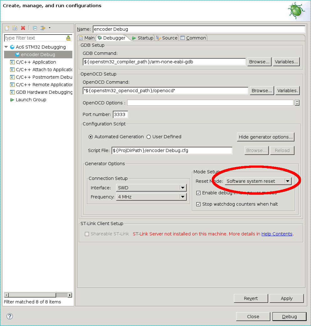
Everything seems to be ready, so we compile the project and run the debugger:
The blue tablet itself is stuck in usb, from it there are 3 wires to the Chinese stlink, which is also in turn stuck in usb. The encoder receives 5V power from USB. If everything went well, the debugger will start and we will have the virtual port / dev / ttyACM0 on our system.
I rotate the encoder shaft with my fingers, do cat / dev / ttyACM0 and enjoy reading the correct encoder:

If you just want to make a blink / similar, then the minimum connection of the blue tablet looks like this:
And if all is not well?
USB
To get to this point, it took me three full days. What took so much time? For example, if I reintroduce the code to the blue tablet, it will work well, debugging too, the serial port will be present in the system, but nothing will come from it. If you tap the usb cord, then everything will be fine.
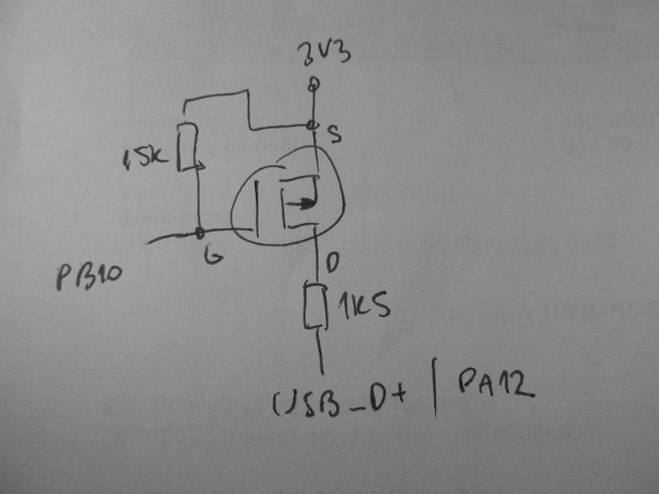
Long googling leads to the fact that there are problems in the PCB layout, and moreover, most often it has the wrong resistor :
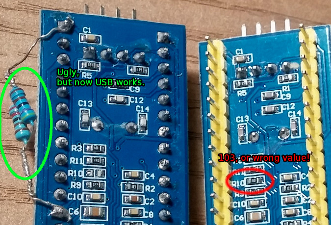
Replacing this resistor helped me on half of the computers. More attentive googling shows this . Here is the suggested fix:
I was content with a program resetting of the device. Here is the code, it is enough for it to make cc usbreset.c:
Hidden text
/* usbreset -- send a USB port reset to a USB device */ #include <stdio.h> #include <unistd.h> #include <fcntl.h> #include <errno.h> #include <sys/ioctl.h> #include <linux/usbdevice_fs.h> int main(int argc, char **argv) { const char *filename; int fd; int rc; if (argc != 2) { fprintf(stderr, "Usage: usbreset device-filename\n"); return 1; } filename = argv[1]; fd = open(filename, O_WRONLY); if (fd < 0) { perror("Error opening output file"); return 1; } printf("Resetting USB device %s\n", filename); rc = ioctl(fd, USBDEVFS_RESET, 0); if (rc < 0) { perror("Error in ioctl"); return 1; } printf("Reset successful\n"); close(fd); return 0; } And this is his work:
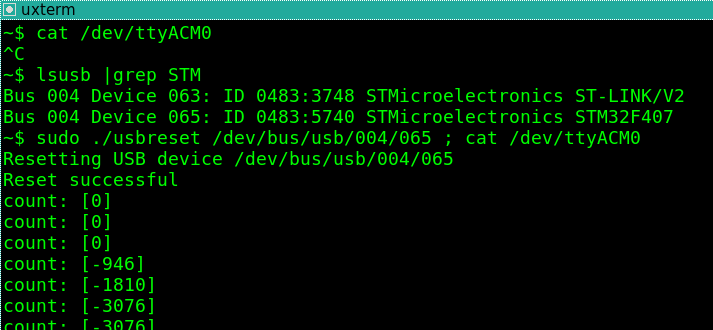
Please note that at first nothing was received from the port, after the soft reset everything was fixed.
SWD
What else could be the problem? For example, idle debugger:
I couldn’t fill the code for a very long time, and when I could, I first had to set the jumpers to boot0 = 1, boot1 = 0, fill the code, and then rearrange the jumpers back. Given that the normal position of jumpers is boot0 = boot1 = 0. This is because SWD has been disabled in the processor, note that we specifically included it in the STM32CubeMX. But we turned it on, and the board could have come with SWD turned off, where the whistle came from.
Bootloader
If suddenly someone decides that the Arduino environment has already been dubbed under Stm, then keep in mind that the bootloader will most likely not be queried.
Write protection
In one of the boards I bought, I was simply protected from writing a flash. The only way I know how to fix it is to install the STM32 ST-LINK Utility under Windows and completely wipe the memory. Linux pribludy not help.
Just dead boards
And it happens so. And it somehow moves, but partially dead. How to distinguish it from its curved hands is not very clear.
SWO: Serial wire output
Do you have an official demo fee and you are used to making information output through SWO? With the Chinese clone directly this ficus will not pass, do not waste time, here is a fix:
Conclusion
And many, many other problems, each of which, in principle, can be solved. For example, the fact that stm32 errata (if exists) is often longer than the datasheet itself ...
Nowhere is there a systematic information for beginners, the simplest flasher LED instantly turns into a headache. Yes, now I figured it out a little, and I really hope that I can continue to develop with fewer problems, I even have a debugger for sure.
In general, I do not regret the time spent, and the next project will be sawed on stm32. But now it is completely clear to me why such blue pills have significantly less community. If you do not need a headache, but you just need a working iron, then do not be fooled by advertising, they say, it is all cheap. Buy real programmers and real developer boards. And even in general stay in the Arduino environment, there are a lot of tasty things in it.
Source: https://habr.com/ru/post/349738/
All Articles