CC1101 running a PIC controller or building a peer-to-peer network for a radio engineer (part 2, continued)
After the survey, time passed ... I apologize for the delay: it is difficult to find time.
In the process of writing this text, there were so many subtleties that I would like to describe that it can pull on a little work :-). So I decided to publish material chapter by chapter at a time. Only after complete exhaustion of questions and clarifications on a specific chapter will the following be published.
So, you need to build a simple network, the form of which is presented in the following figure. It is desirable to build a network without using expensive spectrum analyzers and other equipment for the analysis of radio engineering circuits. It is also desirable that the software is sufficiently transparent and as simple as possible.
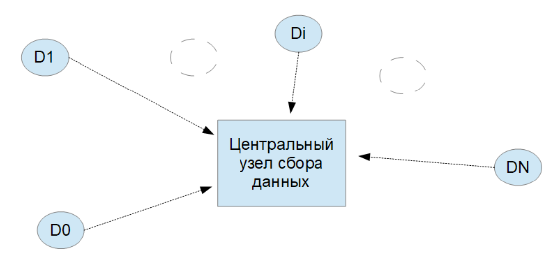
It is assumed that the D0 ... Di ... DN sensors are self-powered, and the data acquisition device is connected to the mains or some other source with respect to unlimited power.
In this work, an attempt is made (regular :)) to systematize approaches to building such a simple peer-to-peer network for collecting data from autonomous sensors from the point of view of a radio engineer who has only basic knowledge of programming.
')
An attempt was made to create devices based on purchased products of this class, which can be simply connected as a designer, without using expensive devices.
Building a system from the figure above begins with a radio channel. If the radio channel is bad, then everything else, if it will work, it does not matter. And the software will deal with the lion's share of the time to fix radio channel defects. To avoid this, the following aspects should be taken into account.
Range
Let's start with the operating frequency range. Open the document [1]. The following is displayed in Appendix 10:
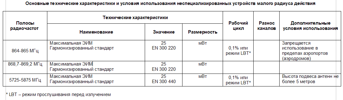
Here you can see that in line 2 of the table are very tempting data. Like that, there is no limit on duty cycle. Practical experience shows that this particular frequency interval is simply dirtied. At least in Moscow. Therefore, although it is tempting to use the frequency window on line 2, it is better to pay attention to the previous line. There are strict restrictions here, but here you can work with data collection systems that are transmitted rarely and quickly (data in small chunks of a few bytes at most).
Also note that in the same document in Appendix 14 the following is given:

This table refers to wireless audio devices such as pop microphones.
One GKRCH knows why “non-specialized devices” in this range cannot be used within aerodromes, and radio microphones are possible.
But one way or another, but if in this particular place the use of audio devices with a radio channel is assumed, then mutual interference with the data acquisition system is possible. This should be considered.
I note that the range is much less "polluted."
It should be taken into account that burglar alarm devices are operating at neighboring frequencies. Also, if you have a cell tower at your side, this factor may also affect your work.
In budget devices it is very difficult to implement a good rejection of neighboring ranges, and even more so, to filter out a specific narrow strip, selected from the entire possible range.
In the absence of a spectrum analyzer in this situation, the only possible solution is the trial and error method for finding a more or less “crap” window. Unfortunately.
It should also be borne in mind that when using chips from the CC1101 series, the intermediate frequency in them does not exceed several hundred kHz. Therefore, we must also look at what is happening on the mirror channel.
Frequency setting accuracy
Often when you first start the created devices to receive / transmit, an inexperienced engineer faces a lack of communication even at very small distances with correctly set parameters. The reason is the scatter of the ratings of the quartz resonators and, accordingly, the reference frequencies of the synthesizers.
In the usual retail (and not only) "radio store", quartz resonators are usually available with an installation accuracy of no higher than 10 ppm. Those. at 26 MHz, which is standard for the CC1101, the frequency spread is 260 Hz. It seems to be a bit. However, for a good range and high sensitivity with a low volume of transmitted data, it is very tempting to use a speed of 1.2 kbaud (or lower) with the corresponding band, which is comparable to the deviation of the frequency setting of the quartz resonator. This leads to demodulation errors in modes like FSK or MSK. Accordingly, incorrect reception of the header leads to loss of synchronization and complete loss of the data packet.
Practice shows that the use of narrow bands is impossible when using conventional quartz resonators in the mode of frequency modulation. In modes like ASK / OOK this is less significant, but in this mode the communication range is much smaller.
It requires either the use of high-precision resonators, or apply some technology that allows to eliminate the consequences of the spread of the driving frequencies.
In the future, the simplest program will be given, which makes it possible to set the operating frequency with a given accuracy using the budget frequency meter. However, the program is good at using single devices. In the case of at least some seriality method is very cumbersome.
The simplest and most reliable way to set the correct reference frequency is to use highly stable quartz oscillators, for example, from Taitien [2]. These generators are relatively cheap, stable and have precision adjustment, if you really need this. They can even be used as reference in systems with OFDM.
When using generators with a clipped sinusoidal signal at the output, it is fed to pin 8 of CC1101 using the simple circuit shown in the following figure.
Here, the DD2 chip is used as an amplifier-shaper.
Do not pay attention to the frequency of 20 MHz: taken from another device.

Antenna
The documentation on the CC1101 gives examples of the implementation of matching circuits with standard antennas with an impedance of 50 ohms. There are other solutions on the Texas Instrument website, including printed antenna documentation that can be carried to the production of printed circuit boards.
Nevertheless, experience shows that due to the variation in the parameters of materials of printed circuit boards, installation features and other factors, it is almost impossible to create a board topology such that the antenna from Application Notes has exactly the parameters that are expected from it, with good coordination, t. e. radiation efficiency and sensitivity were high.
Therefore, it is necessary to use antennas that are part of the board's topology with great care. And you need to be prepared for the unexpected.
STMicroelectronics manufactures baluns of type BAL-CC1101-01D3. They are somewhat difficult to mount, but they give excellent predictable results. Coordination with any antenna with an impedance of 50 ohms is almost perfect, which allows you to safely use ready-made commercial antennas.
Very good results are achieved by combining the above balun with an ANT 868 SP type antenna from Linx Technologies. One of the results will be described later.
Conclusion on the radio path
This chapter describes some of the difficulties that a radio engineer faces when building a peer-to-peer network based on a chip of class CC1101. The presented methods allow to solve problems using budget methods.
In the process of writing this text, there were so many subtleties that I would like to describe that it can pull on a little work :-). So I decided to publish material chapter by chapter at a time. Only after complete exhaustion of questions and clarifications on a specific chapter will the following be published.
Introduction
So, you need to build a simple network, the form of which is presented in the following figure. It is desirable to build a network without using expensive spectrum analyzers and other equipment for the analysis of radio engineering circuits. It is also desirable that the software is sufficiently transparent and as simple as possible.
It is assumed that the D0 ... Di ... DN sensors are self-powered, and the data acquisition device is connected to the mains or some other source with respect to unlimited power.
In this work, an attempt is made (regular :)) to systematize approaches to building such a simple peer-to-peer network for collecting data from autonomous sensors from the point of view of a radio engineer who has only basic knowledge of programming.
')
An attempt was made to create devices based on purchased products of this class, which can be simply connected as a designer, without using expensive devices.
Chapter 1. Some radio problems and solutions
Building a system from the figure above begins with a radio channel. If the radio channel is bad, then everything else, if it will work, it does not matter. And the software will deal with the lion's share of the time to fix radio channel defects. To avoid this, the following aspects should be taken into account.
Range
Let's start with the operating frequency range. Open the document [1]. The following is displayed in Appendix 10:
Here you can see that in line 2 of the table are very tempting data. Like that, there is no limit on duty cycle. Practical experience shows that this particular frequency interval is simply dirtied. At least in Moscow. Therefore, although it is tempting to use the frequency window on line 2, it is better to pay attention to the previous line. There are strict restrictions here, but here you can work with data collection systems that are transmitted rarely and quickly (data in small chunks of a few bytes at most).
Also note that in the same document in Appendix 14 the following is given:
This table refers to wireless audio devices such as pop microphones.
One GKRCH knows why “non-specialized devices” in this range cannot be used within aerodromes, and radio microphones are possible.
But one way or another, but if in this particular place the use of audio devices with a radio channel is assumed, then mutual interference with the data acquisition system is possible. This should be considered.
I note that the range is much less "polluted."
It should be taken into account that burglar alarm devices are operating at neighboring frequencies. Also, if you have a cell tower at your side, this factor may also affect your work.
In budget devices it is very difficult to implement a good rejection of neighboring ranges, and even more so, to filter out a specific narrow strip, selected from the entire possible range.
In the absence of a spectrum analyzer in this situation, the only possible solution is the trial and error method for finding a more or less “crap” window. Unfortunately.
It should also be borne in mind that when using chips from the CC1101 series, the intermediate frequency in them does not exceed several hundred kHz. Therefore, we must also look at what is happening on the mirror channel.
Frequency setting accuracy
Often when you first start the created devices to receive / transmit, an inexperienced engineer faces a lack of communication even at very small distances with correctly set parameters. The reason is the scatter of the ratings of the quartz resonators and, accordingly, the reference frequencies of the synthesizers.
In the usual retail (and not only) "radio store", quartz resonators are usually available with an installation accuracy of no higher than 10 ppm. Those. at 26 MHz, which is standard for the CC1101, the frequency spread is 260 Hz. It seems to be a bit. However, for a good range and high sensitivity with a low volume of transmitted data, it is very tempting to use a speed of 1.2 kbaud (or lower) with the corresponding band, which is comparable to the deviation of the frequency setting of the quartz resonator. This leads to demodulation errors in modes like FSK or MSK. Accordingly, incorrect reception of the header leads to loss of synchronization and complete loss of the data packet.
Practice shows that the use of narrow bands is impossible when using conventional quartz resonators in the mode of frequency modulation. In modes like ASK / OOK this is less significant, but in this mode the communication range is much smaller.
It requires either the use of high-precision resonators, or apply some technology that allows to eliminate the consequences of the spread of the driving frequencies.
In the future, the simplest program will be given, which makes it possible to set the operating frequency with a given accuracy using the budget frequency meter. However, the program is good at using single devices. In the case of at least some seriality method is very cumbersome.
The simplest and most reliable way to set the correct reference frequency is to use highly stable quartz oscillators, for example, from Taitien [2]. These generators are relatively cheap, stable and have precision adjustment, if you really need this. They can even be used as reference in systems with OFDM.
When using generators with a clipped sinusoidal signal at the output, it is fed to pin 8 of CC1101 using the simple circuit shown in the following figure.
Here, the DD2 chip is used as an amplifier-shaper.
Do not pay attention to the frequency of 20 MHz: taken from another device.
Antenna
The documentation on the CC1101 gives examples of the implementation of matching circuits with standard antennas with an impedance of 50 ohms. There are other solutions on the Texas Instrument website, including printed antenna documentation that can be carried to the production of printed circuit boards.
Nevertheless, experience shows that due to the variation in the parameters of materials of printed circuit boards, installation features and other factors, it is almost impossible to create a board topology such that the antenna from Application Notes has exactly the parameters that are expected from it, with good coordination, t. e. radiation efficiency and sensitivity were high.
Therefore, it is necessary to use antennas that are part of the board's topology with great care. And you need to be prepared for the unexpected.
STMicroelectronics manufactures baluns of type BAL-CC1101-01D3. They are somewhat difficult to mount, but they give excellent predictable results. Coordination with any antenna with an impedance of 50 ohms is almost perfect, which allows you to safely use ready-made commercial antennas.
Very good results are achieved by combining the above balun with an ANT 868 SP type antenna from Linx Technologies. One of the results will be described later.
Conclusion on the radio path
This chapter describes some of the difficulties that a radio engineer faces when building a peer-to-peer network based on a chip of class CC1101. The presented methods allow to solve problems using budget methods.
Links
[1] Decision of the State Committee on Radio Frequency Act No. 08-24-01-001 dated April 28, 2008
[2] 3.2 x 2.5 mm SMD Voltage Controlled Temperature Compensated Crystal Oscillator ( http://www.taitien.com/wp-content/uploads/2015/12/XO-0076_TX.pdf )
[3] CC1101 under the control of a PIC controller or building a peer-to-peer network for a radio engineer. Part 1
[2] 3.2 x 2.5 mm SMD Voltage Controlled Temperature Compensated Crystal Oscillator ( http://www.taitien.com/wp-content/uploads/2015/12/XO-0076_TX.pdf )
[3] CC1101 under the control of a PIC controller or building a peer-to-peer network for a radio engineer. Part 1
Source: https://habr.com/ru/post/348840/
All Articles