BLE400 board and development for nRF51822
For development under the nRF51822 microcontroller, there are several kits from Nordic Semiconductor, all of them are quite expensive, but they provide the possibility of convenient operation without fussing with programmers. At the same time, Chinese manufacturers can detect boards that make it easier to debug controllers for ridiculous money. The article is devoted to working with a clone of the board from Waveshare which is sold under the name BLE400 .
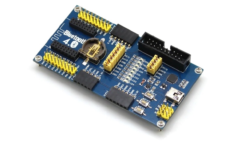
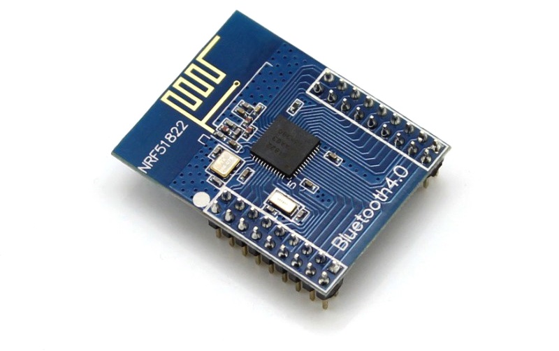
The board is designed for use with NRF51822 modules, which are a decoupled chip with an antenna and a pair of quartz resonators. The cost of a set of board and module is about $ 20.
The BLE400 contains onboard a USB port and a USB-UART converter based on the CP2102 chip with outputted RX, TX, CTS and RTS signals. At the circuit level, it is partially compatible with the PCA10001, a debugging board from Nordic, a pair of LEDs and two buttons are connected to the same ports, for fans of the LED to flash, this will make life a little easier. Unfortunately, the board does not know how to play the role of the nRF51822 programmer, although there is a firmware that allows you to work with the Arduino-type loader on the network. I will quickly list what exactly is built into the board, in part it will be a translation of the documentation from here .
')
Initially, the module is flashed with the code for working with nRF Toolbox for BLE from Nordic Semiconductor, this is enough to check its operation. We connect the board to the PC, install the drivers for the CP2102 and connect to the board using the terminal. I used PuTTY, the parameters of the port: speed 38400 data bit 8, Stop bit one, flow control software.
We connect, in the terminal we drive in the English character Y or y, we receive in response the command Start ... - the controller works.
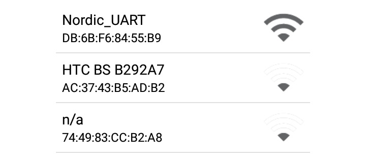
Now it is available in the list of BLE compatible devices on the phone with the name Nordic_UART. By installing the application for Android, you can play with the transfer of characters through a virtual Bluetooth terminal and test the UART emulation.
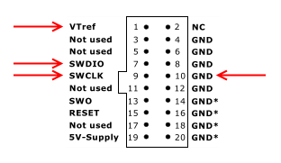
Go to the programming. We still need a programmer, the original from Segger will be a little expensive, but thanks to the motorists there are enough J-link ARM v8 clones on the market, they cost about $ 15 and for our purposes there are more than enough. We assume that the drivers for the programmer (for example, J-Link Software v4.52b +) are already installed. We connect to the board with standard JTAG cable from the programmer or four wires, it’s enough to connect VTref, GND, SWDIO and SWCLK.
To check the connection, run JLink.exe and get information about the installed chip
We need the following software
To get the Lite version of Keil MDK-ARM registration is required, the rest is available for download as follows. nRFgo Studio version 1.21.2 I never started under Windows 10, but the younger version 1.15.1 works. The latest version of the SDK with support for the pca10001 board is version 6, download here . After installing the SDK, the
You can program the board not only through the J-Link Commander console, but also via nRFgo Studio, through it we can clear the chip or pour the SoftDevice to work with Bluetooth. This is done from the menu nRF51 Programming. The core of the BLE stack is already embedded in the chip. You can clear it through the menu item Erase all.

The next task is to flash the LEDs carefully soldered on the board. As mentioned earlier, the LEDs and buttons are compatible with the pca10001 board from Nordic, so we use an example from there, open it in the folder with Keil4
We compile the project by pressing F7 and flash through the menu Flash-> Download. My default was not stitched because of the default JTAG fill rate of 2000 kHz. You can fix it from the menu Option for target -> Debug -> Setting. After replacing with 100 kHz, everything worked successfully. LEDs LED0 and LED1 successfully blink, the microcontroller is working. If you still can not download, you can try to flash HEX from the

The LEDs are great, but we still need Bluetooth, an example for the work lies in the
Initially, the header files for version 7.0.0 come with the SDK, but this version of the kernel did not start with me. Theoretically, any version of the stack should work, versions v6, v7, v8 are available for download. With examples from the SDK, the seventh and eighth versions of the stack did not work for me, I stopped at 6.2.1.
Download the kernel , unpack it into a convenient folder for you, for example, Cores
SoftDevice needs to be flashed. To do this, we use nRFgo Studio, select the nRF51 Programming item from the Device Manager menu and make sure that the programmer does not fall off. In the Program SoftDevice tab, select the file with the core

We press the Program button. The memory card of the device now looks like this:

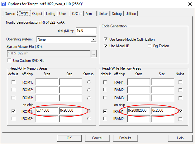
The RAM became less by 8kb, and the first 80 kilobytes of the permanent memory occupied the core. Change Target to target with s110 stack, choose from the menu nrf51822_xxaa_s110 (256K)

To build an example with a flashing LED, when SoftCore is installed, it is necessary to introduce corrections into the memory card, this is done from the menu Options for Target - Target. The base address changes to
Since we do not have to wipe the kernel when casting the sketch, we change the settings of the programmer. This is done from the Options for Target menu - Debug, the Setting button.

We assemble the project and fill it into the controller, if the core is installed correctly, we will get the same blinking LEDs. It's time to fill in the firmware imitating iBeacon, open the project from the folder
If everything passed successfully, LED0 will glow, this is an indicator that packets are being sent. Install an application that can see iBeacon on your Android or iOS device, I downloaded
Beacon Scanner . The device UUID matches the constant APP_BEACON_UUID in the source code, so this is our beacon.

In principle, this information is sufficient for a quick and very inexpensive start of work with BLE. On the downside, this is support for outdated Keil 4 and unstable operation of the programmer at frequencies of 100 kHz and above. If the development environment gives a boot error, reduce the access speed to 50 kHz or even less. Sometimes the programmer falls off and you can bring it back to life only by running JLink.exe, perhaps this is due to the fact that it is a clone of the original.
The board is designed for use with NRF51822 modules, which are a decoupled chip with an antenna and a pair of quartz resonators. The cost of a set of board and module is about $ 20.
The BLE400 contains onboard a USB port and a USB-UART converter based on the CP2102 chip with outputted RX, TX, CTS and RTS signals. At the circuit level, it is partially compatible with the PCA10001, a debugging board from Nordic, a pair of LEDs and two buttons are connected to the same ports, for fans of the LED to flash, this will make life a little easier. Unfortunately, the board does not know how to play the role of the nRF51822 programmer, although there is a firmware that allows you to work with the Arduino-type loader on the network. I will quickly list what exactly is built into the board, in part it will be a translation of the documentation from here .
')
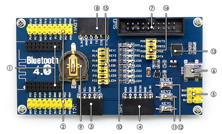
- The seat for the NRF51822 module is missing, there is no key, the module can be inserted incorrectly, but then it will close the battery and the antenna will be the opposite
- It duplicates the pins of the NRF51822 module, convenient for prototyping
- An I2C interface for easy connection, duplicates the corresponding signals from the SDA comb - P0.00 SCL - P0.01 SMBA - P0.02 and power, ready-made modules from Waveshare can be used
- SPI interface, MISO signals are output - P0.23 MOSI - P0.24 SCK - P0.25 NSS - P0.30
- Power, when connected via USB, you can use the power of 5 volts, from the battery and the programmer will only be available 3.3. The power supply is done on RT9193 with a maximum current of 300mA, the module itself consumes a maximum of 2mA and is ready to load a maximum of 3 pins at 5 mA or 1 pin with a current of 15mA. Total 250 mA per periphery in stock
- Mini-USB socket for power or PC connection. 5 volt port is directly connected to the power comb
- Simplified SWD interface for programming. Power 3.3v, SWDIO and SWCLK
- Duplicated UART, it is also connected to the CP2102 and is available for monitoring on a PC through a virtual COM port. RX - P0.05 TX - P0.06 CTS - P0.07 RTS - P0.12
- Battery size CR1225, useful for offline testing
- A set of LEDs connected to P0.18 P0.19 P0.20 P0.21 P0.22. Lit when a logical unit is applied. Here you can see the activity of the signals RX, TX and SPD
- Two buttons connected to ports P0.16 and P0.17. When pressed, gives a logical zero.
- Reset button Resets CP2102 and NRF51822 to null the SWDIO signal
- Virtual COM Port Controller on CP2102, DTR and DSR are not soldered
- Jumpers to disable the UART interface from the CP2102
- Jumpers to turn off LEDs and buttons
Initially, the module is flashed with the code for working with nRF Toolbox for BLE from Nordic Semiconductor, this is enough to check its operation. We connect the board to the PC, install the drivers for the CP2102 and connect to the board using the terminal. I used PuTTY, the parameters of the port: speed 38400 data bit 8, Stop bit one, flow control software.
We connect, in the terminal we drive in the English character Y or y, we receive in response the command Start ... - the controller works.
Now it is available in the list of BLE compatible devices on the phone with the name Nordic_UART. By installing the application for Android, you can play with the transfer of characters through a virtual Bluetooth terminal and test the UART emulation.
Go to the programming. We still need a programmer, the original from Segger will be a little expensive, but thanks to the motorists there are enough J-link ARM v8 clones on the market, they cost about $ 15 and for our purposes there are more than enough. We assume that the drivers for the programmer (for example, J-Link Software v4.52b +) are already installed. We connect to the board with standard JTAG cable from the programmer or four wires, it’s enough to connect VTref, GND, SWDIO and SWCLK.
To check the connection, run JLink.exe and get information about the installed chip
SEGGER J-Link Commander V4.74b ('?' for help) Compiled Aug 19 2013 23:26:57 DLL version V4.74b, compiled Aug 19 2013 23:26:44 Firmware: J-Link ARM V8 compiled Nov 28 2014 13:44:46 Hardware: V8.00 S/N: 20091135 Feature(s): RDI,FlashDL,FlashBP,JFlash,GDBFull VTarget = 3.293V Info: Found SWD-DP with ID 0x0BB11477 Info: FPUnit: 4 code (BP) slots and 0 literal slots Info: Found Cortex-M0 r0p0, Little endian. Found 1 JTAG device, Total IRLen = 4: Cortex-M0 identified. JTAG speed: 100 kHz We need the following software
To get the Lite version of Keil MDK-ARM registration is required, the rest is available for download as follows. nRFgo Studio version 1.21.2 I never started under Windows 10, but the younger version 1.15.1 works. The latest version of the SDK with support for the pca10001 board is version 6, download here . After installing the SDK, the
\ARM\Device\Nordic\nrf51822 containing all the necessary files will appear in the folder where Keil is installed. The examples are designed to use Keil version 4, the project file has the extension uvproj, unlike Keil 5 where the extension is uvprojx. Actually, we use Keil 4 in order not to get confused in the configuration files and compatibility examples.You can program the board not only through the J-Link Commander console, but also via nRFgo Studio, through it we can clear the chip or pour the SoftDevice to work with Bluetooth. This is done from the menu nRF51 Programming. The core of the BLE stack is already embedded in the chip. You can clear it through the menu item Erase all.
The next task is to flash the LEDs carefully soldered on the board. As mentioned earlier, the LEDs and buttons are compatible with the pca10001 board from Nordic, so we use an example from there, open it in the folder with Keil4
\ARM\Device\Nordic\nrf51822\Board\pca10001\blinky_example\arm\ project file blinky.uvproj.We compile the project by pressing F7 and flash through the menu Flash-> Download. My default was not stitched because of the default JTAG fill rate of 2000 kHz. You can fix it from the menu Option for target -> Debug -> Setting. After replacing with 100 kHz, everything worked successfully. LEDs LED0 and LED1 successfully blink, the microcontroller is working. If you still can not download, you can try to flash HEX from the
_build blinky_arm.hex folder using nRFgo Studio or from the console of the J-Link programmer. But first you have to convince you that J-Link programmer is selected in Keil settings.The LEDs are great, but we still need Bluetooth, an example for the work lies in the
\ARM\Device\Nordic\nrf51822\Board\pca10001\s110\ble_app_beacon . This is an iBeacon implementation, for us it is interesting to work with the Nordic BLE software stack. The example is designed for the s110 version of the stack, the simplest one in terms of its capabilities, but this is quite enough to demonstrate its efficiency. The kernel must be downloaded separately and there are a lot of versions of it, and the version of the headers should correlate with the version of the kernel. You can download kernels via the link in the SoftDevices section.Initially, the header files for version 7.0.0 come with the SDK, but this version of the kernel did not start with me. Theoretically, any version of the stack should work, versions v6, v7, v8 are available for download. With examples from the SDK, the seventh and eighth versions of the stack did not work for me, I stopped at 6.2.1.
Download the kernel , unpack it into a convenient folder for you, for example, Cores
ARM\Device\Nordic\nrf51822\Cores\6.2.1 . We clear the already existing \ARM\Device\Nordic\nrf51822\Include\s110 and copy the header files from the include folder of the unpacked kernel into it.SoftDevice needs to be flashed. To do this, we use nRFgo Studio, select the nRF51 Programming item from the Device Manager menu and make sure that the programmer does not fall off. In the Program SoftDevice tab, select the file with the core
\ARM\Device\Nordic\nrf51822\Cores\6.2.1\s110_nrf51822_6.2.1_softdevice.hex . If the file of the correct format below will indicate the occupied capacity, for this version of SoftDevice is equal to 80kb.We press the Program button. The memory card of the device now looks like this:
The RAM became less by 8kb, and the first 80 kilobytes of the permanent memory occupied the core. Change Target to target with s110 stack, choose from the menu nrf51822_xxaa_s110 (256K)
To build an example with a flashing LED, when SoftCore is installed, it is necessary to introduce corrections into the memory card, this is done from the menu Options for Target - Target. The base address changes to
CODE_R1_BASE = 0x00014000 , and the free memory starts at address 0x20002000.Since we do not have to wipe the kernel when casting the sketch, we change the settings of the programmer. This is done from the Options for Target menu - Debug, the Setting button.
We assemble the project and fill it into the controller, if the core is installed correctly, we will get the same blinking LEDs. It's time to fill in the firmware imitating iBeacon, open the project from the folder
\ARM\Device\Nordic\nrf51822\Board\pca10001\s110\ble_app_beacon . We change the memory card by analogy with the flashing LED, collect and fill in the device.If everything passed successfully, LED0 will glow, this is an indicator that packets are being sent. Install an application that can see iBeacon on your Android or iOS device, I downloaded
Beacon Scanner . The device UUID matches the constant APP_BEACON_UUID in the source code, so this is our beacon.
In principle, this information is sufficient for a quick and very inexpensive start of work with BLE. On the downside, this is support for outdated Keil 4 and unstable operation of the programmer at frequencies of 100 kHz and above. If the development environment gives a boot error, reduce the access speed to 50 kHz or even less. Sometimes the programmer falls off and you can bring it back to life only by running JLink.exe, perhaps this is due to the fact that it is a clone of the original.
Source: https://habr.com/ru/post/348684/
All Articles