Creating parametric database objects in nanoCAD Mechanics (Part 3)
Part 3. Creating performances. Assembly dependencies

In the previous part, we familiarized with the basic toolkit of the Object Master nanoCAD Mechanics for creating a parametric object and reviewed the process of setting parameters for the created base element.
Obviously, the greatest effect from the parameterization of objects will be obtained when creating executions of objects, as well as specifying external dependencies with other elements of the base for designing intelligent assemblies that are controlled through the parameters of objects.
')
In this part, we will use the nanoCAD Mechanics toolkit, designed to create full-fledged parametric objects and manage assembly dependencies.
In the Custom items folder folder, right-click (RMB) on the new object Puck_10H205-00-414-01 and select Open in the Object Wizard from the context menu (Fig. 1).
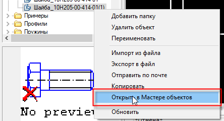
Fig. one
On the Execution branch, click RMB and select Add execution from the context menu (Fig. 2). Next, create a view by analogy with the first execution. Right-click on the new version that appears in the right part of the Object Wizard window, call the context menu and select parametric recognition. As a sketch, we use the same geometry as for the first performance.

Fig. 2
In this case, we confine ourselves to only one type (see part 1, “Preparing the geometry of an object. Creating an element of the base” , Fig. 5).
Now that the geometry of the object for a new version has been added, we will make some changes to the program code of the object.
For the convenience of navigating through the script, open the Methods branch and then the Event Handler . A list of all the main functions used in the script. To create a new performance, we need handlers:
ActHeader, OnInitialization, OnMakeParameters, OnDialog.
In ActHeader, the Protected section, you must declare the parameters (Fig. 3):
(seted, B1, B2, b1, b2);

Fig. 3
In OnInitialization, instead of B and b, we assign the values to the new parameters entered (Fig. 4):
B1 = 6; B2 = 4; b1 = 3; b2 = 2

Fig. four
In OnMakeParameters we add the following construction, passing to the performances certain values of the variables (Fig. 5):
if (strDesignName == "Implementation1") {b = b1};
if (strDesignName == "Implementation2") {b = b2};
if (strDesignName == "Implementation1") {B = B1};
if (strDesignName == "Implementation2") {B = B2};

Fig. five
To display all the performances in the insert dialog, add to OnDialog (Fig. 6):
VIDS, strDesignName, "All",

Fig. 6
Save the changes and close the Object Wizard . Check the script. Insert the modified puck from the database of objects into the model space. Now, in the appeared dialog of the insert dialog two performances will be available (Fig. 7).

Fig. 7
Select the second version, click OK . The width of the washer will change in accordance with the parameter values specified in OnInitialization .
Now, to use a new object in a parametric assembly, you need to create external dependencies. Such dependencies are described in the OnConnect handler . In the basic example, the Washer (the order of connecting this object to the database is presented in Part 2: "Working with the object code. Script wizard" ) the main build dependencies are already set. Let's open this object in the Object Wizard , copy a part of the script describing the OnConnect function, and paste this code into a new puck (Fig. 8).
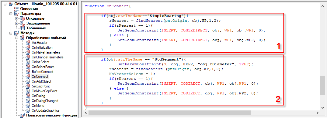
Fig. eight
The first part of this script creates an assembly dependence of the element to be added and the bearing — in such a way that when a bearing is specified, the working plane of the element (in this case, the end face of the washer) will coincide with the nearest plane of the bearing. On which side of the mid-plane the bearing is selected, the puck will be displayed with this.
The second part describes the dependence of the shaft segment and the inner (seating) surface of the washer, the diameter of which is indicated by the variable "d" . Using the function of dynamic parameter selection (button in the insert object dialog
 ), after specifying the surface, you can move the object to be installed to any point along the axis.
After inserting the code into a new object, go up the Event Handlers branch in BeforeConnect . This handler allows you to display a prompt message about the necessary actions after adding an object to the model space. We write to it after ResetLastConstraint (); following expression:
if (rPart == 0) {strPromt = "Select a bearing, or a shaft step"; }
In ActHeader, we add a variable NSelect with a value of 2, which determines the number of requests for objects when inserting - if necessary, this will allow controlling the landing diameter of the washer by selecting the desired shaft diameter, after specifying the bearing.
Save the changes and close the Object Wizard .
To test the resulting object, take an uncomplicated assembly created from the standard elements of the nanoCAD Mechanics database. Download the assembly file at the link: goo.gl/g9Eks8
Open the assembly and add a new object to it. An informational message appears , which was registered in the BeforeConnect handler. In the command line, the program will prompt: "Select the insertion point . " It is necessary to indicate the bearing in such a way that the washer is to the left of it (Fig. 9).

Fig. 9
Click the mouse to fix the position. By a second click, select the shaft to which the washer is installed, to adjust the inner diameter. The insert dialog window, which is already familiar to us, will appear, in which you can change the values of parameters and select views, as well as change performances. Select the second performance, click Apply . The width of the washer will change in accordance with the specified parameters, while maintaining the dependencies with the bearing and the shaft (Fig. 10).

Fig. ten
We fix the changes by pressing the OK button . In the future, if you need to change the performance, you can enter the insert dialog by double clicking on the object.
We now turn to dependency management.
The considered node is a parametric assembly - all objects are connected by certain dependencies, and when, say, the dimensions of the bearings change, the sizes of all interrelated parts will change.
Using the Manage Dependencies command, you can create or delete various dependencies between the parameters of various database objects, including custom ones.
The standard database elements used in this example already have all the necessary dependencies. For a user object, such dependencies have not yet been defined, but adding them will not be difficult. As an example, we will create the relationship between the diameters of the washer and the glass, which will allow us to avoid errors associated with the overlapping of parts with a significant decrease in the external diameters of the bearings and, as a result, a decrease in the size of the glass.
To launch the command in the menu Mechanics → Standard we call the Manage Dependencies command (Fig. 11).

Fig. eleven
In the window that opens, click on the Child object icon and select the puck, then select Glass as the parent object. We open the branches of the parameters of both objects and double-click in the washer the diameter D , and in the glass the diameter Dv . Parameters will be added below in the input field. In the right side of the equation, you can enter mathematical expressions. Add "-0.25" after the parameter designation, thus ensuring the gap between the parts. Click the Save dependencies button and close the window by clicking the OK button (Fig. 12). Changes made will be displayed on the screen.

Fig. 12
To check the operation of the created dependency, we change the parameters of the bearings. To do this, enter the object insertion dialog and change the outer diameter from 85 to 75 or 100 , click OK . The dimensions of the bearings and, as a result, the diameter of the glass will change, but the diameter of the hole of the glass will remain the same, the specified gap size will remain (Figure 13).

Fig. 13
Thus, you can link any parameters of different parts, as well as make changes to the created dependencies using mathematical expressions.
In conclusion, for clarity and simplification of the visual search, through the functionality of the Object Wizard, you can add a picture or a 3D model to the preview window of the object.
To do this, being in the Object Wizard , right-click on the topmost element of the tree and select one of the first two options from the context menu.
In our case, a 3D model of the puck was prepared (download which can be found here: goo.gl/cVo2p7 ), therefore we select Set a preview image on the object (Fig. 14). In this case, the corresponding model should be open in the model space. Click on the model, press Enter - the model of the washer will be displayed in the preview window.
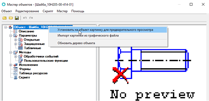
Fig. 14
Save and close the Object Wizard . To display the model in the preview window, click the Refresh button.
 on the toolbar tab of the Base items . To rotate the model in the preview window, hover the cursor on it and move it with the mouse button held down (fig. 15).
Fig. 15
So, we looked at some of the capabilities of nanoCAD Mechanics related to the creation and working with parametric objects. Noted the nuances of preparing the geometry for creating a parametric element and adding a new base element, learned how to include an imported file. We analyzed the ways of parametrizing the elements of the base: with the help of the Script Wizard and using similar objects. We have mastered the process of creating external dependencies of a user part for working with parametric assemblies.
Of course, parametrization is in a certain sense a departure from traditional methods, but if properly applied, it can significantly speed up the design process and improve its quality.
As a result, parametric modeling slowly but surely acquires the rights of a new design standard.
As for the program nanoCAD Mechanics , the improvement of parametric modeling tools has already become one of the main vectors of its development.
Source: https://habr.com/ru/post/348642/
All Articles