Developing a PCI device driver for Linux
In this article, I look at the process of writing a simple PCI device driver under Linux OS. The device of the PCI software model, the writing of the driver itself, the user test program and the launch of the entire system will be briefly studied.
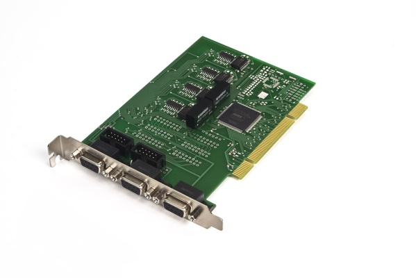
The interface of LIR940 / 941 displacement sensors will be presented as an experimental. This device, domestically produced, provides connection to up to 4 encoders using the serial SSI protocol over the RS-422 physical interface.
Today, the PCI bus (and its newer version, PCI Express) is a standard interface for connecting a wide range of additional equipment to modern computers and this bus does not need a special presentation.
It is not uncommon in the form of a PCI adapter that various specialized input / output interfaces are implemented to connect at least specialized external equipment.
Also, there are still not rare situations when a hardware manufacturer provides a driver only for Windows OC.
')
LIR941 was acquired by the organization in which I work to obtain data from high-precision absolute displacement sensors. When there was a question about working under Linux, it turned out that the manufacturer does not provide anything for this OS. There was also nothing in the network, which, incidentally, is normal for such a rare and specialized device.
On the board itself, there is an Altera FPGA, which implements the entire interaction logic, as well as several (from 2 to 4) RS-422 interfaces with galvanic isolation.
Typically, in such a situation, developers go the way of reverse engineering, trying to figure out how the Windows driver works.
Morally preparing for this entertainment, I decided to start by trying the easiest and most direct way - I wrote the request directly to the equipment manufacturer.
I asked if they could provide any documentation or specification for their device, so that I could develop an open source driver for Linux. To my surprise, the manufacturer went to the meeting, they answered me very quickly and sent all the necessary documentation!
PCI bus
Before proceeding to the development of the actual driver, I propose to consider how the PCI software model works and how it interacts with the device.
A small note about PCI and PCI Express.The PCI bus allows you to connect at the same time a large number of devices and often consists of several physical buses connected to each other through special “bridges” - the PCI Bridge. Each bus has its own number, devices on the bus are also assigned a unique number. Also, each device can be multifunctional, as if divided into separate devices that implement some separate functions, each such function is assigned its own number in the same way.
Despite the fact that the hardware is two different interfaces - they both use the same software model, so from the point of view of the developer there is no particular difference and the driver will work the same way.
Thus, the system "path" to the specific functionality of the device looks like this:
<pci bus number> <device number> <function number>.
To see which devices are connected to the PCI bus on Linux, just run the lspci command.
The output may be unexpectedly long, since in addition to devices directly physically connected via pci / pci express slots (such as a video adapter), there are many system devices that are soldered (or included in a chipset chipset device) on the motherboard.
The first column of this conclusion, consisting of numbers, is precisely the set of identifiers discussed above.
For example:
$ lspci 01:00.0 VGA compatible controller: NVIDIA Corporation GT215 [GeForce GT 240] This output means that the NVIDIA GT 240 video adapter is on PCI bus 01, the device number is 00 and its only function number is also 0.
It should also be added that each PCI device has a set of two unique identifiers - Vendor ID and Product ID, which allows drivers to uniquely identify devices and work with them correctly.
The issuance of unique Vendor ID for hardware manufacturers engaged in a special consortium - PCI-SIG .
To see these identifiers it is enough to run lspci with the -nn keys:
$ lspci -nn 01:00.0 VGA compatible controller [0300]: NVIDIA Corporation GT215 [GeForce GT 240] [10de:0ca3] Where 10de is the manufacturer's identifier, NVIDIA Corporation, and 0ca3 is the identifier of the specific hardware.
Find out who is who can use special sites, such as The PCI ID Repository
Reading service information and configuration of a PCI device is carried out through a set of configuration registers. Each device must provide a standard set of such registers, which will be discussed later.
The registers are mapped into the computer’s RAM at boot time and the operating system kernel associates with the device a special data structure - pci_dev, and also provides a set of functions for reading and writing.
In addition to the PCI configuration registers, devices can have up to 6 data input / output channels. Each channel is also displayed in RAM at a certain address assigned by the OS kernel.
Read-write operations of this memory area, with certain parameters of block size and offset, lead directly to write-read to the device.
It turns out that to write a PCI driver, you need to know what configuration registers the device uses, as well as what offsets (and what exactly) you need to write / read. In my case, the manufacturer provided all the necessary information.
PCI configuration space
The first 64 bytes are standardized and must be provided by all devices, whether they are required or not.
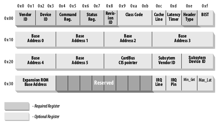
The picture shows the registers that are mandatory, they must always contain any meaningful values, the rest may contain zeros, if this is not required in this case.
The byte order in all PCI registers is little-endian, this should be considered if driver development is carried out for an architecture with a different order.Let's see what some of the registers are.
VendorID and ProductID are registers already known to us, in which the manufacturer and equipment identifiers are stored. Each of the registers takes 2 bytes.
Command - this register defines some features of a PCI device, for example, it allows or denies access to memory.
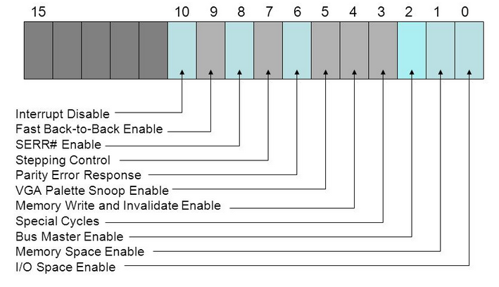
The initialization of these bits is handled by the operating system.
Status - bits of this register store information about various PCI bus events.
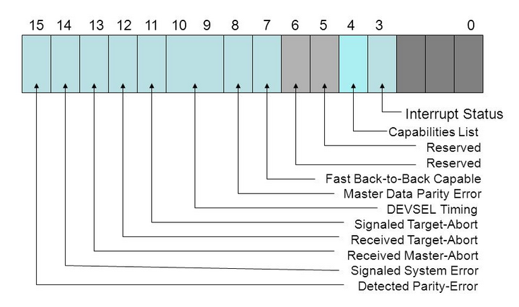
These values are set by the equipment; in my case, only bits 9, 10 were configured, which determine the board response time.
Revision ID - number, revision of a specific board. Useful when there are several revisions of the device and differences need to be considered in the driver code.
Class Code is a “magic” number that displays the class of the device, for example: Network Controller, Display Controller, etc. The list of existing codes can be found here .
Base Address Registers - these registers, in the amount of 6 pieces, are used to determine how and how much memory is allocated to the device for input / output procedures. This register is used by the pci subsystem of the kernel and is usually not of interest to driver developers.
Now you can go to programming and try to read these registers and get access to the I / O memory.
Kernel module development
As many probably know, the entry and exit points to the Linux kernel module are special __init and __exit functions.
We define these functions and execute the procedure for registering our driver by calling the special function pci_register_driver (struct pci_driver * drv), as well as the unloading procedure using pci_unregister_driver (struct pci_driver * drv).
#include <linux/init.h> #include <linux/module.h> #include <linux/pci.h> static int __init mypci_driver_init(void) { return pci_register_driver(&my_driver); } static void __exit mypci_driver_exit(void) { pci_unregister_driver(&my_driver); } module_init(mypci_driver_init); module_exit(mypci_driver_exit); The argument of the register and unregister functions is the pci_driver structure that needs to be initialized first, let's do it at the very beginning, declaring the structure static.
static struct pci_driver my_driver = { .name = "my_pci_driver", .id_table = my_driver_id_table, .probe = my_driver_probe, .remove = my_driver_remove }; The structure fields that we initialize:
name is the unique name of the driver that will be used by the kernel in / sys / bus / pci / drivers
id_table is a table of the Vendor ID and Product ID pairs that the driver can work with.
probe - a function called by the kernel after loading the driver, serves to initialize the equipment
remove - the function called by the kernel when the driver is unloaded, serves to free any previously occupied resources
Also in the pci_driver structure, additional functions are provided that we will not use in this example:
suspend - this function is called when the device goes to sleep
resume - this function is called when the device wakes up
Consider how the table identifies the pairs Vendor ID and Product ID.
This is a simple structure with a list of identifiers.
static struct pci_device_id my_driver_id_table[] = { { PCI_DEVICE(0x0F0F, 0x0F0E) }, { PCI_DEVICE(0x0F0F, 0x0F0D) }, {0,} }; Where 0x0F0F is the Vendor ID, and 0x0F0E and 0x0F0D are the Product ID pair of this vendor.
A pair of identifiers can be one or several.
Be sure to complete the list with the empty identifier {0,}
After the declaration of the filled structure, you must pass it to the macro.
MODULE_DEVICE_TABLE(pci, my_driver_id_table); In the function my_driver_probe () we can actually do everything we want.
static int my_driver_probe(struct pci_dev *pdev, const struct pci_device_id *ent) { ... } For example, you can try to read the configuration registers described above in order to verify the correctness of identifiers or to determine the revision of the board.
In case of any problems or inconsistencies, you can return a negative error code value and the kernel will abort the loading of the module. Reading the configuration registers will be discussed below.
It is also usually in this place that the initialization of the device's I / O memory is performed for subsequent work with it.
It will be useful in this place to define some “private” driver structure in which data will be stored, useful in all driver functions. For example, it might be a pointer to the same device I / O memory.
struct my_driver_priv { u8 __iomem *hwmem; } After initialization of the private structure, it is necessary to register it.
pci_set_drvdata(pdev, drv_priv); In the my_driver_remove () function, it is convenient to perform freeing of occupied resources, for example, you can free up I / O memory.
Also here it is necessary to free the struct pci_dev structure itself.
static void my_driver_remove(struct pci_dev *pdev) { struct my_driver_priv *drv_priv = pci_get_drvdata(pdev); if (drv_priv) { kfree(drv_priv); } pci_disable_device(pdev); } Work with configuration registers
There are several functions for performing read / write registers in the Linux kernel. All these functions related to the PCI subsystem are available in the header file <linux / pci.h>
Reading 8, 16 and 32 bits of registers respectively:
int pci_read_config_byte(struct pci_dev *dev, int where, u8 *ptr); int pci_read_config_word(struct pci_dev *dev, int where, u16 *ptr); int pci_read_config_dword(struct pci_dev *dev, int where, u32 *ptr); Write 8, 16 and 32 bits of registers, respectively:
int pci_write_config_byte (struct pci_dev *dev, int where, u8 val); int pci_write_config_word (struct pci_dev *dev, int where, u16 val); int pci_write_config_dword (struct pci_dev *dev, int where, u32 val); The first argument of all these functions is the pci_dev structure, which is directly related to a specific PCI device. Initialization of this structure will be discussed below.
For example, we want to read the values of the Vendor ID, Product ID and Revision ID registers:
#include <linux/pci.h> …. u16 vendor, device, revision; pci_read_config_word(pdev, PCI_VENDOR_ID, &vendor); pci_read_config_word(pdev, PCI_DEVICE_ID, &device); pci_read_config_word(pdev, PCI_REVISION_ID, &revision); As you can see, everything is extremely simple, by substituting the necessary value of the whrere argument, we can access any configuration register of a particular pci_dev.
Reading / writing a device’s memory is a bit more complicated.
We have to specify what type of resource we want to receive, decide on the size and offset, select the necessary piece of memory and map this piece of memory to the device.
After that, we can write and read this memory as we please, interacting directly with the device.
#include <linux/pci.h> int bar; unsigned long mmio_start, mmio_len; u8 __iomem *hwmem; struct pci_dev *pdev; ... // , / bar = pci_select_bars(pdev, IORESOURCE_MEM); // "" pci_enable_device_mem(pdev); // , pci_request_region(pdev, bar, "My PCI driver"); // mmio_start = pci_resource_start(pdev, 0); mmio_len = pci_resource_len(pdev, 0); // hwmem = ioremap(mmio_start, mmio_len); Then we can freely work with the memory pointed to by hwmem.
It is best to use special kernel functions for this purpose.
Write 8, 16 and 32 bits in the device memory:
void iowrite8(u8 b, void __iomem *addr) void iowrite16(u16 b, void __iomem *addr) void iowrite32(u16 b, void __iomem *addr) Reading 8, 16 and 32 bits from device memory:
unsigned int ioread8(void __iomem *addr) unsigned int ioread16(void __iomem *addr) unsigned int ioread32(void __iomem *addr) Full code of the test PCI driver module
#include <linux/init.h> #include <linux/module.h> #include <linux/pci.h> #define MY_DRIVER "my_pci_driver" static struct pci_device_id my_driver_id_table[] = { { PCI_DEVICE(0x0F0F, 0x0F0E) }, { PCI_DEVICE(0x0F0F, 0x0F0D) }, {0,} }; MODULE_DEVICE_TABLE(pci, my_driver_id_table); static int my_driver_probe(struct pci_dev *pdev, const struct pci_device_id *ent); static void my_driver_remove(struct pci_dev *pdev); static struct pci_driver my_driver = { .name = MY_DRIVER, .id_table = my_driver_id_table, .probe = my_driver_probe, .remove = my_driver_remove }; struct my_driver_priv { u8 __iomem *hwmem; }; static int __init mypci_driver_init(void) { return pci_register_driver(&my_driver); } static void __exit mypci_driver_exit(void) { pci_unregister_driver(&my_driver); } void release_device(struct pci_dev *pdev) { pci_release_region(pdev, pci_select_bars(pdev, IORESOURCE_MEM)); pci_disable_device(pdev); } static int my_driver_probe(struct pci_dev *pdev, const struct pci_device_id *ent) { int bar, err; u16 vendor, device; unsigned long mmio_start,mmio_len; struct my_driver_priv *drv_priv; pci_read_config_word(pdev, PCI_VENDOR_ID, &vendor); pci_read_config_word(pdev, PCI_DEVICE_ID, &device); printk(KERN_INFO "Device vid: 0x%X pid: 0x%X\n", vendor, device); bar = pci_select_bars(pdev, IORESOURCE_MEM); err = pci_enable_device_mem(pdev); if (err) { return err; } err = pci_request_region(pdev, bar, MY_DRIVER); if (err) { pci_disable_device(pdev); return err; } mmio_start = pci_resource_start(pdev, 0); mmio_len = pci_resource_len(pdev, 0); drv_priv = kzalloc(sizeof(struct my_driver_priv), GFP_KERNEL); if (!drv_priv) { release_device(pdev); return -ENOMEM; } drv_priv->hwmem = ioremap(mmio_start, mmio_len); if (!drv_priv->hwmem) { release_device(pdev); return -EIO; } pci_set_drvdata(pdev, drv_priv); return 0; } static void my_driver_remove(struct pci_dev *pdev) { struct my_driver_priv *drv_priv = pci_get_drvdata(pdev); if (drv_priv) { if (drv_priv->hwmem) { iounmap(drv_priv->hwmem); } kfree(drv_priv); } release_device(pdev); } MODULE_LICENSE("GPL"); MODULE_AUTHOR("Oleg Kutkov <elenbert@gmail.com>"); MODULE_DESCRIPTION("Test PCI driver"); MODULE_VERSION("0.1"); module_init(mypci_driver_init); module_exit(mypci_driver_exit); And a makefile to build it
BINARY := test_pci_module KERNEL := /lib/modules/$(shell uname -r)/build ARCH := x86 C_FLAGS := -Wall KMOD_DIR := $(shell pwd) TARGET_PATH := /lib/modules/$(shell uname -r)/kernel/drivers/char OBJECTS := test_pci.o ccflags-y += $(C_FLAGS) obj-m += $(BINARY).o $(BINARY)-y := $(OBJECTS) $(BINARY).ko: make -C $(KERNEL) M=$(KMOD_DIR) modules install: cp $(BINARY).ko $(TARGET_PATH) depmod -a Make sure you have the kernel header files installed. For Debian / Ubuntu, installing the required package is as follows:
sudo apt-get install linux-headers-$(uname -r) The module is compiled with a simple make command, you can try loading the module with
sudo insmod test_pci_module.ko Most likely, nothing will just happen quietly, unless you really have a device with Vendor and Product ID from our example.
Now I would like to return to the specific device for which the driver was developed.
Here is what information about IO sent to me by the developers of the LIR-941 board:

RgStatus:This means that if I want, for example, to read data from an encoder connected to channel 3, I need to check the seventh bit of the RgStatus3 block, wait there for a unit (the pause between transactions means it has already received information from the sensor and recorded it in the board’s memory, prepare for the next request) and read the number stored in the third piece of memory with a length of 32 bits.
b7 - Flag of pause between SSI transactions (1 - pause) (see SSI protocol)
b6 - The flag of the current transaction (1 - data is being transmitted) (see SSI protocol)
b5 - Ext4 (Data latch on Ext4 signal occurred)
b4 - Ext3 (Data latch on Ext3 signal occurred)
b3 - Ext2 (Data latch occurred on Ext2 signal)
b2 - Ext1 (Data latch occurred on Ext1 signal)
b1 - Continuous polling mode (Upon completion of the transfer of the code, a new request is generated by the hardware)
b0 - On request from computer (Single request for current position)
It all comes down to calculating the necessary shift from the beginning of a piece of memory and reading the required number of bytes.
It is clear from the table that channel data is stored as 32 bit values, and RgStatus data is stored as 8 bit lengths.
So to read RgStatus3 you need to move 4 times 32 bits and two times 8 bits and then read 8 bits from this position.
And to read the data of the third channel, you need to move 2 times 32 bits each and read the value 32 bits long.
To perform all these operations, you can write convenient macros:
#define CHANNEL_DATA_OFFSET(chnum) (sizeof(uint32_t) * chnum) #define CHANNEL_RG_ST_OFFSET(chnum) ((sizeof(uint32_t) * 4) + (sizeof(uint8_t) * chnum)) Where chnum is the number of the desired channel, starting from zero.
Also, in this case, a simple macro will not be superfluous, determining whether the bit is “on” at a certain position.
#define CHECK_BIT(var,pos) ((var) & (1 << (pos))) It turns out this code to read the third data channel:
#include <linux/pci.h> … uint8_t chnum = 2; uint32_t enc_data; // hwmem — , // r_addr , RgStatus3 void* r_addr = hwmem + CHANNEL_RG_ST_OFFSET(chnum); // while(1) { // 8 r_addr reg = ioread8(r_addr); // 7 «» - , if (!CHECK_BIT(reg, 7)) { break; } } // , r_addr = hwmem + CHANNEL_DATA_OFFSET(chnum); // 32 enc_data = ioread32(r_addr); Everything, we received from the board the data of the sensor connected to the third channel and wrote it into the variable enc_data.
Regarding the record in the device, the manufacturer has already sent another label.
It can be seen that the record structure is slightly different and you will have to write new macros, with new offsets.
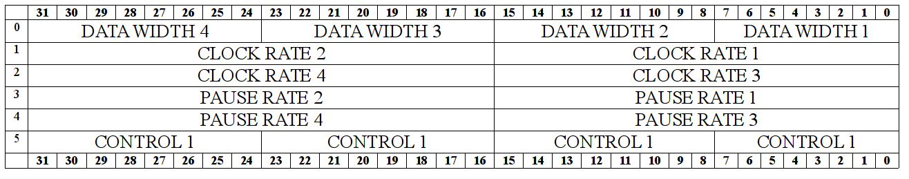
DATA WIDTH - Determines the maximum number of bits in a single SSI transaction. (digit capacity of the receiving register). Valid values are from 1 to 32It's all the same here - we consider the shift for the required area and write the value with the corresponding function iowriteX
CLOCK RATE - A port that determines the division ratio of the system Clk (33 MHz) for the formation of a Block SSI.
Kdel = (CLOCK RATE) * 2 + 2
PAUSE RATE Port defining the amount of pause after the transaction, in periods Clk (30 ns)
CONTROL 1:
b7 - SSI mode (0 - normal mode, 1 - 16-bit abs mode. Sensor, with wait for the start bit (obsolete data output, only needed for compatibility)).
b6 - Reserved
b5 - Ext4 external signal resolution
b4 - Resolution of the external signal Ext3
b3 - Resolution of the external signal Ext2
b2 - Resolution of the external signal Ext1
b1 - Resolution of continuous sensor polling
b0 - Generate a one-time survey
User Interface Interaction with PCI Driver
There are several ways to communicate the higher software with our driver. One of the oldest, easiest, and most popular ways is the character device.
Character device is a virtual device that can be added to the / dev directory, it can be opened, something written, read, make ioctl calls to set any parameters.
A good example of such a device is a serial driver with its / dev / ttySX
Registering the character device is convenient to make a separate function.
int create_char_devs(struct my_driver_priv* drv); A pointer to our private structure is necessary for the subsequent initialization of the file object, so that with each user open / read / write / ioctl / close call we will have access to our private structure and will be able to perform read / write operations to the PCI device.
It is convenient to call create_char_devs () in the my_driver_probe () function, after all initializations and checks.
In my case, this function is called create_char_devs (), in the plural. The fact is that the driver creates several of the same name (but with different digital indices at the end of the name) character device, one per channel of the LIR941 board, this allows you to conveniently, independently and simultaneously work with several connected sensors at once.Creating a character device is pretty simple.
We determine the number of devices, allocate memory and initialize each device with the configured file_operations structure. This structure contains references to our file operations functions that will be called by the kernel when working with a device file in user space.
Inside the kernel, all / dev devices are identified by a pair of ids.
<major>:<minor> Some major identifiers are reserved and are always assigned to specific devices, other identifiers are dynamic.
The major value is shared by all devices of a specific driver; they differ only in the minor identifiers.
When you initialize your device, you can set the value to major with your hands, well, it’s better not to do this, since you can arrange a conflict. The best option is to use the MAJOR () macro.
Its application will be shown in the code below.
In the case of a minor, the value usually coincides with the sequence number of the device, when created, starting from zero. This allows you to find out which particular device / dev / device-X is accessed from the kernel space - just look at the minor available in the handler for file operations.
Identifiers: displayed by the ls utility with the -l option
for example, if you run:
$ ls -l /dev/i2c-* crw------- 1 root root 89, 0 . 30 21:59 /dev/i2c-0 crw------- 1 root root 89, 1 . 30 21:59 /dev/i2c-1 crw------- 1 root root 89, 2 . 30 21:59 /dev/i2c-2 crw------- 1 root root 89, 3 . 30 21:59 /dev/i2c-3 crw------- 1 root root 89, 4 . 30 21:59 /dev/i2c-4 The number 89 is the major identifier of the driver for the i2c bus controller, it is common to all channels of i2c, and 0.1,2,3,4 is the minor identifier.
An example of creating a set of devices.
#include <linux/cdev.h> #include <linux/device.h> #include <linux/kernel.h> #include <linux/slab.h> #include <linux/uaccess.h> #include <linux/fs.h> // 4 #define MAX_DEV 4 // static int mydev_open(struct inode *inode, struct file *file); static int mydev_release(struct inode *inode, struct file *file); static long mydev_ioctl(struct file *file, unsigned int cmd, unsigned long arg); static ssize_t mydev_read(struct file *file, char __user *buf, size_t count, loff_t *offset); static ssize_t mydev_write(struct file *file, const char __user *buf, size_t count, loff_t *offset); // file_operations static const struct file_operations mydev_fops = { .owner = THIS_MODULE, .open = mydev_open, .release = mydev_release, .unlocked_ioctl = mydev_ioctl, .read = mydev_read, .write = mydev_write }; // , struct my_device_data { struct device* mydev; struct cdev cdev; }; // // // , static int dev_major = 0; // , /sys // udev static struct class *mydevclass = NULL; // my_device_data, // , static struct lir_device_data mydev_data[MAX_DEV]; int create_char_devs() { int err, i; dev_t dev; // err = alloc_chrdev_region(&dev, 0, MAX_DEV, "mydev"); // major dev_major = MAJOR(dev); // sysfs mydev mydevclass = class_create(THIS_MODULE, "mydev"); // for (i = 0; i < MAX_DEV; i++) { // file_operations cdev_init(&mydev_data[i].cdev, &mydev_fops); // - mydev_data[i].cdev.owner = THIS_MODULE; // cdev_add(&mydev_data[i].cdev, MKDEV(dev_major, i), 1); // /dev/mydev-<i> // <i> mydev_data[i].mydev = device_create(mydevclass, NULL, MKDEV(dev_major, i), NULL, "mydev-%d", i); } return 0; } The mydev_open () function will be called if someone tries to open our device in user space.
It is very convenient in this function to initialize the private structure for an open device file. In it, you can save the minor value for the current open device.
You can also put a pointer to some more global structures to help interact with the rest of the driver, for example, we can save a pointer to my_driver_priv, which we worked with earlier, in this place. A pointer to this structure can be used in ioctl / read / write operations to execute hardware queries.
We can define this structure:
struct my_device_private { uint8_t chnum; struct my_driver_priv * drv; }; Opening function
static int mydev_open(struct inode *inode, struct file *file) { struct my_device_private* dev_priv; // minor unsigned int minor = iminor(inode); // dev_priv = kzalloc(sizeof(struct lir_device_private), GFP_KERNEL); // drv_access — my_device_private, // , PCI dev_priv->drv = drv_access; dev_priv ->chnum = minor; // // , file->private_data = dev_priv; // 0, open() return 0; } Read and write operations are fairly simple, the only “nuance” is the lack of security (or even impossibility) of direct access of the user application to the kernel memory and vice versa.
In this regard, to obtain data written using the write () function, you must use the kernel function copy_from_user () .
And when executing read (), you must use copy_to_user () .
Both features come with various checks and ensure safe data copying between the core and user space.
static ssize_t mydev_read(struct file *file, char __user *buf, size_t count, loff_t *offset) { // , open() struct my_device_private* drv = file->private_data; uint32_t result; // - // get_data_from_hardware, result = get_data_from_hardware(drv->drv, drv->chnum); // if (copy_to_user(buf, &data, count)) { return -EFAULT; } // return count; } static ssize_t mydev_write(struct file *file, const char __user *buf, size_t count, loff_t *offset) { ssize_t count = 42; char data[count]; if (copy_from_user(data, buf, count) != 0) { return -EFAULT; } // data, 42 - // // return count; } The ioctl () call handler takes as its arguments the actual ioctl number of the operation and some transmitted data as arguments (if necessary).
The ioctl () operation numbers are determined by the driver developer. It's just some kind of "magic" numbers behind the readable define.
These numbers should be known to the user program, so it is convenient to take them somewhere as a separate header file.
Ioctl handler example
static long mydev_ioctl(struct file *file, unsigned int cmd, unsigned long arg) { struct my_device_private* drv = file->private_data; switch (cmd) { case MY_IOCTL_OP_1: do_hardware_op_1(drv->drv, drv->chnum); break; case MY_IOCTL_OP_2: do_hardware_op_2(drv->drv, drv->chnum); break; .... default: return -EINVAL; }; return 0; } The mydev_release () function is called when the device file is closed .
In our case, it is enough just to free the memory of our private file structure.
static int mydev_release(struct inode *inode, struct file *file) { struct my_device_private* priv = file->private_data; kfree(priv); priv = NULL; return 0; } In the function to destroy a character device, you must delete all created devices, destroy the sysfs class, and free up memory.
int destroy_char_devs(void) { int i; for (i = 0; i < MAX_DEV; i++) { device_destroy(mydevclass, MKDEV(dev_major, i)); } class_unregister(mydevclass); class_destroy(mydevclass); unregister_chrdev_region(MKDEV(dev_major, 0), MINORMASK); return 0; } This function should be called in the __exit method of the kernel module, so that a character device would be destroyed when it was unloaded.
All other work is reduced to the interaction between the character device and the actual equipment, as well as the writing of various auxiliary code.
The full source code for the driver for the LIR941 card can be viewed on Github .
And here is a simple test utility that works with this driver.
Driver testing on real hardware :)
What to read:
wiki.osdev.org/PCI
www.tldp.org/LDP/tlk/dd/pci.html
lwn.net/Kernel/LDD3
Thanks for attention!
I hope this material will be useful to those who decide to write their own driver for something.
Source: https://habr.com/ru/post/348042/
All Articles