FPGA for programmer, state machines (verilog)
The style of describing the finite state machine as a way of thinking
When it is necessary to overcome the innate parallelism of FPGA, and there is a desire to make the scheme work consistently, according to the algorithm, finite automata come to the rescue, about which quite a few academic and practical works are written.
For example, the work is very popular: Clifford E. Cummings, The Fundamentals of Efficient Synthesizable Finite State Machine Design using NC-Verilog and BuildGates . Whenever experts decide to discuss how to write finite automata correctly , someone must get this publication.
The article has become so authoritative that many do not even try to analyze the arguments of the author. In particular, there is an opinion that professionals always use the two-part method of describing finite automata, meaning the description of finite automata in 2 always blocks. This statement continues to cause heated debate, and I want to clarify the differences in the descriptions of the finite state machine with different number of always blocks.
')
In conversations with colleagues, I realized that the debate about how to write finite automata in 1 or 2, 3 always blocks is connected with a different presentation (awareness) of the algorithm being implemented, a different type of thinking. I will try to show it by example.
I believe that this article is not the first article on FSM and Verilog in your life, so I will not explain what a finite state machine is, or how it is described on Verilog, but go straight to the point.
Imagine you are at home, you need to go to the store, buy bread, and come back. Implementing this behavior is simple - it is an algorithmic sequence of actions, it can be described as follows:
- Get dressed and go out
- Go to the store, take the bread
- Pay it on hand
- Go home and get undressed
For many, such a description will seem natural. A clear sequence of actions, similar to the lines of the program. However, the same algorithm can be described in another way:
- From the house go to the street
- From the street go to the store (bread department)
- From bread dressed to go to the cashier
- From the ticket office heading home
wherein
- when we are at home we are naked
- when we are on the street we are dressed
- when we are in the store (bread department) - we take bread
- when we are at the cash desk - we pay money
Interestingly, at least someone now thought that the latter option is more logical than the first one?
One way or another, both of these descriptions have a representation of a finite state machine. The first is in the form of a description with one always block, and the second with two or three. I will make a reservation that the description in 2 and 3 of the always block is the twin brothers, differing only in technical nuances that are not important to us now.
Let us show how descriptions are presented as an automaton:
We have automaton states: HOME_STATE, STREET_STATE, MARKET_STATE, CASHIER_STATE, there are automaton outputs (our actions): GET_DRESSED_ACT, UNDRESS_ACT, TAKE_BREAD_ACT, PAY_MONEY_ACT
Description with 1 always block, looks like this:
always @(posedge clk) begin if(reset) begin State <= HOME_STATE; Action <= UNDRESS_ACT; end //--------------------------------- else begin case(State) //----------------------------- HOME_STATE: begin Action <= GET_DRESSED_ACT; // State <= STREET_STATE; // end //----------------------------- STREET_STATE: begin State <= MARKET_STATE; // Action <= TAKE_BREAD_ACT; // end //----------------------------- MARKET_STATE: begin State <= CASHIER_STATE; // Action <= PAY_MONEY_ACT; // end //----------------------------- CASHIER_STATE: begin State <= HOME_STATE; // Action <= UNDRESS_ACT; // end //----------------------------- default: // ( , ) begin State <= HOME_STATE; // Action <= UNDRESS_ACT; // end endcase end end Now the description with 2 always blocks:
// always @(posedge clk) begin if(reset) State <= HOME_STATE; else State <= NextState; end // : always @(*) begin case(Sate) //----------------------------- HOME_STATE: // begin Action = UNDRESS_ACT; // NextState = STREET_STATE; // end //----------------------------- STREET_STATE: // begin Action = GET_DRESSED_ACT; // NextState = MARKET_STATE; // end //----------------------------- MARKET_STATE: // begin Action = TAKE_BREAD_ACT; // NextState = CASHIER_STATE; // end //----------------------------- CASHIER_STATE: // begin Action = PAY_MONEY_ACT; // NextState = HOME_STATE; // end //----------------------------- default:// ( , ) begin NextState = HOME_STATE; // Action = GET_DRESSED_ACT; // ( ) end endcase end I want to draw attention to the features of these 2 descriptions, which are the cause of the holy war for the number of blocks always .
1 always block
HOME_STATE: begin Action <= GET_DRESSED_ACT; // State <= STREET_STATE; // end 2 always blocks
HOME_STATE: // begin Action = UNDRESS_ACT; // NextState = STREET_STATE; // end An automaton with 1 always block in the current state determines what actions it is going to do next, without worrying about what it is doing now. And an automaton with 2 always blocks, in the current state, determines what it is doing now, and does not care about what it will do next or have done before.
It is impossible to unequivocally say which behavior is better or more correct. Everything strongly depends on the task, on the algorithm implemented by the automaton. To demonstrate, change the situation. Now you have a home , a job , a bar . You go to work - to work , to the bar - to drink beer . You go to the bar both from home on weekends and from work on Friday.
In the first implementation, with 1 always , you need to carefully monitor where you are going to go in order not to accidentally start drinking beer at work or working in a bar . In the second implementation, with 2 always blocks, you are protected from this. Everything is clearly defined: the state at work - we work , the state in the bar - we drink beer .
On the other hand, in the description with 2 always blocks, coming to the bar from work, you can not not drink beer. The state in this implementation rigidly fixes the action of the bar - we drink beer . And in the description with 1 always block, your actions in the bar are determined at the moment of exit from the past state. From work, you can go to the bar and drink whiskey . Every second trip from home to the bar can end with a party . The current status in the bar does not limit you.
Both machines have their place in projects, just need to correctly determine which features will be useful in a particular situation.
If you have a complex network of transitions and you get into different states in many ways, it makes sense to use a scheme with 2 always blocks. You will not have a chance to forget to set one of the exits of the machine at the next transition.
On the other hand, if you write a simple automaton with an almost linear structure, you can use the description with 1 always block. In fact, you specify the sequence at the output, and you use the states simply to organize sequential execution. Since the outputs of the machine do not depend on the current state, it will not be necessary to prescribe their value in each state, the description will be shorter and more logical.
In the article with which we started, it is well shown why it is necessary to use descriptions with 2 and 3 always blocks, and a description with 1 always block is marked as the worst. The author recommends avoiding such a description. Therefore, I would like to give an example of a real interface convenient for description in 1 always block and protect this kind of description. For comparison, I will give the same machine described in 3 always blocks. You need 3, not 2 blocks, because we will use the register output signals.
And so, we have a module that implements writing to asynchronous memory. The module accepts a read or write strobe as input, data and write address, read address. The output module generates a signal to read or write and read the data. The module manages simple asynchronous memory with the following time diagrams of operation.

The main meaning of the module is to read or write a gate through the gate, “set up a temporary harbor”, withstand specified intervals, and upon completion give 1 clock readiness signal. We need to follow the following intervals
- Rs - the time to set the address and memory selection signal before reading
- Rp - the exposure time of the memory output enable signal until the correct data appears
- Rh - time delay of the memory selection signal after removing the output resolution
- Ws - the time of setting the address, data and memory selection signal before recording
- Wp - the duration of the recording resolution signal
- Wh is the dwell time of the data and address after removing the write enable signal
We will measure the intervals in the number of input frequency cycles and set the intervals with the constants READ_SETUP, READ_PULSE, READ_HOLD and WRITE_SETUP, WRITE_PULSE, WRITE_HOLD.
Description with 1 always block:
module mem_ctrl_1 ( //system side input clk, input reset, input w_strb, input r_strb, input [7:0] s_waddress, input [7:0] s_raddress, input [7:0] s_data_to, output reg [7:0] s_data_from, output reg done, //memory side output reg [7:0] m_address, output reg [7:0] m_data_to, input [7:0] m_data_from, output reg cs_n, output reg oe_n, output reg we ); //------------------------------------------------------ parameter PAUSE_CNT_SIZE = 16; parameter READ_SETUP = 5; parameter READ_PULSE = 3; parameter READ_HOLD = 1; parameter WRITE_SETUP = 5; parameter WRITE_PULSE = 3; parameter WRITE_HOLD = 1; //------------------------------------------------------ reg [PAUSE_CNT_SIZE - 1 : 0] PCounter; //------------------------------------------------------ reg [3:0] State; localparam [3:0] IDLE = 0; localparam [3:0] PREPARE_READ = 1; localparam [3:0] READ = 2; localparam [3:0] END_READ = 3; localparam [3:0] PREPARE_WRITE = 4; localparam [3:0] WRITE = 5; localparam [3:0] END_WRITE = 6; //------------------------------------------------------ always @(posedge clk) begin if(reset) begin done <= 1'b0; m_address <= 8'd0; m_data_to <= 8'd0; s_data_from <= 8'd0; cs_n <= 1'b1; oe_n <= 1'b1; we <= 1'b0; State <= IDLE; PCounter <= 0; end else begin // 0 if(PCounter != 0) PCounter <= PCounter - 1'b1; // , // 1 done <= 1'b0; case(State) //-------------------------- IDLE: begin if(w_strb == 1'b1) // begin cs_n <= 1'b0; m_data_to <= s_data_to; State <= PREPARE_WRITE; m_address <= s_waddress; PCounter <= WRITE_SETUP; end else if(r_strb == 1'b1) // begin cs_n <= 1'b0; m_address <= s_raddress; State <= PREPARE_READ; PCounter <= READ_SETUP; end end //-------------------------- PREPARE_READ: begin if(PCounter == 0) begin State <= READ; oe_n <= 1'b0; PCounter <= READ_PULSE; end end //-------------------------- READ: begin if(PCounter == 0) begin State <= END_READ; oe_n <= 1'b1; PCounter <= READ_HOLD; s_data_from <= m_data_from; end end //-------------------------- END_READ: begin if(PCounter == 0) begin State <= IDLE; cs_n <= 1'b1; done <= 1'b1; end end //-------------------------- PREPARE_WRITE: begin if(PCounter == 0) begin State <= WRITE; we <= 1'b1; PCounter <= WRITE_PULSE; end end //-------------------------- WRITE: begin if(PCounter == 0) begin State <= END_WRITE; we <= 1'b0; PCounter <= WRITE_HOLD; end end //-------------------------- END_WRITE: begin if(PCounter == 0) begin State <= IDLE; cs_n <= 1'b1; done <= 1'b1; end end //-------------------------- default: // begin done <= 1'b0; m_address <= 8'd0; m_data_to <= 8'd0; s_data_from <= 8'd0; cs_n <= 1'b1; oe_n <= 1'b1; we <= 1'b0; State <= IDLE; end endcase end end endmodule Description with 3 always blocks:
module mem_ctrl_3 ( //system side input clk, input reset, input w_strb, input r_strb, input [7:0] s_waddress, input [7:0] s_raddress, input [7:0] s_data_to, output reg [7:0] s_data_from, output reg done, //memory side output reg [7:0] m_address, output reg [7:0] m_data_to, input [7:0] m_data_from, output reg cs_n, output reg oe_n, output reg we ); //------------------------------------------------------ parameter PAUSE_CNT_SIZE = 16; parameter READ_SETUP = 5; parameter READ_PULSE = 3; parameter READ_HOLD = 1; parameter WRITE_SETUP = 5; parameter WRITE_PULSE = 3; parameter WRITE_HOLD = 1; //------------------------------------------------------ reg [PAUSE_CNT_SIZE - 1 : 0] PCounter; //------------------------------------------------------ reg [3:0] State; reg [3:0] NextState; localparam [3:0] IDLE = 0; localparam [3:0] PREPARE_READ = 1; localparam [3:0] READ = 2; localparam [3:0] END_READ = 3; localparam [3:0] PREPARE_WRITE = 4; localparam [3:0] WRITE = 5; localparam [3:0] END_WRITE = 6; //------------------------------------------------------ // always @(posedge clk) begin if(reset) State <= IDLE; else State <= NextState; end //------------------------------------------------------ // always @(*) begin // NextState = State; case(State) //-------------------------------------- IDLE: begin if(w_strb == 1'b1) // begin NextState = PREPARE_WRITE; end else if(r_strb == 1'b1) // begin NextState = PREPARE_READ; end end //-------------------------------------- PREPARE_READ: begin if(PCounter == 0) begin NextState = READ; end end //-------------------------------------- READ: begin if(PCounter == 0) begin NextState = END_READ; end end //-------------------------------------- END_READ: begin if(PCounter == 0) begin NextState = IDLE; end end //-------------------------------------- PREPARE_WRITE: begin if(PCounter == 0) begin NextState = WRITE; end end //-------------------------------------- WRITE: begin if(PCounter == 0) begin NextState = END_WRITE; end end //-------------------------------------- END_WRITE: begin if(PCounter == 0) begin NextState = IDLE; end end //-------------------------------------- default: NextState = IDLE; endcase end //------------------------------------------- // always @(posedge clk) begin if(reset) begin cs_n <= 1'b1; oe_n <= 1'b1; we <= 1'b0; end else begin // //, , NextState case(NextState) //-------------------------------------- IDLE: begin cs_n <= 1'b1; oe_n <= 1'b1; we <= 1'b0; end //-------------------------------------- PREPARE_READ: begin cs_n <= 1'b0; oe_n <= 1'b1; we <= 1'b0; end //-------------------------------------- READ: begin cs_n <= 1'b0; oe_n <= 1'b0; we <= 1'b0; end //-------------------------------------- END_READ: begin cs_n <= 1'b0; oe_n <= 1'b1; we <= 1'b0; end //-------------------------------------- PREPARE_WRITE: begin cs_n <= 1'b0; oe_n <= 1'b1; we <= 1'b0; end //-------------------------------------- WRITE: begin cs_n <= 1'b0; oe_n <= 1'b1; we <= 1'b1; end //-------------------------------------- END_WRITE: begin cs_n <= 1'b0; oe_n <= 1'b1; we <= 1'b0; end endcase end end //------------------------------------------- // // always @(posedge clk) begin if(reset) begin m_address <= 8'd0; m_data_to <= 8'd0; s_data_from <= 8'd0; done <= 1'b0; end else begin if ((State == IDLE) && (NextState == PREPARE_WRITE)) begin m_address <= s_waddress; m_data_to <= s_data_to; end else if ((State == IDLE) && (NextState == PREPARE_READ)) m_address <= s_raddress; //---------------------------------------------------------------- if ((State == READ) && (NextState == END_READ)) s_data_from <= m_data_from; //---------------------------------------------------------------- if ((State == END_READ) && (NextState == IDLE)) done <= 1'b1; else if ((State == END_WRITE) && (NextState == IDLE)) done <= 1'b1; else done <= 1'b0; end end //------------------------------------------- // always @(posedge clk) begin if(reset) begin PCounter <= 0; end else begin // 0, // , // if ((State == IDLE) && (NextState == PREPARE_WRITE)) PCounter <= WRITE_SETUP; else if((State == PREPARE_WRITE) && (NextState == WRITE)) PCounter <= WRITE_PULSE; else if((State == WRITE) && (NextState == END_WRITE)) PCounter <= WRITE_HOLD; //---------------------------------------------------------- else if((State == IDLE) && (NextState == PREPARE_READ)) PCounter <= READ_SETUP; else if((State == PREPARE_READ) && (NextState == READ)) PCounter <= READ_PULSE; else if((State == READ) && (NextState == END_READ)) PCounter <= READ_HOLD; //---------------------------------------------------------- else if(PCounter != 0) PCounter <= PCounter - 1'b1; end end endmodule Here is the result of the modeling work descriptions
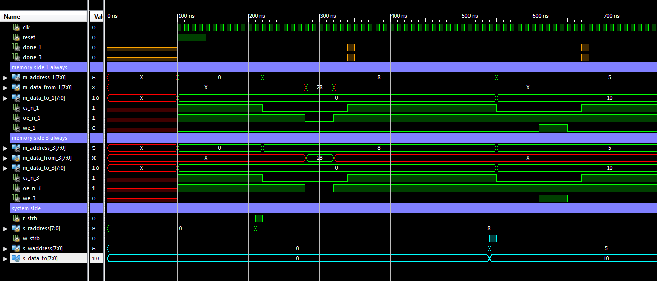
As we see, they behave in the same way and correspond to the desired temporary memory diagrams. The description in the 3 always block turned out to be in a greater number of blocks, otherwise the block of setting the outputs would be much more complicated. Charge the counter, save the data for writing to memory and back we need in one particular clock cycle. To do this, you must either add single-ended states to the automaton, or create structures highlighting these ticks. I preferred the second option and put the structures into separate blocks in order not to complicate the block of assigning the outputs.
Anyway, in this example we see how much more the description is obtained in 3 always blocks (gross 287 lines against 181). It has more places to make a mistake. It is also more difficult to debug. If you looked through these two descriptions, you might have noticed that in the first description the whole picture of the work is immediately visible, and in the second we always see some part. The complete picture is spread throughout the file.
To disassemble the so described foreign machine is a separate “pleasure”. Especially if the conditions of the transitions depend on the outputs of the automaton (in our case, the state sets the counter, and the counter sets the transition condition). First you look at the value of the outputs in the current state, then you fly to the block of transitions and see where we are going in this state and with this value of the outputs. Then again you shake in the block of the task of exits, you watch their changes from a new state.
The automaton described in the 2 always block is a little easier to analyze, its outputs and transitions often lie side by side in the same block, but just until we want to latch the state of the output into the register. Here the registers with the pairwise combinatorial values of their next state begin to appear, then the snap-in conditions begin to be added, and we return to the original exercise.
I hope now the description with 1 always block, lose the title "the worst description, try to avoid it." Of course, you should not always use only this kind of description. When branching networks of transitions 1 block description is really inconvenient. It quickly grows in code volume and ceases to be controlled. However, throwing it out of the development arsenal is definitely not worth it.
Source: https://habr.com/ru/post/347928/
All Articles