Mobile devices from the inside. What is GPT?
What is GPT?
TABLE OF CONTENTS
1. Introduction
We continue to consider the structure of the software ( software ) of mobile devices ( MU ). Today let's talk about the device GPT -memory section. Write about this led me to the publication We study the structure of the MBR and GPT , instead of writing comments to it. I would not like to scold or correct the author, but to supplement the above publication with a bias in the MU .

So, GPT (GUID Partition Table) is:
- first of all, the name of the memory markup scheme ( GPT-scheme ) MU;
- then the name of the section of memory ( GPT-section ) where this scheme is physically located;
- well, also the name of the image file of the GPT memory partition ( GPT file ).
There are two memory markup schemes: MBR and GPT . Each scheme is contained in a separate memory section, called, respectively, MBR or GPT .
')
How the MBR layout is arranged can be found in [1] , and GPT is a different format for describing memory markup - GUID (GUID Partition Table). It is part of EFI (Extensible Firmware Interface), a UEFI standard that is used instead of BIOS to load memory partitions.
Switching to another format eliminated the most significant disadvantage of the MBR format - a small number of sections. If only 4 entries were placed in the MBR with restrictions on the length of the partition and its offset due to the fact that these parameters were described by 32-bit numbers, then 128 entries about the partitions can be placed in the GPT . Moreover, their parameters are already described in the 64-bit number system ...
For compatibility with the old boot standard (BIOS) and for the purpose of protecting the partition description table itself, the GPT partition also starts with the MBR , which describes just one partition — the entire MU memory. The MBR itself is now called "protective" (protective), i.e. PMBR. It is also located in the first memory sector at 0x0000-0x01FF (512 bytes). The Offset field indicates the beginning of the GPT header, and the partition size is set equal to the length of the entire device memory. The partition type is 0xEE (GPT partition).
The essence of the protection of the GPT- section and the whole memory of the MU is as follows. If such a partition opens the tool for working with the MBR markup scheme, it will see an empty unallocated memory consisting only of the markup description section. Accordingly, he will not be able to do anything with this memory.
This is what PMBR looks like , for example, from MU ...:
PMBR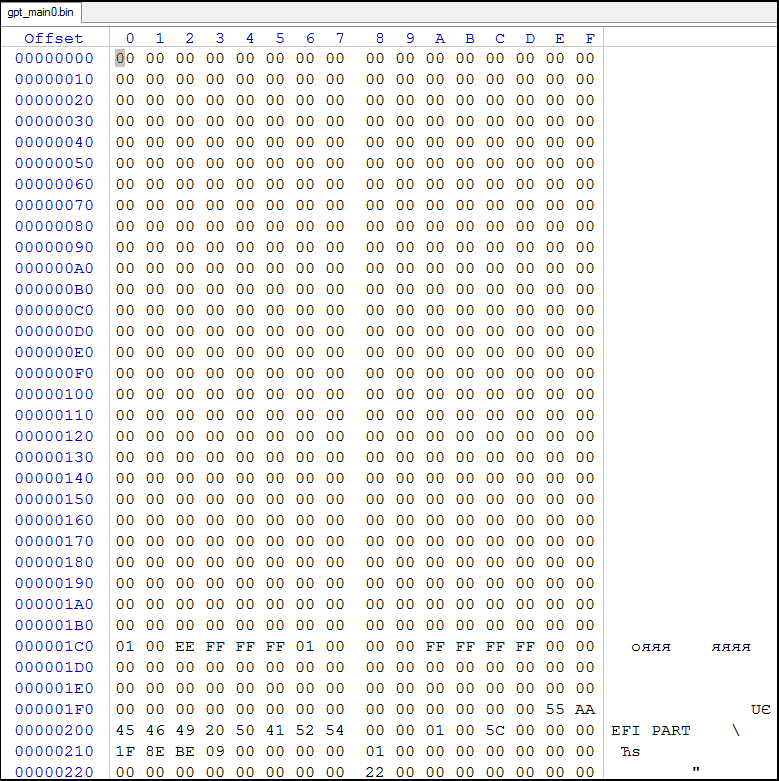
Fig.1 "Protective" MBR, i.e. PMBR
At the address 0x01FE , the signature MBR (0xAA55) is visible.
Let us proceed directly to the structure of the GPT- section.
2. GPT structure
A GPT partition consists of a PMBR , a header, and a table of memory section descriptions.
Immediately after PMBR , i.e. from the address 0x0200 , the GPT header is located, having a length of 0x5C (92) bytes, but occupying the entire sector (512 bytes). Here is how it looks in the same MU :
GPT header
Fig.2 GPT header
It has the following structure:
=============================================================================== | | | | | | | | | | |==========|=================|=======|==========================================| | 0x00 | Magic | 8 | | | 0x08 | Revision | 4 | GPT- | | 0x0C | HeaderSize | 4 | | | 0x10 | HeaderCRC32 | 4 | CRC32 | | 0x14 | Reserved1 | 4 | ; 0 | | 0x18 | MyLBA | 8 | LBA GPT- | | 0x20 | AlternateLBA | 8 | LBA GPT- | | 0x28 | FirstUsableLBA | 8 | LBA | | 0x30 | LastUsableLBA | 8 | LBA | | 0x38 | DiskGUID | 16 | GUID () | | 0x48 | PartitionsLBA | 8 | LBA GPT | | 0x50 | NumberParts | 4 | | | 0x54 | PartitionSize | 4 | | | 0x58 | PartitionsCRC32 | 4 | CRC32 | | 0x5C | Reserved2 | * | | =============================================================================== The Magic field contains the string of characters “EFI PART” - 45h 46h 49h 20h 50h 41h 52h 54h, which is highlighted in turquoise in figure 2 and uniquely identifies the GPT section.
The Revision field highlighted in green contains the version number of the structure of the GPT partition (0x00010000). For example, for GPT version 1.0 it should be 00h 00h 01h 00h
The HeaderSize field, highlighted in orange, contains the size of the header, expressed in bytes. So far it is 0x0000005Ch, which means 92 bytes.
The HeaderCRC32 field, highlighted in pink, contains the header checksum (0x09BE8E1F), calculated using the CRC32 algorithm. When performing the calculation directly, only 92 bytes are taken into account, and 0 is entered in this field before the calculation.
The next field Reserved1 is not selected, is a backup and contains 0.
The field MyLBA , highlighted in dark blue, contains the offset in the placement blocks of the primary GPT partition (0x00000001).
The AlternateLBA field contains the offset in the block placement of the backup GPT partition. It is not indicated.
The FirstUsableLBA field, highlighted in red, contains the offset in the allocation blocks of the first memory sector allowed for use (0x00000022). It is calculated as follows: LBA of the last sector occupied by the primary GPT partition, + 1.
The LastUsableLBA field contains the placement offset of the last memory sector allowed for use. It is calculated as follows: LBA of the first sector of the backup GPT partition is 1. It is not specified.
The DiskGUID field highlighted in blue contains the firmware GUID.
The PartitionsLBA field highlighted in red contains the GPT start offset. In the primary, it is always 2, and in the backup it is LastUsableLBA.
The NumberParts field, highlighted in bright green, contains the size of the partition description table, i.e. the number of partition entries (0x00000018).
The field of PartitionSize , highlighted in pink, contains the size of one partition record in bytes. According to the UEFI Specification, the record size is fixed at 128 bytes or 0x00000080.
The PartitionsCRC field highlighted in red contains the checksum of the partition description table (0x93D54D33) calculated using the CRC32 algorithm. The calculation takes into account all bytes, starting with PartitionsLBA and up to FirstUsableLBA.
The Reserved2 field contains a backup field. Contains 0 to the end of the sector, i.e. 420 bytes for a sector of 512 bytes in size.
Immediately after the title, starting with the address 0x400 , there is a section description table, containing records for each section of memory, including the markup section itself. Here's what she looks like:

Fig.3 Section Description Table
Each 128-byte entry has the following structure:
==================================================================================== | | , | | | | | | | | |===========|========|=====================|=========================================| | 0 | 0x00 | 16 | PartitionTypeGUID | GUID | | 16 | 0x10 | 16 | UniquePartitionGUID | GUID | | 32 | 0x20 | 8 | StartingLBA | LBA | | 40 | 0x24 | 8 | EndingLBA | LBA | | 48 | 0x30 | 8 | Attributes | | | 56 | 0x38 | 72 | PartitionName | | ==================================================================================== The PartitionTypeGUID field, highlighted in red, contains the partition type GUID that defines the file system used to store data in this section. Each file system gets its GUID, which uniquely identifies it. The UEFI standard strictly defines only the following partition type GUIDs:
============================================================================= | GUID | | |======================================|======================================| | 00000000-0000-0000-0000-000000000000 | | | C12A7328-F81F-11d2-BA4B-00A0C93EC93B | UEFI | | 024DEE41-33E7-11d3-9D69-0008C781F39F | , MBR | ============================================================================= Vendors of vendors need to generate their own partition type GUID to identify them. Some known GUIDs can be viewed in [3] .
When writing to memory or to an image file, the GUID value is written in a different order. For example, the EFI system partition GUID is as follows: C12A7328-F81F-11D2-BA4B-00A0C93EC93B. The byte order in GUID spellings is little-endian, and bytes are written backwards only in the first three blocks. For the above GUID, the entry in the partition table will look like this:
28 73 2A C1 1F F8 D2 11 BA 4B 00 A0 C9 3E C9 3B The UniquePartitionGUID field, highlighted in blue, contains the section GUID. It is a unique section identifier, so it is created every time a section is created.
The StartingLBA field, highlighted in green, contains the offset in blocks to the first sector sector (0x00020000).
The EndingLBA field, highlighted in orange, contains an offset to the last sector sector (0x0003FFFF). The size of the partition (PartitionSize) is determined by the formula
PartitionSize = EndingLBA - StartingLBA + 1 The Attributes field, highlighted in purple, contains section attributes (flags). 8 bytes (64 bits) flags are distributed as follows. Bits 0 through 47 (48 pieces) are reserved for general attributes of partition types, and the remaining 16 bits (48 through 63) describe a specific partition.
Here is a brief description of these bits:
================================================ | | | |======|=========================================| | 0 | | | 1 | EFI | | 2-47 | UEFI | | ---- | | | 60 | Read-only ( ) | | 61 | | | 62 | Hidden () | | 63 | | ================================================ The PartitionName field, highlighted in blue, contains a partition label (“modem”) containing a string of text with a zero terminating number of not more than 36 characters, expressed in UTF-16LE encoding.
All that is GPT, we already know, only this is the standard structure of the GPT- section. It turns out that there is a modification ...
Since I found a GPT -section of a different structure when working with an MU based on an Intel chip, then I called its GPT-partition like Intel .
3. What is an Intel GPT partition?
The firmware of Lenovo's new mobile devices (MU), based on Intel chips, has a Gpt memory layout, but the structure of the Gpt file itself differs from the standard one described in [1]. This applies, for example, devices YOGA BOOK YB1-X90.
Compared to the standard Intel structure , the type is reduced to the maximum:
- Removed from the header Guid, checksums, offsets of all partitions except the first one and all standard values or empty, for example, the size of the partition parameter records, the placement of Primary and Backup tables;
- Attributes have been removed from the section parameter description, and the offsets of the first and last block have been replaced by the section size
Since the structure of a Gpt file of this type differs from the standard structure, then for its firmware it is necessary to use a special flasher from Intel - PhoneFlashTool_5.3.2.0.
GPT- section, as well as the standard, consists of:
- title ;
- partition description tables .

Fig.4. The structure of the Intel-type GPT file
Consider the structure of the title.
3.1. The header structure of the new GPT section.
The header has a size of only 12 ( 0x0C ) bytes (against 512 in the standard version):

Fig.5. Intel-type .pt file header
and contains the following fields:
============================================================= | № | | | | | | / | | | | | |=============================================================| | 1 | 0x00 | Magic | 4 | | | 2 | 0x04 | StartLba | 4 | | | 3 | 0x08 | Number | 4 | | ============================================================= The Magic field, marked in blue, contains the number 0x6A8B0DA1 , which identifies the image of the Intel-type GPT partition .
The StartLba field, marked in red, contains the offset value for the placement of the first section of memory.
The Number field, marked in green, contains the total number of sections of memory, i.e. the number of entries in the section description table. The table itself is located immediately after the title.
3.2. The structure of the record description of the new GPT section
The partition description table contains entries containing the parameters of each memory section. The number of records is equal to the number of sections, and the end of the table is not marked.
Each record has a size of 108 ( 0x6C ) bytes, while according to UEFI it contained 128 bytes. This is what the entry for describing a section of the new format looks like:

Fig.6 Recording the section description
and contains the following fields describing the parameters of the section:
============================================================= | № | | | | | | / | | | | | |=============================================================| | 1 | 0x00 | Size | 4 | | | 2 | 0x04 | Label | 72 | | | 3 | 0x4C | GuidType | 16 | GUID | | 3 | 0x5C | GuidPartition | 16 | GUID | ============================================================= The Size field, highlighted in blue in Figure 6, contains the size of the partition, expressed in MB (1024 * 1024 = 1048576 bytes).
The Label field highlighted in red in Figure 6 contains the label of the section, i.e. section name, expressed in UTF-16 encoding.
The GuidType field highlighted in green in Figure 6 contains the section type GUID.
The GuidPartition field highlighted in Figure 6 in yellow contains the GUID of the section itself.
4. Conclusion
Having studied the structure of the GPT -partitioning of memory markers MU , you can proceed to practical exercises.
In the following publications, I will share the experience of re-marking the memory of a MU performed on a GPT scheme.
5. Sources of information
1. "What is MBR?"
2. UEFI Specification, Version 2.7 Errata A
3. GUID Partition Table.
Source: https://habr.com/ru/post/347738/
All Articles