Designing a fire pumping station
At the end of October, talking to the management, I get a task: “We need a series of articles on the practical application of nanoCAD VK programs and Heating . The task is set, go write. "
In thought, he did not notice how he reached his workplace. There are a lot of projects on which you can write an article, but you want something fresher, something special. This, to show immediately that you should not be afraid of domestic software, that it is not worse, and sometimes better than foreign. I come across a correspondence with our user Vyacheslav Zatserkovny from Delta LLC.
Here it is, the first article! Vyacheslav is one of the most interesting and curious users I have come across. His department designs fire safety systems for commercial, warehouse, industrial purposes, and if you look more broadly, he develops any projects related to fire safety (AUPS, SOUE, OMK, ASPZ, SKS, BCH, AUPT, ERW).
Acquaintance with Vyacheslav began six months ago. From a phone call. Vyacheslav was interested in VK nanoCAD , there were many questions about the program, about its interaction with other decisions through the IFC format. The task before Vyacheslav was simple: to find software that allows you to calculate the fire extinguishing system, get the documentation and transfer the 3D-model of the system to another program. I was interested not only in the projects carried out by Vyacheslav’s department, but also in the opportunity to test our BIM-approach. The essence of the approach is that the designer works with the best solution in his field, and can transfer all results to his colleagues, suppliers and customers using the DOC, DWG and IFC formats. The proposed project was suitable for testing this approach as well as possible.
')
I was rarely sent projects with fire fighting. At first glance, they may seem simple, but in fact there is a lot of work on the calculation and selection of equipment. Because of the large distances, it is often necessary to coordinate with subcontractors the places and heights of pipelines in order to avoid collisions.
It took two months to master the program: the user studied its capabilities in his spare time. A small previously completed project was taken as a basis - now all its stages, from the first steps to exporting a 3D model to another program, were to be completed in nanoCAD VK.
So, the project in nanoCAD VK to be! And from mid-summer work began.
It would be sly to say that everything went smoothly. There were enough problems, but Vyacheslav himself will tell about this better:
“I will try to tell you in as much detail as possible about the work on the project of the internal fire-fighting water supply system: what difficulties I encountered and how I solved them.
The program understood independently, asked for help only in extreme cases. After the transition to design in nanoCAD VK (from foreign CAD-systems), there were no difficulties with orientation in the program. The interface is recognizable and intuitive.
We created the structure of the building, loaded a flat base (unfortunately, we did not have 3D architecture). Started laying the pipeline network and equipment placement. It was then that the first problem arose: the situation with equipment for ERW systems is not simple, it was necessary to create new HSS, search the Internet and download graphics for this equipment. Here, tangible support was provided by the specialists of ZAO Nanosoft (Nikolai Suvorov) and the GC ArcSoft (Arseny Smirnov).
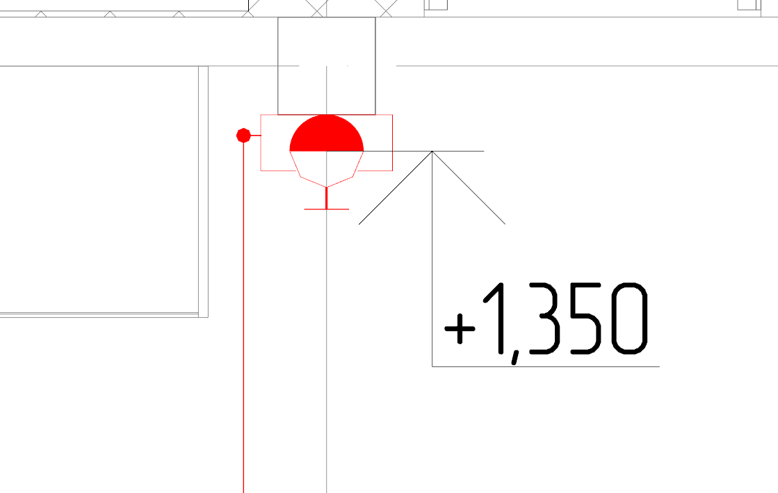
The program allows you to install a pressure gauge, but its installation is assumed directly on the pipe, as a measuring valve. I also needed a pressure gauge on the pipe. I had to create my own HBO.
Display in terms of HGO elements
Next, it took to find and partially work up the schedule, but in the end everything turned out as I wanted.
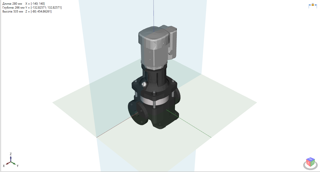
Display equipment in 3D
True, another difficulty was discovered: in the database, the pressure gauge was set to DN 15 and during the checks the program reported that the diameters did not match (the diameter of the pipe on which the pressure gauge was installed was DN 50). In a conversation with the developers, it turned out that the option of installing the nozzle was not taken into account. The remark was accepted, they promised to fix it.
The following problem arose with the flanges of valves and appliances. Since we have flanged valves, it was necessary to install flanges on the pipeline. 90 percent of 3D graphics - without counter flanges, but in 3D it did not look, so we had to add counter flanges. How this can be done, Nikolai Suvorov showed at the webinar "nanoCAD VK: working with 3D graphics . " The proposed method we used. It turned out great, it only remained to add to the database the information that now the fittings and devices are with counter flanges.
Display 3D graphics in the database
Also had to create a new UGO for PC, and with the left and right connection. Well, the graphics - it was already the easiest.
Display in terms of PCBU
The independent creation of the equipment base is connected with the fact that initially the graphics do not have all the necessary properties (dimensions, material, manufacturer, article number on the catalog, accessories and accessories, equipment power, weight). All this information needs to be found and then entered into the database, which significantly increases the design time. Here we must also note that the customer wants to receive the most complete information about the equipment, which means that it will be necessary to work out the possibility of uploading passports to this very equipment when choosing it on the model. The situation could fundamentally change the appearance of equipment databases from manufacturers, but, oddly enough, manufacturers are not yet completely motivated to create such databases ...
After creating a model of the ERW system, the time has come for calculations. Checking the project for errors, we found that as an error (unconnected equipment) additional equipment that is not participating in the system is displayed. The required head exceeds the value of the guaranteed head, and the effect of using pressure boosting pumps is not taken into account in the calculation. The hydraulic calculation itself loses its significance for the project, since it does not help to choose the right pumps for the fire fighting pumping station. We solved the problem using old Excel spreadsheets, which we thought of earlier. We hope that in the next version the developers will correct this annoying flaw and nanoCAD VK will not only be able to help in the selection of the diameter of the pipes, but will also take into account the pumping equipment.
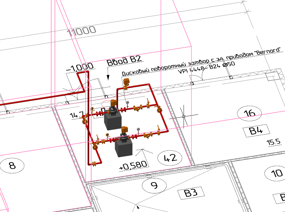
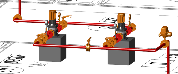
3D-model of the fire pumping station
Now for the design of the project. Modern CAD-systems usually assume that the construction (drawing) of the object model takes place on the Model tab, and everything related to the design of the drawing (frames, stamps, dimensions) is carried out on the Sheet tabs. nanoCAD VK provides a convenient function that allows you to insert into the project a frame with stamps according to GOST. The function significantly speeds up the creation and filling of drawing design elements. But there was no costing a fly in the ointment too: this function works only on the Model tab. The solution was to create a frame in the model, and then copy it onto a sheet, but I would like the functionality to work in the sheets, without requiring any additional operations.
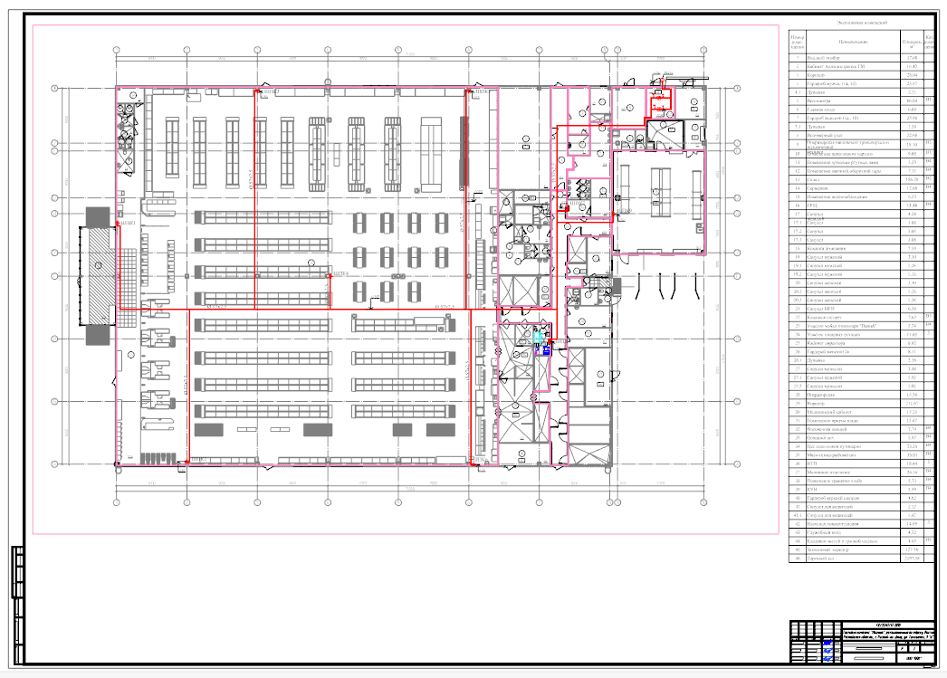
The plan of the internal fire pipeline and fire pumping station
The specification was generated automatically, but the program did not consider additional equipment that is not connected to the network. I hope the developers will eliminate this gap. In addition, setting up a template for a specification is a non-trivial task, to put it mildly. In the program help this setting is not described, so it is difficult for an engineer who is far from programming to understand without the help of specialists.
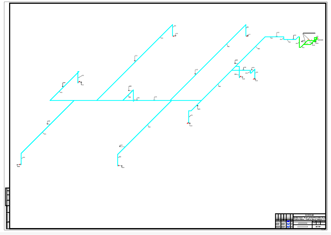
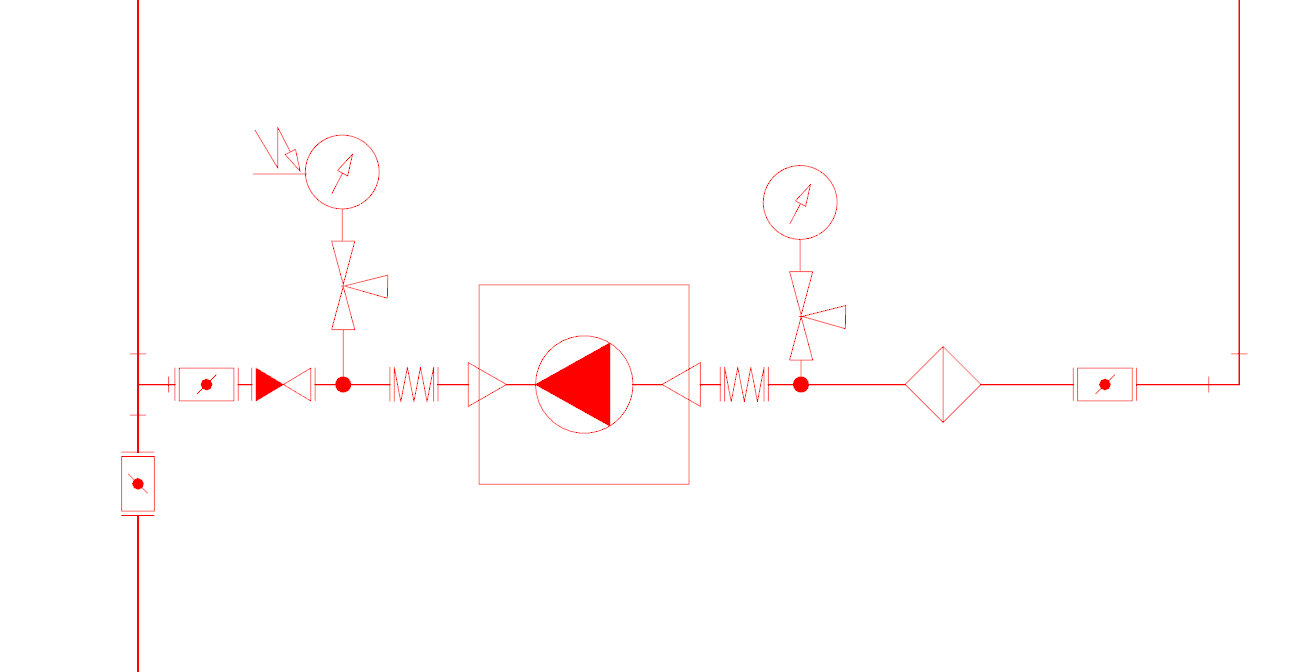
Axonometric scheme of internal fire-fighting water supply and fire pumping station
And finally, on joint design. We uploaded the designed ERW model to the IFC format for its transfer to the customer who works in Revit. The result of our work was a set of drawings in DWG format, designed according to GOST, and an IFC file. When exporting the model to IFC, there were no problems. Now we are waiting for a response from the customer.
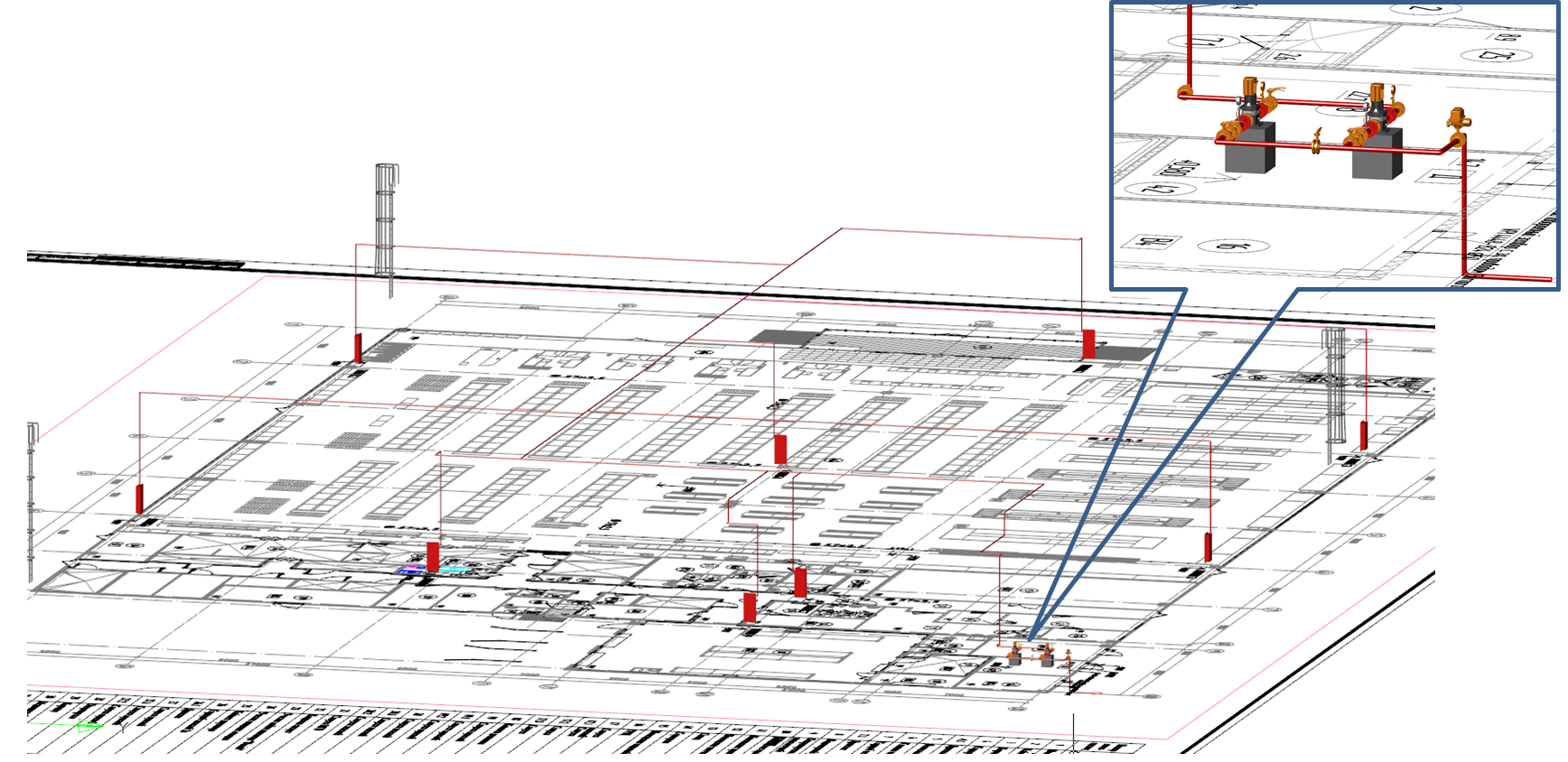
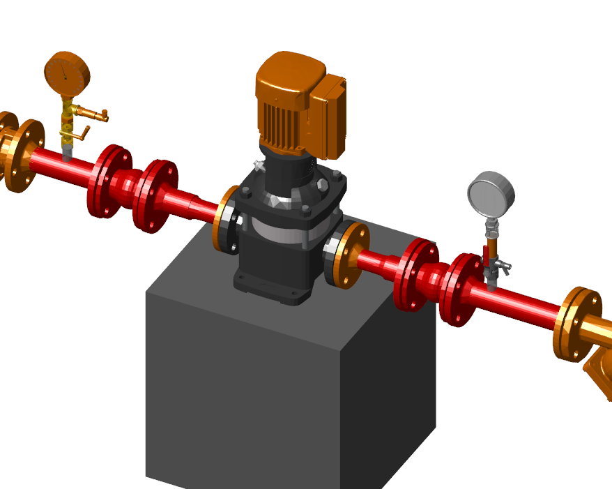
3D-model of the internal fire pipeline and fire pumping station
Summarize. It is possible to design a fire extinguishing pumping station in nanoCAD VK. All necessary documentation was completed on time and in accordance with Russian norms. What pleased the company management.
While working on another project, we used a three-dimensional architectural foundation, uploaded in the IFC format. In nanoCAD VK, the architecture was loaded, but it was established with an offset: it turned out that the architect took the other axes as a base point, as a result of which objects made in nanoCAD VK shifted. The solution may be to set up the export at the customer or to combine the base points of the projects.
We are actively continuing to master the methods of information design and in the future, I hope, we will be able to talk about new successes ... "
Joint work with Vyacheslav on the project was very useful. The developers eliminate the causes of the problems that arose during the creation of the project (pressure gauges, pumps, etc.), so that in the future such difficulties will no longer appear.
In the meantime, the next version was released - nanoCAD VK 8.5. I will say a few words about its innovations.
Implemented the calculation of the joint venture 30.13330.2016, introduced in mid-June 2017. He was very much waited - there were many comments to the joint venture 30.13330.2012. As soon as the new joint venture 30.13330.2016 came into force, they began to ask us when it would appear in the program. And we did not let our users down: nanoCAD VK 8.5 has this calculation.
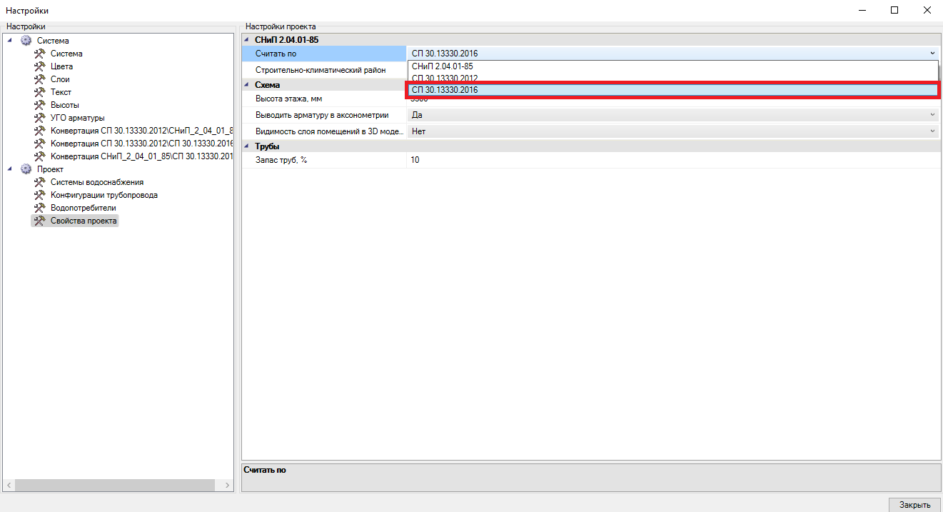
Calculation Settings
Many users asked to add the ability to import premises from the IFC format. We did it. Imported as the geometry of the premises, as well as basic attribute information.
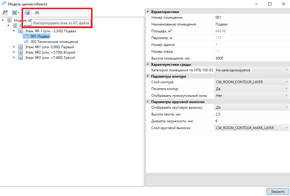
Import floors from an IFC file
Thus, the degree of integration of nanoCAD VK with other BIM-systems has become even higher. This innovation will be appreciated by users, whose allied architects (builders) work in ARCHICAD, Allplan, Revit, etc.
I hope the article turned out informative. The next material is just around the corner - and it will also be devoted to working on an interesting project.
Nikolay Suvorov, SuvorovN
Project Manager nanoCAD VK and Heating
CJSC Nanosoft
The author expresses sincere gratitude to Vyacheslav Yuryevich Zatserkovny, design engineer of Delta LLC, for his help and information provided in preparing this article.
Source: https://habr.com/ru/post/347442/
All Articles