Creating parametric database objects in nanoCAD Mechanics (Part 2)

Work with object code. Script Wizard
In the first part , the process of creating the base object and connecting the geometry to it was described. The created object has a basic script with basic functions, but so far does not contain variables.
The script needs to be improved in accordance with the required functionality of the object. To simplify this task, take the code of a similar base object.
')
As noted in the previous section , the proposed material can be used as a guide for creating and managing parametric objects. It is recommended to use nanoCAD Mechanics version 8.0 and higher. The evaluation version of the program is available here .
The link https://goo.gl/6KhvzH allows you to download the object that will be used as the base for this example.
This object must be connected to the database. To do this, in the Element Base, right-click the Custom folder to open the context menu and select the Import from file command (Fig. 1). Explorer opens, through which we find the desired file and click Open. A new object will be connected.
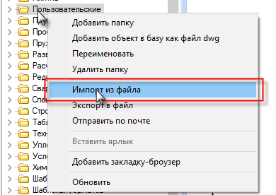
Fig. one
In the Script menu, select Get script from another object , in the Select Part Details window that appears, open the Custom folder, click on the Puck object (Fig. 2).
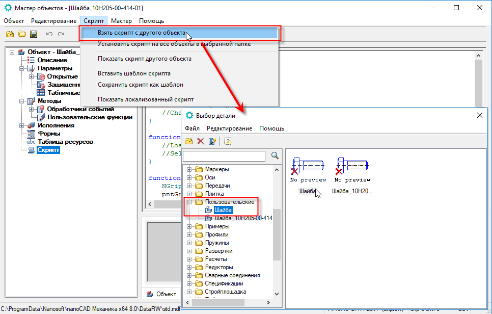
Fig. 2
The script of the new object will be updated (Fig. 3).

Fig. 3
The object from which the script was copied has a simpler geometry. Let's align this script with our object. Add parameters and set new values.
To do this, select the Script Wizard in the Master menu and click Yes in the dialog that appears (fig. 4).

Fig. four
The basic properties window opens. Add and adjust the information as shown in Fig. 5. Click Next .
In the field Specification enter the name of the object in the form in which it will be displayed in the specification.
The value in the Order field adjusts the overlapping of objects relative to each other in the assembly drawing.
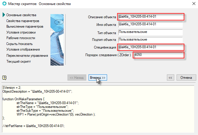
Fig. five
In the Parameters Properties window, add the missing parameters and set values to them. Already available parameters are adjusted.
For our example, we set the following values:
b = 4; B = 6; D = 71.5; D1 = 0.75 * D; d = 30; f = 1; l = 0
Make all the parameters editable: select the parameter, click Available for editing (Fig. 6).
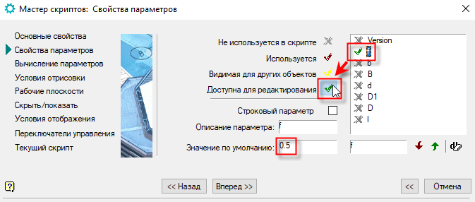
Fig. 6
In order to add a parameter, enter a new designation in the name field of an already existing parameter and click on the Add Parameter button, and then enter the value that will be assigned by default to the created parameter (Fig. 7).
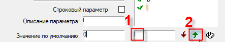
Fig. 7
In the next step, we check the sequence of parameters. For proper execution of the script, the parameter D must be higher than D1 , since the latter is given by the formula through the first. If necessary, change the position of the buttons Order of parameters (Fig. 8).

Fig. eight
At the next step, without changing anything, click Next (fig. 9).
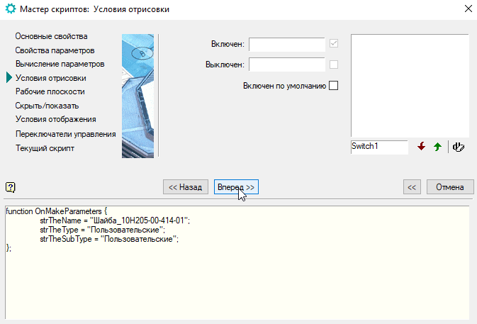
Fig. 9
Now add a description of the work plane - this is needed for the imposition of dependencies between other components. Press the button Add plane , set the orientation OYZ and enable the option Available for editing by others (Fig. 10). Push Forward .
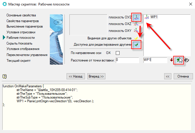
Fig. ten
The next two steps we go through without making changes (Fig. 11).
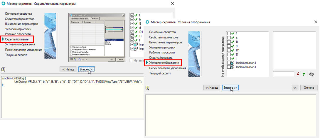
Fig. eleven
In the Control Switches window , we control the variable Draw object at the time of insertion : this option should be enabled (Fig. 12).
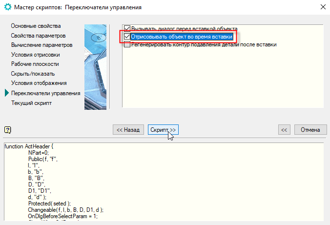
Fig. 12
At the final step of the Script Wizard, you can view the generated program code and, if necessary, return to any of the completed steps to make changes.
Click OK and save the script (Fig. 13).
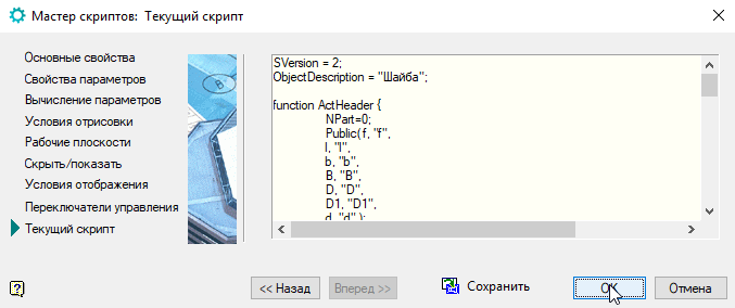
Fig. 13
Now you can check the work of the new object. Save the changes made to the object and close the Object Wizard .
In the Base of elements we find the created object (the Custom folder). If it is not displayed, click the Refresh button on the toolbar.
 . We click on the object and move the mouse pointer to the model space. Select the insertion point and direction. A window with parameters will appear. In the Value field, you can change the value of any parameter. In the left part of the window, the view selection is available Choosing one or another type, you can see its image in the preview window - this is very convenient when the object has many types.
Change the value of B to 4, and b to 2, click OK . The geometry of the washer will change accordingly (Fig. 14).
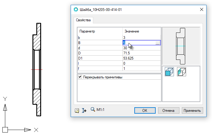
Fig. 14
Double-click on the object, you can return to the edit mode of the puck, and then change the parameters again, but this is convenient only if such changes are made extremely rarely. Given that the washer is one of the products that are constantly used in engineering design, and may have more than a dozen designs, this option is not entirely acceptable. It is more correct to create additional performances with new values, which will save you from unnecessary actions in the future.
This, as well as how to create assembly dependencies and manage them, will be discussed in the next section .
Source: https://habr.com/ru/post/347328/
All Articles