Autopilot simulation on a flight simulator
Is it possible to use a longitudinally located semiconductor gyroscope, which measures the angular speed of the turn of the aircraft, to keep the roll? Let's check it on the flight simulator with an external autopilot. And I would also like to check the aircraft control algorithms. This capability is provided by the XPLANE flight simulator.
Pic1
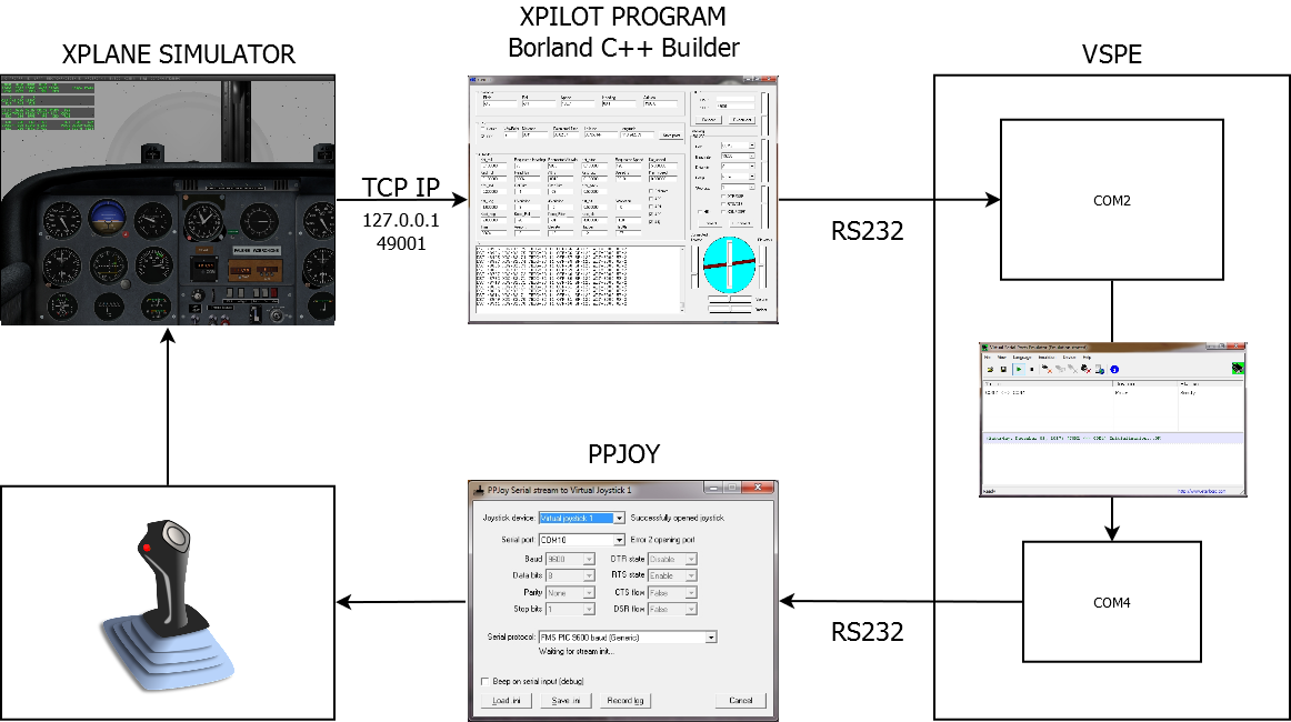
Why XPLANE? It allows you to output data from the sensors of a simulated aircraft into other programs or computers by various means. I chose the UDP protocol for this. In fig. 1 shows a block diagram of a simulation complex. An example of one flight can be seen in the video . The video shows a manual take-off, the withdrawal of an aircraft from a corkscrew during a fall, a flight along the route, turns with loss of height and climb, the landing of the aircraft, manual control of the course and height, and also contains instructions for setting up the X-Plane simulator and autopilot program.
PPJOY and VSPE
To control the aircraft in simulators is usually used a joystick. For training in the management of radio-controlled aircraft are also used appropriate simulators. For interfacing standard remote controls with simulators, there is a PPJOY program that converts the input data stream of an RS232 interface created by certain rules into control signals of a virtual joystick. The program also contains the driver, which is defined in the system as a joystick. Program description PPJOY can be found in the public domain on the Internet. Here you can find a program that can work with Win7. Unfortunately, the driver (64b) included in the program does not have a digital signature and therefore has to run the system in test mode. The standard stream for PPJOY is usually formed by a special module on some controller (for example, PIC), which is connected to the output of the “trainer” of the remote control, where the PPM protocol is used. In this project, the autopilot program forms the stream in accordance with the RS232 standard. The development began with the closure of the OS loop through the external physical COM ports of the computer. At the same time it is possible to use different computers for the simulator and autopilot, which is important for very weak computers. Now, due to the massive absence of COM ports on computers and a sufficiently high power of computers, when even the weakest computers are able to work in such a system, the VSPE (Virtual Serial Port Emulator) program is used. The program allows you to create a pair of ports inside the computer, and not use external ports. For normal operation of the program, you will probably first have to create the appropriate COM ports using Windows tools, and then you can use them in the VSPE and PPJOY programs. Hardware converters for radio remote controls appeared with different conversion rules, therefore it is necessary to select the mode with a frequency of 19200 bps in the PPJOY program. This option is implemented in the autopilot program.
UDP
To receive data from the sensors of the X-Plane aircraft, the simulator is configured in the mode of issuing data via a network UDP protocol. To do this, as shown in the movie , configure the simulator to output data from the aircraft’s “sensors” via the network to the selected IP address and the specified port. In this case, the local IP address is 127.0.0.1 and port 49001 and data is output at a rate of 20 times per second. In addition to this setting, you must correctly select the sensors from which you want to transfer data to the autopilot. It is necessary in the simulator to establish the output field 02 (speed, vertical speed), 16 (angular velocity), 17 (pitch, roll, courses) and 18 (latitude, longitude, altitude). You can also customize the display of these parameters on the screen.
Autopilot
The autopilot program is written in the Borland C ++ Builder 6 environment. The "Instruments" field (Fig.11) shows the initial data from the sensors, which are updated 20 times per second. Here we see the Pitch (Pitch, degrees), which is calculated by the accelerometer in the radio-controlled aircraft, Roll (Roll, degrees), which is calculated by the longitudinal gyro measuring the turn speed of the aircraft. It should be noted here that the pitch in the simulator I take here is real, and not from the accelerometer, although in a real airplane I calculate the pitch from the accelerometer, which means that the sharp acceleration during acceleration will “feel” as an additive to the positive pitch. This is clearly seen in the video fragments of the tests: when it accelerates, the plane immediately raises its tail. This is different from reality. But the roll is really calculated by the angular velocity of the turn of the aircraft. The calculated value of the roll and is shown in the form of a conditional artificial horizon in the lower right corner of the program. (Fig.2) The pitch value shows the slider in the center of the artificial horizon. The next window is the air speed, the value of which is usually obtained from the Pitot tube, the next window is the course we receive from the magnetic compass, the next field is the height. Below is a GPS panel.
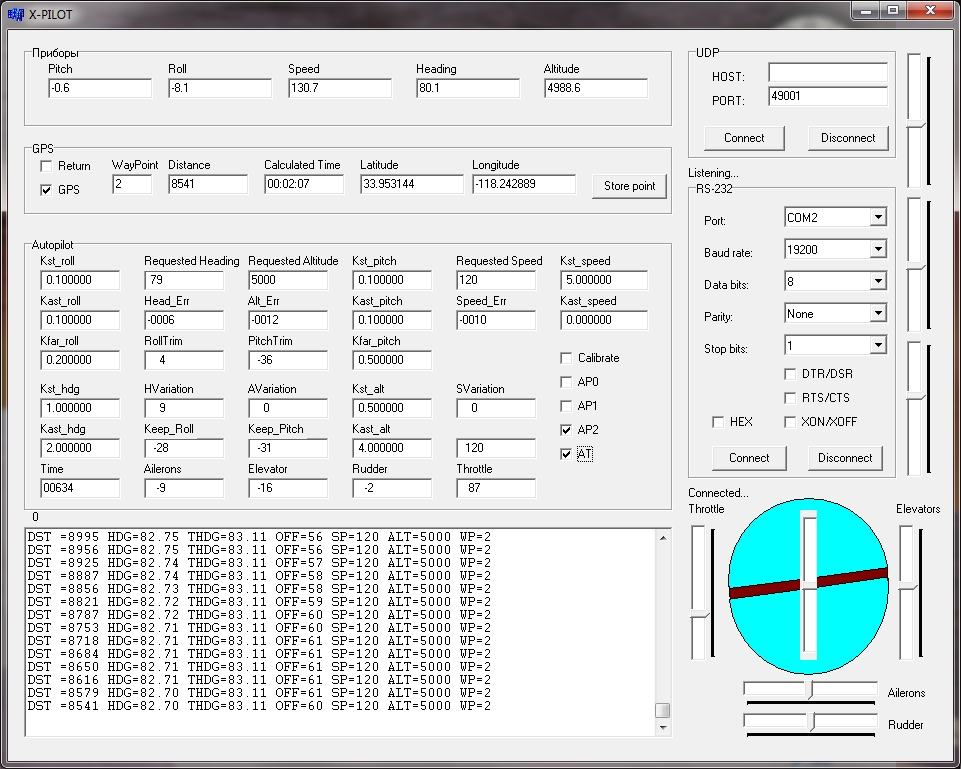
Fig. 2
Checkbox GPS includes flight on the route recorded in the table. At the same time, the fields Requested Heading, Requested Altitude and Requested Speed are automatically filled from the structure
typedef struct WPNT {int pid; int speed; int altitude; int heading; int latitude; int longitude; } WPNT;
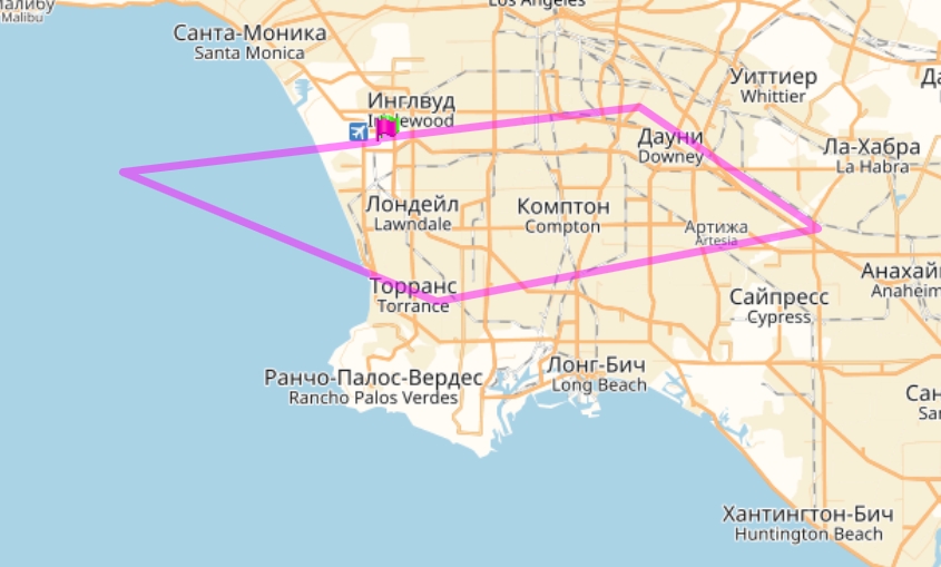
In the demo, the structure contains an example of a route near Los Angeles Airport. (Pic 3)
To change the route, you need to change the structure and recompile the project . If GPS is off, these fields can be filled in manually. Activation of the value in the field occurs when you double-click the mouse. Checkbox Return allows you to return to the point memorized when you press the Store Point button.
Pic.3
WayPoint - the number of the route point; Distance - distance to the next waypoint; Calculated Time is an approximate time to reach the next point (approximately because the wind speed is not taken into account), and then the GPS coordinates are latitude-longitude. Top right, the UDP server panel. Below is the RS232 port control panel. Here you should change only the port number. The remaining parameters are strictly defined by the interaction with the virtual joystick.
Autopilot panel options:
Legend: RW - change allowed, RO - only for look, RWP- change allowed partially
Kst_roll (RW) - static OS loop gain (feedback) for roll
Kast_roll (RW) -astatic OS Loop Gain
Kfar_roll (RW) - roll trimming ratio
Kst_hdg (RW) - static gain for keeping course
Kast_hdg (RW) —Astatic Gain Retention Gain
Time (RO) - flight time, seconds.
Requested Heading (RWP) - requested course, degrees (Manual or from the table if GPS is on)
Head_Err (RO) - Course error, degrees
RollTrim (RO) - roll trimming amendment
HVariation (RO) - rate of change of course Gardus / sec.
Keep_Roll (RO) - roll held, degrees
Ailerons (RO) - aircraft aileron position
Requested Altitude (RWP) - requested altitude, feet (Manual or from a table if GPS is on)
Alt_Err (RO) - Error in height, feet
PitchTrim (RO) - Pitch Trim Amendment
AVariation (RO) - the rate of change of height of feet / sec.
Keep_Pitch (RO) - pitch held (degrees)
Elevator (RO) - aircraft elevator position
Kst pitch (RW) - static gain of the OS loop in pitch
Kast pitch (RW) -astatic OS loop pitch gain
Kfar_ pitch (RW) - pitch trimming coefficient
Kst_alt (RW) - static gain for height retention
Kast_alt (RW) - astatic gain for height retention
Rudder (RO) - aircraft rudder position
Requested Speed (RWP) - requested speed, miles / hour (knots) (Manually or from a table (GPS on))
Speed_Err (RO) - speed error (knots)
SVariation (RO) - rate of change of speed (knots)
Keep_Throttle (RO) - held speed (knots)
Throttle (RO) - RUD Position
Kst_speed (RW) - static gain for speed retention
Kast_speed (RW) —Astatic Gain for Holding Speed
Calibrate - ChechBox Joystick Calibration Enable
AP0 - CheckBox Autopilot Mode 0 - Hold Roll = 0 and Pitch = 0
AP1- CheckBox Mode 1 - Hold the current height and current course
AP2- CheckBox mode 2 - keeping heading and altitude on the table (GPS on) or on set values (GPS off)
AT - CheckBox - traction machine
Around "artificial horizon" there are sliders, with their help, you can manually control the aircraft in case of disconnection of the autopilot or traction machine. There are three more sliders to the right from the edge, these are the components of the elevator control: (output for debugging)
top - the static component of TrackAltErr
medium - astatic component of TrackVarErr
middle - trimming component TrackTrim
The current log is displayed in the field below:
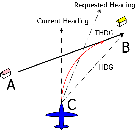
DST - distance to the next point in feet (CB in Fig. 13)
HDG - heading directly to the next waypoint (C-B in Figure 13)
THDG - the course with which you should fly up to the next point (A-B in Figure 13)
OFF - offset from the desired trajectory in feet (the distance from point C to the AB line Fig.13)
SP - required airspeed
ALT - required flight altitude
WP - the next waypoint
GPS
Figure 4 shows the algorithm of the autopilot to maintain the course. Suppose that the task is to fly from point A to point B. Suppose that for some reason the plane was at point “C”. There are various options to reach point B. For example, you can fly directly to her course HDG, but then the approach to the point will be performed with the wrong course. If, for example, there is a landing strip, then landing will definitely not work. Therefore, an algorithm is implemented here, in which, if the plane is very far from a given trajectory, then it flies at the shortest distance perpendicular to THDG (True HDG). As soon as he approaches a certain distance of the turning circle to THDG, the autopilot will begin to change this course (Requested Heading), which will gradually become equal to THDG. Thus, by the time the deviation from the route (OFF) becomes zero, all four courses: Current Heading (the current aircraft course on the Instruments panel), Requested Heading, THDG and HDG on the bottom panel should converge and show the same thing. Such an algorithm now leads to the fact that until the plane reaches a given point, it “does not think” of the next one, and a large unnecessary loop is obtained. The solution may be the transition to the next point at a distance of double radius of the aircraft. At the moment, the conditions for making a decision about reaching a point begin to be checked when the aircraft approaches a given point at a distance shorter than
Pic.4
radius of turn RadRazv. The decision to move to the next point is made either when approaching it less than 50 ft or at the beginning of the distance from this point, if the plane did not fall into a circle with a radius of 50 ft. These are the most interesting moments of the program.
Trimming
As it turned out, the phrase "remove the force from the steering wheel" was not an empty sound. All attempts to make the feedback system in pitch so as to accurately maintain altitude, and at the same time cover the entire range of changes in flight modes, were in vain. Either the plane enters an unstable mode with fluctuations in height with a large gain of the OS loop, or does not accurately maintain the altitude. In addition, at high speed, the lift force can become so large that the elevator cannot cope (due to insufficient gain of the operating system loop), and the plane starts to gain altitude all the time. Or it decreases, not having the opportunity to reach large angles of attack at low speed. Thus, the elevator trimming system is applied with the following algorithm:
- If there is a task to increase the height and the height really grows, then trimming is not performed.
- If there is a task to increase the height, but it falls, or does not change, then the stabilizer will be trimmed into the set until the climb begins.
- If a reduction is required and a reduction occurs, then trimming is not performed.
- If a reduction is required, but at the same time the height does not change or is climbing, then the elevator is trimmed down.
Trimming is much slower than the control of autopilot 0, so the self-excitation of the feedback loop does not occur.
Landing
As you know, the most difficult element of the flight is landing. Since my autopilot is for a radio-controlled model, landing requirements can be simplified. Here, landing is performed in planning mode. In this case, the autopilot is given a task when approaching the landing site (the landing course is held by GPS) to keep the speed 0 and the height, for example, about 200 ft - a bit more than the height of the strip. At the same time, the autopilot keeps the aircraft in the correct flight position, gradually increasing while reducing the angle of attack. Such a landing is not suitable for heavy aircraft, they need not require a zero speed, but the minimum for a given aircraft configuration, while not reaching supercritical angles of attack. In the film, you can see the landing and also see how the autopilot algorithms work when trimming and flying along the route. This is in the simulator. Landing real aircraft can be seen in the test 10/17/2017 . It did not occur normally due to the discharge of the battery, but it is quite beautiful, i.e. as intended.
')
Source: https://habr.com/ru/post/346882/
All Articles