Simulating iridissension: shader CD-ROM
This tutorial is about iridissention . In this tutorial, we explore the very nature of light in order to understand and recreate the behavior of the material that creates color reflections. Tutorial is designed for game developers at Unity, but the techniques described in it can be easily implemented in other languages, including Unreal and WebGL.

The tutorial will consist of the following parts:
Iridiscence is an optical phenomenon in which objects change colors as the lighting angle or angle of view changes. It is because of this effect that the bubbles have such a wide palette of colors.
')
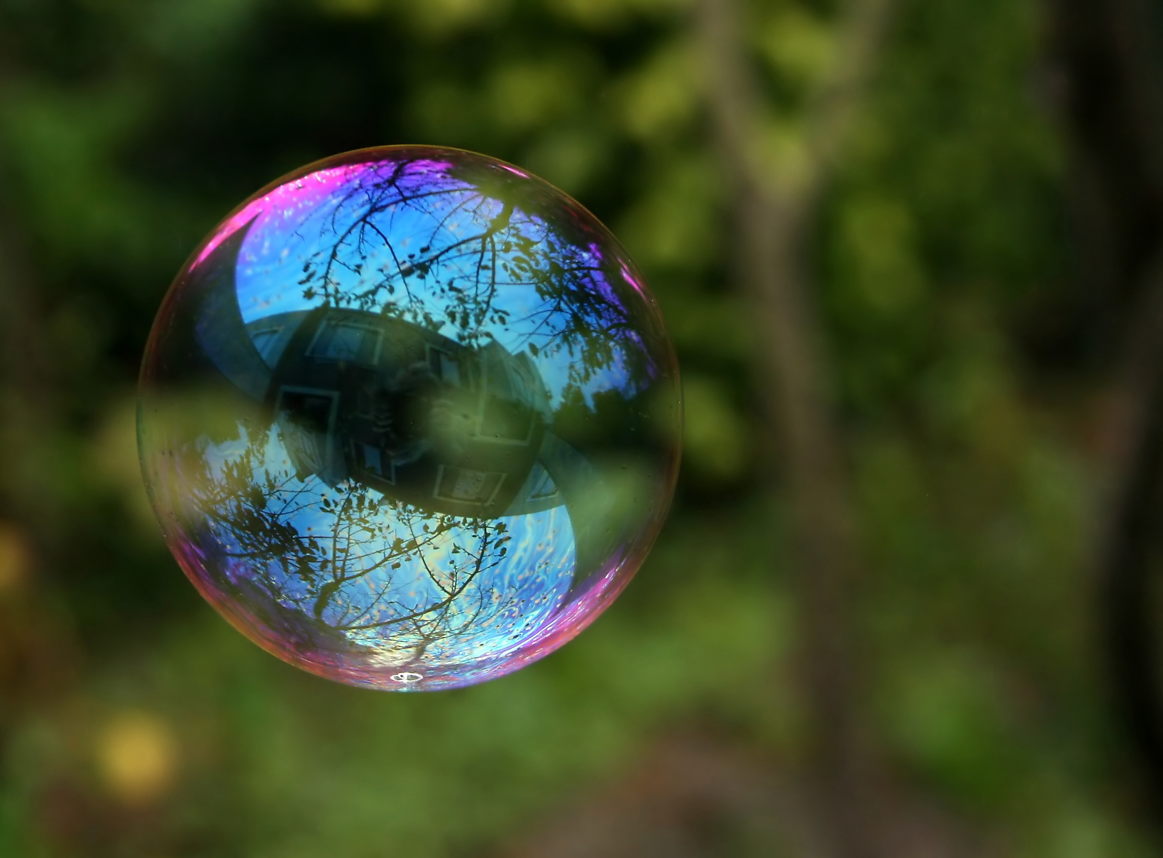
Iridiscence is also seen in a pool of spilled gasoline, on the surface of a CD-ROM, and even on fresh meat. Many insects and animals use iridiscension to create flowers without the presence of appropriate pigments.

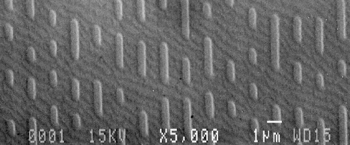
This happens because the iridiscence occurs due to the interaction of light and microscopic structures that are located on the surfaces of all these objects. Both the CD-ROM tracks and the scales of the outer skeleton of an insect (see images below) have the same order of magnitude of the wavelength of light with which they interact. In fact, iridissension was the first phenomenon that allowed to reveal the true wave nature of light. We will not be able to explain and reproduce iridissension without first understanding what the light is, how it works and how it is perceived by the human eye.
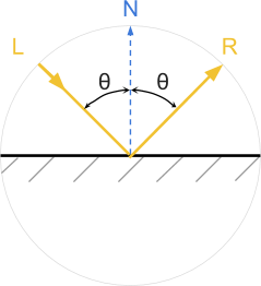
Like many subatomic particles, light simultaneously exhibits the properties of particles and waves. Quite often, light is modeled as the first or second. For most applications, light can be thought of as being made up of trillions of individual particles called photons . For example, most shaders believe that photons behave like tiny billiard balls and are reflected from objects at the angle at which they collided with it (see diagram below).
But light can also be modeled as a wave. Physicists are familiar with this concept, but it is not always known to developers. So let's spend some time trying to figure out what it means for light to exist as a wave.
We all know the ocean waves. Each point on the surface of the ocean has a height. The higher it is from the average value, the higher the wave. If you disturb the surface of the water, the waves begin to spread across the ocean until their energy dissipates.
Light is a wave, but instead of measuring it as a height on the surface of the water, it is defined as the energy that the electromagnetic field has at the desired point. In accordance with this model, light is a disturbance of an electromagnetic field propagating through space. We can imagine a light bulb, either creating a wave, or emitting into the surrounding space a multitude of photons.
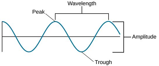
The amount of energy transferred by the photon determines the color of the light. Low energy photons are perceived as red; high energy photons are perceived as purple. Waves have a property similar to particle energy: wavelength . For an intuitive understanding, we can say that this is the distance between the two peaks of the wave.
Light always moves at the same speed (approximately 299,792,458 meters per second), that is, electromagnetic waves propagate at the same speed. Although their speed is constant, the wavelength can be different. High energy photons are short wavelengths. It is the wavelength of light that ultimately determines its color.
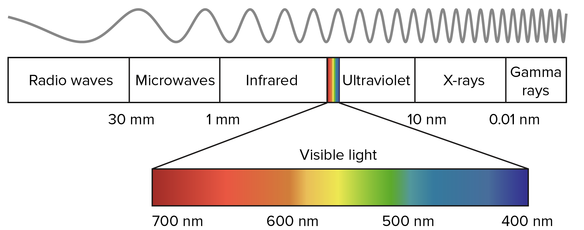
As you can see in the diagram above, a human eye can perceive photons with a wavelength in the range of approximately 700 nanometers to 400 nanometers. A nanometer is a billionth of a meter.
After this brief introduction in the rest of the tutorial, we will focus on understanding iridissention and its implementation in Unity.
From this part we started the tutorial on iridissention. In the remainder of this article, we explore ways to simulate and implement iridiscent reflections on various materials, from bubbles to CD-ROMs, and from spilled gasoline to insects.
Our journey into the world of photorealism requires us to understand not only how light works, but also how we perceive colors. How many colors are there in the rainbow? Why is pink not included in them? Here are just some of the questions that we will address in this part.

In this part, we will introduce the most popular techniques used in computer graphics to recreate the colors of the rainbow. Although this may seem a useless exercise, it actually has a very practical use. Each color of the rainbow corresponds to a specific wavelength of light. Such a correspondence will allow us to simulate physically valid reflections.
In the next part, “Let's improve the rainbow - 2”, we will introduce a new approach that is very well optimized for shaders and at the same time creates the best results at the moment (see below).
Comparison of WebGL versions of all the techniques discussed in this tutorial can be found in Shadertoy .
The retina is the part of the eye that recognizes light. There are cone cells in it that can transmit signals to the brain when they recognize certain wavelengths of light. Light is a wave in an electromagnetic field, so cones operate on the same principles that allow us to recognize radio waves. De facto cones are tiny antennas. If you studied electronics, you should know that the length of the antenna is related to the wavelength it captures. That is why in the human eye there are three different types of cones: short, medium and long. Each type specializes in recognizing a specific wavelength range.
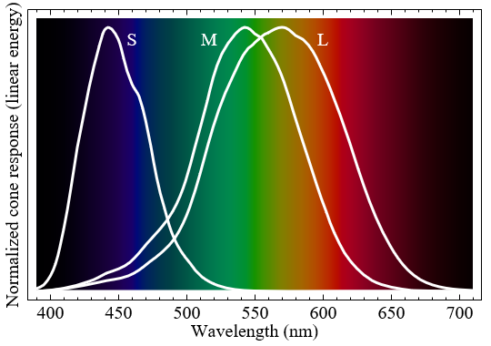
The graph above shows how each type of cones responds to different wavelengths. When one of these types of cones is activated, the brain interprets its signal as color. Despite the fact that such is often said, short, medium and long cones do not correspond to certain colors. More specifically, each type responds differently to different color ranges.
It would be wrong to assume that short, medium, and long cones recognize blue, green, and red. Despite this, many textbooks (and even shaders!) Make such an assumption to create a relatively acceptable approximation of this rather complex phenomenon.
If we want to recreate the physical phenomena that make iridiception possible, then we need to rethink how to store and process colors in a computer. When we create a light source in Unity (or any other game engine), we can set its color as a mixture of three main components: red, green and blue. Although a combination of red, green, and blue can really create all the visible colors, at the most fundamental level, the light works differently.
The light source can be modeled as a constant photon flux. Photons carrying different amounts of energy are perceived by our eye as different colors. However, the "white photon" does not exist. This is the sum of the set of photons, each of which has a different wavelength, which gives the light a white color.
To move on, we need to talk about the "building blocks" of light themselves. When we talk about "wavelengths", then it is worth thinking about specific colors of the rainbow. In this part we will show the various approaches that implement this relationship. As a result, we want to get a function that for a given color returns the perceived color:
In the rest of the post, we will express the wavelengths in nanometers (billionths of a meter). The human eye can perceive light in the range from 400 nm to 700 nm. Wavelengths outside this range exist, but are not perceived as colors.
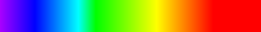
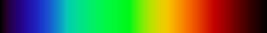
The figure below shows how the human eye perceives waves from 400 nanometers (blue) to 700 nanometers (red) in length.

It is easy to see that the distribution of colors in the visible spectrum is very non-linear. If we plot the corresponding R, G, and B components of the perceived color on the graph for each wavelength, we end up with something like this:

There is no simple function that can fully describe this curve. The simplest and least costly implementation approach would be to use this texture in a shader as a means of binding wavelengths to colors.
The first thing to do is to provide the shader with access to the new texture. We can do this by adding a texture property to the
Our
In our particular case, we do not need to forcibly limit the wavelengths to intervals [400, 700]. If the spectral texture is imported with Repeat: Clamp , all values outside this range will automatically be black.
Texture sampling may seem like a good idea. However, it can slow down the shader significantly. We will see how critical this is in the part about iridissention on CD-ROM, where each pixel will require several texture samples.
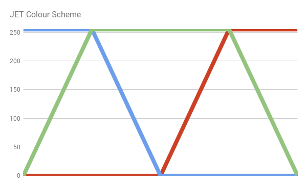
There are several functions that approximate the color distribution of the light spectrum. Probably one of the easiest is the JET color scheme. This default color scheme is used in MATLAB, and it was originally derived by the National Center for Supercomputer Applications for better visualization of fluid jet simulations in astrophysics.

The JET color scheme is a combination of three different curves: blue, green and red. This is clearly seen when dividing the color:
We can easily implement the JET color scheme by writing the equation of the lines that make up the above scheme.
The R, G, and B values of the resulting color are limited to the [0,1] interval using the Cg
It is worth noting that if you want to strictly adhere to the color scheme JET, then the values outside the visible range will not be black.
Another approach to the conversion of wavelengths into visible colors is the scheme proposed by Dan Bruton in the article " Approximate RGB values for Visible Wavelengths ". Similar to what happens in the JET color scheme, Bruton begins with an approximate distribution of perceived colors.
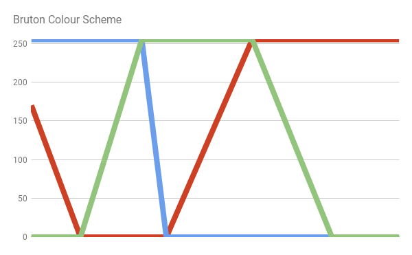
However, its approach better approximates the activity of long cones, which leads to a stronger shade of violet in the lower part of the visible spectrum:
This approach translates into the following code:
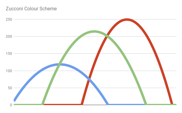
JET and Bruton color schemes use discontinuous functions. Therefore, they create quite sharp color variations. Moreover, outside the visible range they do not become black. In the book “GPU Gems”, this problem is solved by replacing the sharp lines of the previous color schemes with much smoother curves (bumps) . Each bend is an ordinary parabola of the form. y = 1 - x 2 . More specifically
The author of the scheme of Randyma Fernando uses for all components the colors of the parabola, arranged as follows:

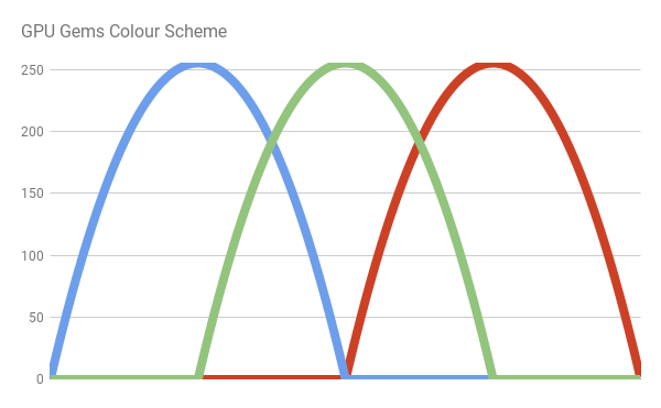
We can write the following code:
An additional advantage of this color scheme is that it does not use texture samples and branching, which makes it one of the best decisions if you prefer speed rather than quality. At the end of this tutorial, I will show a revised version of this color scheme, which provides greater speed, while maintaining high clarity of colors.
One of the most accurate color schemes is the one created by the user Stack Overflow Spektre . He explains his methodology in the post RGB values of visible spectrum , where he samples the blue, green and red components of the real data from the solar spectrum. Then he fills in individual intervals with simple functions. The result is shown in the following diagram:
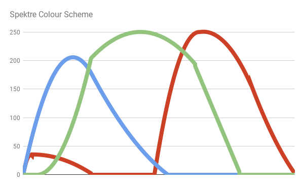
What gives us:
Here is the code:
In this part, we looked at some of the most common techniques for generating rainbow-like patterns in a shader. In the next part, I will introduce you to a new approach to solving this problem.
In the previous section, we analyzed four different ways of converting the wavelengths of the visible range of the electromagnetic spectrum (400-700 nanometers) into their corresponding colors.
In three of these solutions (JET, Bruton and Spektre), if constructions are actively used. For C #, this is standard practice, but in a shader, branching is a bad approach. The only approach that does not use branching is considered in the book GPU Gems. However, it does not provide an optimal approximation of the colors of the visible spectrum.
In this part, I will discuss the optimized version of the color scheme described in the book GPU Gems.
The original color scheme outlined in the book GPU Gems uses three parabolas (called the author bumps ) to recreate the distribution of the R, G, and B components of the rainbow colors.
Each bump is described by the following equation:
Each wavelength w in the range [400, 700] is matched with the normalized value x in the interval [0,1]. Then the components R, G and B of the visible spectrum are set as follows:
All numerical values are selected by the author experimentally. However, you can see how badly they match the true color distribution.
In the first solution, which I arrived at, exactly the same equations were used as in the GPU Gems color scheme. However, I optimized all the numerical values, so that the end color range corresponds as far as possible to the true colors from the visible spectrum.
The result is the following solution:
And leads to a much more realistic result:
Like the original solution, the new approach does not contain branching. Therefore, it is ideal for shaders. The code is as follows:
If we take a closer look at the distribution of colors in the visible spectrum, we note that the parabolas actually cannot repeat the curves of the colors R, G, and B. It will be slightly better to use six parabolas instead of three. Tying two bumps to each main component, we will get a much more correct approximation. The difference is very noticeable in the violet part of the spectrum.

The difference is clearly visible in the violet and orange parts of the spectrum:
Here is the code:
There is no doubt that
In this part, we looked at the new approach to generating shader-like rainbow patterns.
In the first part of the tutorial we met the dual nature of light, which manifests the properties of waves and particles. In this part we will see why both these two aspects are necessary for the emergence of iridissention.
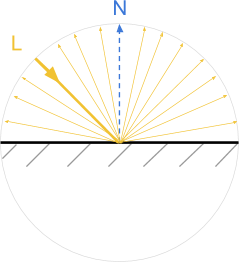
In scientific literature, a ray of light is often mentioned as a way of indicating the path traveled by photons in space and interacting with objects. In most shading models, light is perceived as being created from homogeneous particles, which behave like perfect billiard balls. In the general case, when a beam of light collides with a surface, it is reflected from it at the same deflection angle. Such surfaces behave like perfect mirrors, completely reflecting the light.
Objects rendered in this technique resemble mirrors. Moreover, if the light falls from the direction L , then the observer can see it only when looking from the direction R. This type of reflection is also called specular , which means "mirror-like."
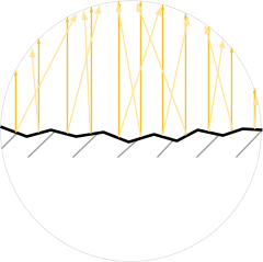
In the real world, most objects reflect light in a different way, called diffuse . When a beam of light falls on a scattering surface, it is more or less evenly scattered in all directions. This gives objects a uniform diffuse color pattern.
In most modern engines (like Unity and Unreal), these two behaviors are modeled using different sets of equations. In my previous tutorial, Physically Based Rendering and Lighting Models, I explained the Lambert and Blinna-Phong reflectivity models, which are used for diffuse and specular reflections, respectively.
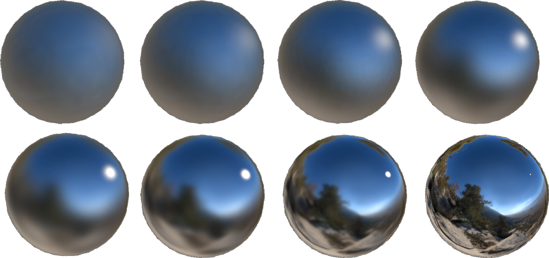
Despite the fact that they look different, the diffuse reflection can be explained through the mirror. No surface is completely flat. A rough surface can be modeled as made from tiny mirrors, each of which is fully characterized by specular reflectivity. The presence of such micrograins leads to scattering of rays in all directions.
The multidirectionality of such microfaces is often modeled by physically accurate shaders using properties such as Smoothness (smoothness) or Roughness (roughness) . You can read more about this on the Unity help page explaining the Smoothness feature of the standard engine shader.
It is very convenient to simulate the rays of light as if they are composed of particles. However, this does not allow us to recreate the behavior, which shows a lot of materials, including iridissentsiyu. Some phenomena can only be fully understood if one accepts the fact that light behaves like a wave in certain conditions.
Most shaders work with light as particles. The result of this tremendous simplification is what undergoes an additive composition . If two beams reach the observer, then their brightness simply adds up. The more rays the surface emits, the brighter it will be.
In the real world, it is not. If two beams of light reach the observer, then the final color depends on how their waves interact with each other. The animation below shows how two simple sinusoidal waves can amplify or dampen each other, depending on their phase .
When two waves coincide in phase , their peaks and valleys ideally coincide: in this case, the final wave is amplified. In the opposite case, they can literally destroy each other. This means that if two beams of light fall on the observer in the correct configuration, he will not receive any light.
Wave interaction may seem like a strange principle. However, we all experienced it in everyday life. The popularizer of science, Derek Muller, explains this well in his video of The Original Double Slit Experiment , where he demonstrates the amplifying and damping interference of water waves.
But how is this related to light and iridissention? The reason for iridissention is the interaction of light waves of different lengths. Some materials can only reflect photons in the right direction, enhancing certain colors and destroying others. As a result of this interaction, we can observe a rainbow.
In the first section of this part, we studied one of the types of interaction of light and matter: reflection. Reflection occurs when light is modeled as a particle. However, if we treat it as a wave, a new set of behaviors will arise. One of them is called diffraction . If all the incident light reaches the surface at one angle, then this is called a plane wave . For example, directional lighting sources in Unity create flat waves. When a plane wave passes through a slot, it is refracted, as shown in the following animation:
If the light passes through two different slits, then two new wave fronts are generated. And as we said above, these new light waves can interact with each other. The animation below shows how the light behaves when there are two such slots. You can see that they actually interact, both amplifying and quenching the rays.
Now we have all the necessary basics to discuss the causes of iridissention.
When a plane wave passes through a slit or is reflected into an unevenness, it refracts, creating a new spherical wave front. This means that the light is scattered in all directions, just as it does with diffuse reflection. If the surface of the material is uneven, then the resulting flat waves are scattered randomly and at the microscopic level, there is no interference pattern.
However, some materials have surface patterns that are replicable on a scale comparable to the wavelength of the incident light. When this happens, the repeatability of the pattern leads to a repetitive and non-random interaction of the fronts of the diffracted waves. The resulting interaction creates a repeating pattern of interference that can be seen at the macroscopic level.
The above effect is called a diffraction grating . Some wavelengths are greatly enhanced, while others are destroyed. Since different wavelengths correspond to different colors, the diffraction grating causes the reflections of some colors to become more pronounced.
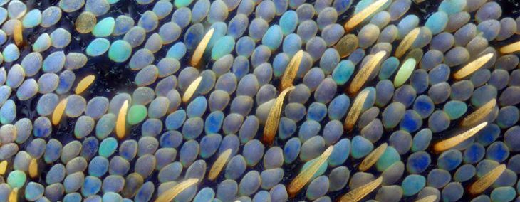
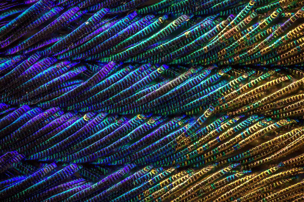
This mechanism ensures the occurrence of iridissencia on surfaces with a repeating pattern. They are often found in nature: the external skeletons of insects and the feathers of birds contain microscopic scales aligned in repetitive patterns. In the picture below you can see an enlarged image of a peacock feather.
In the next part of the tutorial, I will show you how to mathematically simulate a specific type of iridissention. After deriving the equations, they are easy to implement in a shader.
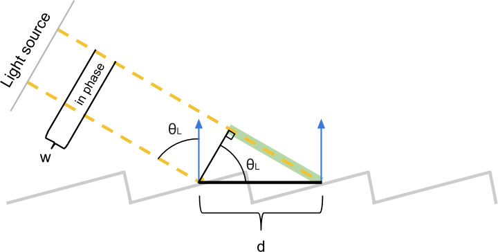
In the previous section, we explained why iridissencia occurs in some materials. Now we have everything we need to start modeling this phenomenon mathematically. Let's start with the fact that we present a material in which there are discontinuities that repeat through known distancesd . In order to derive equations, we denote the angle between the incident rays of light and the surface normal as θL . Let's also imagine that the observer is positioned in such a way that he receives all the reflected rays with an angle θL . Each inhomogeneity scatters light in all directions, so there will always be rays of light falling on the observer, regardless of θL .

Since the discontinuities repeat regularly in increments d nanometers, the scatter pattern itself repeats every dnanometers. It means that there is at least one ray of light coming to the observer from each slot.
The two beams of light shown in the diagram above pass a different distance before reaching the observer. If they start to move, coinciding in phase, then having reached the observer, they may not coincide. To understand how these two beams interact (amplifying or quenching each other), we need to calculate how far they do not coincide in phase when they reach the observer.
These two beams will be exactly the same in phase until the first one hits the surface. The second beam travels an extra distance.x(highlighted in green), after which it also falls to the surface. Using simple trigonometry, we can show that the length of the green segmentx equals d⋅sinθL .
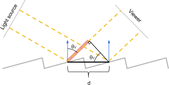
Using a similar construction, we can calculate the extra distance ywhich passes the first ray until the second one hits the surface. In this case, we see thaty=d⋅sinθV .
These two segments xCritical to determining whether the two beams are in phase when they are received by an observer. Their difference measures the difference of the lengths of these two rays. If it is zero, then we know for sure that the two beams coincide in phase, because they essentially covered the same distance.
However, two beams may coincide in phase not only in this case. If the difference in length is an integer multiple of the wavelengthw, they will still be in phase. From a mathematical point of view, two rays coincide in phase if they satisfy the following condition:
Let's take a minute to figure out the meaning of this equation. If the light falls at an angleθL what the observer will see when looking at the material at an angle θV ? All wavelengths w that are integer multiples d(sinθL−sinθV), will interact with the gain, and will manifest themselves strongly in the final reflection. Therefore, it is these colors that the viewer will see.
This effect is visualized by the following diagram, taken from a very interesting discussion of the A complex approach: Iridescence in cycles :
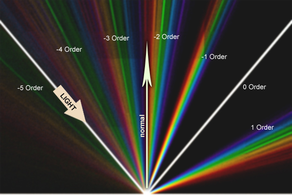
The white beam follows the path traveled by the photons for specular reflection. An observer looking at the material from different angles will see a cyclical rainbow pattern. Each color corresponds to its own wavelength, and the order determines the corresponding integer.n . As you can see, the diffraction grating equation is satisfied even with negative values n because magnitude sinθL−sinθVmay be negative. From a computational point of view, it makes sense to simplify the search space by limiting it to only positive values.n . The new equation, which we will use, has the form:
In this part we will look at the creation of a shader that recreates the rainbow reflections visible on the surface of a CD-ROM or DVD.
In the previous section, we derived equations describing the very nature of the iridiscent reflections exhibited by some surfaces. Iridiscence occurs in materials on whose surfaces there is a repeating pattern, the size of which is comparable to the wavelength of the light reflected by it.
The optical effects that we want to recreate ultimately depend on three factors: the angle between the light source and the surface normal ( direction of light ), the viewing angle of the observer ( direction ), and the distance between the repetitive gaps.
We want the shader to add iridiscent reflections on top of the usual effects that standard material normally creates. Therefore, we will expand the lighting function of the standard surface shader (Standard Surface shader) . If you are not familiar with this procedure, then it is worth exploring my tutorial on Physically Based Rendering and Lighting Models .
The first step is to create a new shader. Since we want to expand the capabilities of a shader that already supports physically accurate lighting, we start with the Standard Surface Shader .

The newly created CD-ROM shader will require a new property: distance dused in the diffraction grating equation. Let's add it to the block
So we will create a new slider in Material Inspector. However, the property
Now we are ready to go.
The first thing we need to do is replace the lighting function of the CD-ROM shader with our own. We can do this by changing the directive
on:
This will force Unity to delegate the calculation of the lighting function called
As you can see from the above code snippet, the new function
However, before moving on, we need to create an additional function to handle global illumination . Since we do not need to change this behavior, our new global illumination function will simply be a proxy function of the standard Unity PBR function:
It is also worth noting that since we use directly
This will be the foundation of our shader. We are finally ready to implement the diffraction grating equations derived in the previous section. In it, we came to the conclusion that the observer sees the iridiscent reflection, which is the sum of all wavelengthswsatisfying the lattice equation :
Where n - integer greater than 0 .
For each pixel value θL(determined by the direction of the light ),θV(determined by the direction of the review ) andd( distance between gaps ) are known. Unknown variables arew and n . The easiest way to cycle through the values nto see which wavelengths satisfy the lattice equation.
When we know which wavelengths contribute to the final iridiscent reflection, we will calculate the corresponding colors and add them. In the “Improve the Rainbow” section, we considered several ways to convert the visible spectrum's wavelengths into colors. In this tutorial we will use
Let's consider the following possible implementation:
In this code snippet we use the values nup to 8. For better results, larger values can be taken, however, this is already enough to take into account a significant part of the iridiscent reflection.
We have the last thing - to calculate
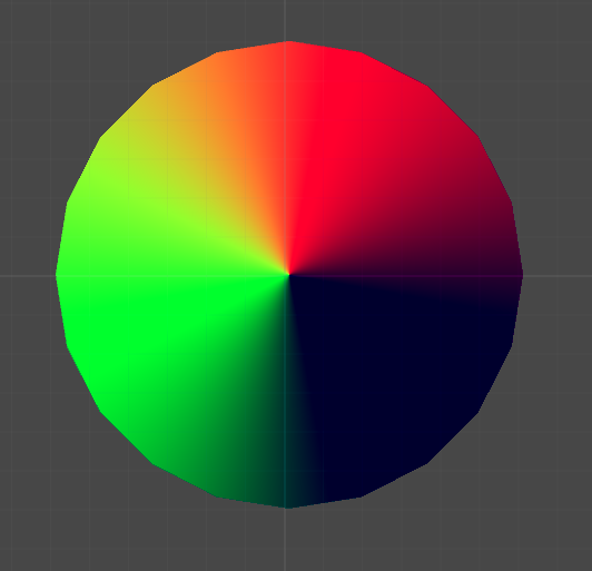
In the previous part of the tutorial, we created the first approximation of iridiscent reflections appearing on the surface of a CD-ROM. It is important to remember that this shader is physically correct. In order to properly simulate the reflection we need, we must make sure that all the CD-ROM tracks are arranged in a circle. So we will create a radial reflection.
The lattice equation we derived has a big limitation: it assumes that all the slots are in the same direction. This is often true for the external skeletons of insects, but the tracks on the surface of a CD-ROM are arranged in a circle. If we implement the solution literally, we get a rather flimsy reflection (the right side of the image).

To solve this problem, we need to consider the local orientation of the slots on the CD-ROM. Using the normal vector does not help, because all the slots have the same normal direction, perpendicular to the disk surface. The local orientation of the slit can be determined using the tangent vector (left side of the upper image).
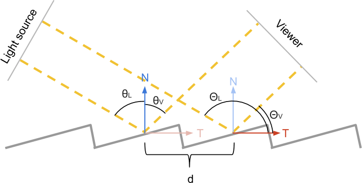
In the diagram above, the direction is normal. N shown in blue, and the direction of the tangent T- red. The angles of the light source and the observer, formed with the direction of the normalN are called θL and θV . Similar angles are relative T - this ΘL and ΘV . As stated above, when used in calculations θL and θV we get a “flat” reflection, because all the slots have the same N . We need to find a way to use ΘL and ΘV, because they correctly correspond to local directions.
While we know that:
Insofar as T and N perpendicular, they have the following property:
This is also very convenient because Cg provides a native implementation of the scalar product. We only need to calculateT .
To finish our shader, we need to calculate the tangent vector T .Usually it is indicated directly in the vertices of the mesh. However, considering how simple the CD-ROM surface is, we can calculate it on our own. It is worth considering that the approach shown in this tutorial is quite simple and will work only if the surface of the CD-ROM mesh has the correct UV scanning.
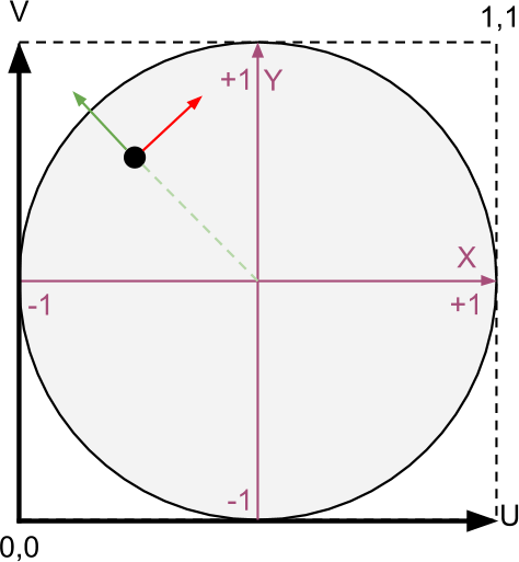
The diagram above shows how the directions of the tangents are calculated. It is assumed that the surface of the disk is UV-unfolded as a quadrilateral with coordinates in the range from (0,0) to (1,1). Knowing this, we reassign the coordinates of each point on the surface of the CD-ROM in the interval from (-1, -1) to (+ 1, + 1). Taking this principle as a basis, we find that the new coordinate of the point also corresponds to the direction outward from the center (green arrow). We can rotate this direction 90 degrees to find a vector that is tangent to the concentric tracks of the CD-ROM (shown in red).
These operations need to be performed as a
It remains for us to only convert the computed tangent from the object space to the world space . The transformation takes into account the position, rotation and scale of the object.
Now we have everything necessary to calculate the effect of color on iridiscent reflection:
The tutorial will consist of the following parts:
- Part 1. The nature of light
- Part 2. Improve the rainbow - 1
- Part 3. Improve the rainbow - 2
- Part 4. Understanding the diffraction grating
- Part 5. Math of a diffraction grating
- Part 6. CD-ROM shader: diffraction grating - 1
- Part 7. CD-ROM shader: diffraction grating - 2
Introduction
Iridiscence is an optical phenomenon in which objects change colors as the lighting angle or angle of view changes. It is because of this effect that the bubbles have such a wide palette of colors.
')
Iridiscence is also seen in a pool of spilled gasoline, on the surface of a CD-ROM, and even on fresh meat. Many insects and animals use iridiscension to create flowers without the presence of appropriate pigments.
This happens because the iridiscence occurs due to the interaction of light and microscopic structures that are located on the surfaces of all these objects. Both the CD-ROM tracks and the scales of the outer skeleton of an insect (see images below) have the same order of magnitude of the wavelength of light with which they interact. In fact, iridissension was the first phenomenon that allowed to reveal the true wave nature of light. We will not be able to explain and reproduce iridissension without first understanding what the light is, how it works and how it is perceived by the human eye.
Nature of light
Like many subatomic particles, light simultaneously exhibits the properties of particles and waves. Quite often, light is modeled as the first or second. For most applications, light can be thought of as being made up of trillions of individual particles called photons . For example, most shaders believe that photons behave like tiny billiard balls and are reflected from objects at the angle at which they collided with it (see diagram below).
But light can also be modeled as a wave. Physicists are familiar with this concept, but it is not always known to developers. So let's spend some time trying to figure out what it means for light to exist as a wave.
We all know the ocean waves. Each point on the surface of the ocean has a height. The higher it is from the average value, the higher the wave. If you disturb the surface of the water, the waves begin to spread across the ocean until their energy dissipates.
Light is a wave, but instead of measuring it as a height on the surface of the water, it is defined as the energy that the electromagnetic field has at the desired point. In accordance with this model, light is a disturbance of an electromagnetic field propagating through space. We can imagine a light bulb, either creating a wave, or emitting into the surrounding space a multitude of photons.
The amount of energy transferred by the photon determines the color of the light. Low energy photons are perceived as red; high energy photons are perceived as purple. Waves have a property similar to particle energy: wavelength . For an intuitive understanding, we can say that this is the distance between the two peaks of the wave.
Light always moves at the same speed (approximately 299,792,458 meters per second), that is, electromagnetic waves propagate at the same speed. Although their speed is constant, the wavelength can be different. High energy photons are short wavelengths. It is the wavelength of light that ultimately determines its color.
As you can see in the diagram above, a human eye can perceive photons with a wavelength in the range of approximately 700 nanometers to 400 nanometers. A nanometer is a billionth of a meter.
How small is the nanometer?
When you try to deal with the smallest scale in which Nature works, it is difficult to imagine the sizes discussed. The average person is about 1.6 meters tall. The thickness of a human hair is about 50 micrometers (50 microns). A micrometer is a millionth part of a meter (1 micron = 0.000001 meters = 10 - 6 meters). A nanometer is one thousandth of a micrometer (1 nm = 0.000000001 meter = 10 - 9 meters). That is, the wavelength of visible light is about one hundredth of the thickness of a human hair.
What's next?
After this brief introduction in the rest of the tutorial, we will focus on understanding iridissention and its implementation in Unity.
- Improve the rainbow. As stated above, different wavelengths of light are perceived by the human eye as different colors. In the next two parts we will deal with how to connect these wavelengths with RGB colors. This step is necessary to recreate iridiscent reflections with a high degree of accuracy. In these parts, I will also present a new approach that will be both physically accurate and efficient in terms of computation.
- Diffraction grating. In parts 4 and 5 of this tutorial, we will look at the diffraction grating . This is the technical name for one of the effects that causes materials to exhibit iridiscent reflections. Despite its "technicality", the derived equation governing this optical phenomenon will be very simple. If you are not interested in the mathematics of a diffraction grating, then you can skip part 5.
- Shader cd rom The core of this tutorial is a CD-ROM shader implementation. In it, the knowledge collected in the previous parts will be used to implement the diffraction grating in Unity. It is an extension of the Unity 5 Standard Surface Shader; which makes this effect both physically correct and photorealistic. With a little effort, you can change it to fit other types of iridiscent reflections based on a diffraction grating.
Summarize
From this part we started the tutorial on iridissention. In the remainder of this article, we explore ways to simulate and implement iridiscent reflections on various materials, from bubbles to CD-ROMs, and from spilled gasoline to insects.
Part 2. Let's improve the rainbow - 1.
Our journey into the world of photorealism requires us to understand not only how light works, but also how we perceive colors. How many colors are there in the rainbow? Why is pink not included in them? Here are just some of the questions that we will address in this part.
Introduction
In this part, we will introduce the most popular techniques used in computer graphics to recreate the colors of the rainbow. Although this may seem a useless exercise, it actually has a very practical use. Each color of the rainbow corresponds to a specific wavelength of light. Such a correspondence will allow us to simulate physically valid reflections.
In the next part, “Let's improve the rainbow - 2”, we will introduce a new approach that is very well optimized for shaders and at the same time creates the best results at the moment (see below).
Comparison of WebGL versions of all the techniques discussed in this tutorial can be found in Shadertoy .
Color perception
The retina is the part of the eye that recognizes light. There are cone cells in it that can transmit signals to the brain when they recognize certain wavelengths of light. Light is a wave in an electromagnetic field, so cones operate on the same principles that allow us to recognize radio waves. De facto cones are tiny antennas. If you studied electronics, you should know that the length of the antenna is related to the wavelength it captures. That is why in the human eye there are three different types of cones: short, medium and long. Each type specializes in recognizing a specific wavelength range.
The graph above shows how each type of cones responds to different wavelengths. When one of these types of cones is activated, the brain interprets its signal as color. Despite the fact that such is often said, short, medium and long cones do not correspond to certain colors. More specifically, each type responds differently to different color ranges.
It would be wrong to assume that short, medium, and long cones recognize blue, green, and red. Despite this, many textbooks (and even shaders!) Make such an assumption to create a relatively acceptable approximation of this rather complex phenomenon.
Spectral color
If we want to recreate the physical phenomena that make iridiception possible, then we need to rethink how to store and process colors in a computer. When we create a light source in Unity (or any other game engine), we can set its color as a mixture of three main components: red, green and blue. Although a combination of red, green, and blue can really create all the visible colors, at the most fundamental level, the light works differently.
The light source can be modeled as a constant photon flux. Photons carrying different amounts of energy are perceived by our eye as different colors. However, the "white photon" does not exist. This is the sum of the set of photons, each of which has a different wavelength, which gives the light a white color.
To move on, we need to talk about the "building blocks" of light themselves. When we talk about "wavelengths", then it is worth thinking about specific colors of the rainbow. In this part we will show the various approaches that implement this relationship. As a result, we want to get a function that for a given color returns the perceived color:
fixed3 spectralColor (float wavelength); In the rest of the post, we will express the wavelengths in nanometers (billionths of a meter). The human eye can perceive light in the range from 400 nm to 700 nm. Wavelengths outside this range exist, but are not perceived as colors.
Why is there no optimal solution?
Earl F. Glynn answered this question best of all:
The search for the final correct correspondence of wavelengths and colors is inevitably doomed to failure. The nature of light is objective, but our perception is not. Cones that perceive certain wavelengths of the visible spectrum have significant variations in different people. Even assuming that all cones work in the same way and constantly for all people, their distribution and number in the retina are mostly random. No two retinas are the same, even in one person.
Finally, color perception depends on how the brain perceives these inputs. As a result, various optical illusions and neuroadaptations arise that make color perception a unique and truly personal experience.
“There is no unique match between wavelength and RGB values. Color is an amazing combination of physics and human perception. ”
The search for the final correct correspondence of wavelengths and colors is inevitably doomed to failure. The nature of light is objective, but our perception is not. Cones that perceive certain wavelengths of the visible spectrum have significant variations in different people. Even assuming that all cones work in the same way and constantly for all people, their distribution and number in the retina are mostly random. No two retinas are the same, even in one person.
Finally, color perception depends on how the brain perceives these inputs. As a result, various optical illusions and neuroadaptations arise that make color perception a unique and truly personal experience.
Spectral map
The figure below shows how the human eye perceives waves from 400 nanometers (blue) to 700 nanometers (red) in length.
It is easy to see that the distribution of colors in the visible spectrum is very non-linear. If we plot the corresponding R, G, and B components of the perceived color on the graph for each wavelength, we end up with something like this:
There is no simple function that can fully describe this curve. The simplest and least costly implementation approach would be to use this texture in a shader as a means of binding wavelengths to colors.
The first thing to do is to provide the shader with access to the new texture. We can do this by adding a texture property to the
Properties block of the new shader. // Properties { ... _SpectralTex("Spectral Map (RGB)",2D) = "white" {} ... } // SubShader { ... CGPROGRAM ... sampler2D _SpectralTex; ... ENDCG ... } Our
spectralColor function simply converts wavelengths in the [400,700] interval to UV coordinates in the [0,1] interval: fixed3 spectral_tex (float wavelength) { // : [400, 700] // u: [0, 1] fixed u = (wavelength -400.0) / 300.0; return tex2D(_SpectralTex, fixed2(u, 0.5)); } In our particular case, we do not need to forcibly limit the wavelengths to intervals [400, 700]. If the spectral texture is imported with Repeat: Clamp , all values outside this range will automatically be black.
Looping textures
Below we will see that in order to reproduce the effects of iridiscence we need to sample a few colors from the rainbow. In some devices, the shader may not support texture sampling in a loop. This is the most important reason why using textures may not be the best approach, especially on mobile platforms.
JET color scheme
Texture sampling may seem like a good idea. However, it can slow down the shader significantly. We will see how critical this is in the part about iridissention on CD-ROM, where each pixel will require several texture samples.
There are several functions that approximate the color distribution of the light spectrum. Probably one of the easiest is the JET color scheme. This default color scheme is used in MATLAB, and it was originally derived by the National Center for Supercomputer Applications for better visualization of fluid jet simulations in astrophysics.
The JET color scheme is a combination of three different curves: blue, green and red. This is clearly seen when dividing the color:
We can easily implement the JET color scheme by writing the equation of the lines that make up the above scheme.
// MATLAB Jet fixed3 spectral_jet(float w) { // w: [400, 700] // x: [0, 1] fixed x = saturate((w - 400.0)/300.0); fixed3 c; if (x < 0.25) c = fixed3(0.0, 4.0 * x, 1.0); else if (x < 0.5) c = fixed3(0.0, 1.0, 1.0 + 4.0 * (0.25 - x)); else if (x < 0.75) c = fixed3(4.0 * (x - 0.5), 1.0, 0.0); else c = fixed3(1.0, 1.0 + 4.0 * (0.75 - x), 0.0); // [0,1] return saturate(c); } The R, G, and B values of the resulting color are limited to the [0,1] interval using the Cg
saturate function. If HDR ( High Dynamic Range Rendering ) is selected for the camera, this is necessary to avoid having colors with components greater than one.It is worth noting that if you want to strictly adhere to the color scheme JET, then the values outside the visible range will not be black.
Bruton Color Scheme
Another approach to the conversion of wavelengths into visible colors is the scheme proposed by Dan Bruton in the article " Approximate RGB values for Visible Wavelengths ". Similar to what happens in the JET color scheme, Bruton begins with an approximate distribution of perceived colors.
However, its approach better approximates the activity of long cones, which leads to a stronger shade of violet in the lower part of the visible spectrum:
This approach translates into the following code:
// fixed3 spectral_bruton (float w) { fixed3 c; if (w >= 380 && w < 440) c = fixed3 ( -(w - 440.) / (440. - 380.), 0.0, 1.0 ); else if (w >= 440 && w < 490) c = fixed3 ( 0.0, (w - 440.) / (490. - 440.), 1.0 ); else if (w >= 490 && w < 510) c = fixed3 ( 0.0, 1.0, -(w - 510.) / (510. - 490.) ); else if (w >= 510 && w < 580) c = fixed3 ( (w - 510.) / (580. - 510.), 1.0, 0.0 ); else if (w >= 580 && w < 645) c = fixed3 ( 1.0, -(w - 645.) / (645. - 580.), 0.0 ); else if (w >= 645 && w <= 780) c = fixed3 ( 1.0, 0.0, 0.0 ); else c = fixed3 ( 0.0, 0.0, 0.0 ); return saturate(c); } Color scheme bump
JET and Bruton color schemes use discontinuous functions. Therefore, they create quite sharp color variations. Moreover, outside the visible range they do not become black. In the book “GPU Gems”, this problem is solved by replacing the sharp lines of the previous color schemes with much smoother curves (bumps) . Each bend is an ordinary parabola of the form. y = 1 - x 2 . More specifically
bump \ left (x \ right) = \ left \ {\ begin {matrix} 0 & \ left | x \ right |> 1 \\ 1-x ^ 2 & \ mathit {otherwise} \ end {matrix} \ right .
bump \ left (x \ right) = \ left \ {\ begin {matrix} 0 & \ left | x \ right |> 1 \\ 1-x ^ 2 & \ mathit {otherwise} \ end {matrix} \ right .
The author of the scheme of Randyma Fernando uses for all components the colors of the parabola, arranged as follows:
We can write the following code:
// GPU Gems inline fixed3 bump3 (fixed3 x) { float3 y = 1 - x * x; y = max(y, 0); return y; } fixed3 spectral_gems (float w) { // w: [400, 700] // x: [0, 1] fixed x = saturate((w - 400.0)/300.0); return bump3 ( fixed3 ( 4 * (x - 0.75), // Red 4 * (x - 0.5), // Green 4 * (x - 0.25) // Blue ) ); } An additional advantage of this color scheme is that it does not use texture samples and branching, which makes it one of the best decisions if you prefer speed rather than quality. At the end of this tutorial, I will show a revised version of this color scheme, which provides greater speed, while maintaining high clarity of colors.
Spektre color scheme
One of the most accurate color schemes is the one created by the user Stack Overflow Spektre . He explains his methodology in the post RGB values of visible spectrum , where he samples the blue, green and red components of the real data from the solar spectrum. Then he fills in individual intervals with simple functions. The result is shown in the following diagram:
What gives us:
Here is the code:
// Spektre fixed3 spectral_spektre (float l) { float r=0.0,g=0.0,b=0.0; if ((l>=400.0)&&(l<410.0)) { float t=(l-400.0)/(410.0-400.0); r= +(0.33*t)-(0.20*t*t); } else if ((l>=410.0)&&(l<475.0)) { float t=(l-410.0)/(475.0-410.0); r=0.14 -(0.13*t*t); } else if ((l>=545.0)&&(l<595.0)) { float t=(l-545.0)/(595.0-545.0); r= +(1.98*t)-( t*t); } else if ((l>=595.0)&&(l<650.0)) { float t=(l-595.0)/(650.0-595.0); r=0.98+(0.06*t)-(0.40*t*t); } else if ((l>=650.0)&&(l<700.0)) { float t=(l-650.0)/(700.0-650.0); r=0.65-(0.84*t)+(0.20*t*t); } if ((l>=415.0)&&(l<475.0)) { float t=(l-415.0)/(475.0-415.0); g= +(0.80*t*t); } else if ((l>=475.0)&&(l<590.0)) { float t=(l-475.0)/(590.0-475.0); g=0.8 +(0.76*t)-(0.80*t*t); } else if ((l>=585.0)&&(l<639.0)) { float t=(l-585.0)/(639.0-585.0); g=0.82-(0.80*t) ; } if ((l>=400.0)&&(l<475.0)) { float t=(l-400.0)/(475.0-400.0); b= +(2.20*t)-(1.50*t*t); } else if ((l>=475.0)&&(l<560.0)) { float t=(l-475.0)/(560.0-475.0); b=0.7 -( t)+(0.30*t*t); } return fixed3(r,g,b); } Conclusion
In this part, we looked at some of the most common techniques for generating rainbow-like patterns in a shader. In the next part, I will introduce you to a new approach to solving this problem.
| Title | Gradient |
| JET | |
| Bruton | |
| GPU Gems | |
| Spektre | |
| Zucconi |  |
| Zucconi6 | |
| Visible spectrum | |
Part 3. Improve the rainbow - 2.
Introduction
In the previous section, we analyzed four different ways of converting the wavelengths of the visible range of the electromagnetic spectrum (400-700 nanometers) into their corresponding colors.
In three of these solutions (JET, Bruton and Spektre), if constructions are actively used. For C #, this is standard practice, but in a shader, branching is a bad approach. The only approach that does not use branching is considered in the book GPU Gems. However, it does not provide an optimal approximation of the colors of the visible spectrum.
| Title | Gradient |
| GPU Gems | |
| Visible spectrum | |
In this part, I will discuss the optimized version of the color scheme described in the book GPU Gems.
Color scheme "Bump"
The original color scheme outlined in the book GPU Gems uses three parabolas (called the author bumps ) to recreate the distribution of the R, G, and B components of the rainbow colors.
Each bump is described by the following equation:
bump \ left (x \ right) = \ left \ {\ begin {matrix} 0 & \ left | x \ right |> 1 \\ 1-x ^ 2 & \ mathit {otherwise} \ end {matrix} \ right .
bump \ left (x \ right) = \ left \ {\ begin {matrix} 0 & \ left | x \ right |> 1 \\ 1-x ^ 2 & \ mathit {otherwise} \ end {matrix} \ right .
Each wavelength w in the range [400, 700] is matched with the normalized value x in the interval [0,1]. Then the components R, G and B of the visible spectrum are set as follows:
R left(x right)=bump left(4 cdotx−0.75 right)
G left(x right)=bump left(4 cdotx−0.5 right)
B left(x right)=bump left(4 cdotx−0.25 right)
All numerical values are selected by the author experimentally. However, you can see how badly they match the true color distribution.
Quality optimization
In the first solution, which I arrived at, exactly the same equations were used as in the GPU Gems color scheme. However, I optimized all the numerical values, so that the end color range corresponds as far as possible to the true colors from the visible spectrum.
The result is the following solution:
And leads to a much more realistic result:
| Title | Gradient |
| GPU Gems | |
| Zucconi | |
| Visible spectrum | |
Like the original solution, the new approach does not contain branching. Therefore, it is ideal for shaders. The code is as follows:
// GPU Gems // inline fixed3 bump3y (fixed3 x, fixed3 yoffset) { float3 y = 1 - x * x; y = saturate(y-yoffset); return y; } fixed3 spectral_zucconi (float w) { // w: [400, 700] // x: [0, 1] fixed x = saturate((w - 400.0)/ 300.0); const float3 cs = float3(3.54541723, 2.86670055, 2.29421995); const float3 xs = float3(0.69548916, 0.49416934, 0.28269708); const float3 ys = float3(0.02320775, 0.15936245, 0.53520021); return bump3y ( cs * (x - xs), ys); } Tell us more about your decision!
To find the optimization algorithm, I used the Python scikit library.
Here are the parameters needed to recreate my results:
Here are the parameters needed to recreate my results:
- Algorithm: L-BFGS-B
- Tolerance: 1 c d o t 10 - 8
- Iterations: 1 c d o t 10 8
- Weighted MSE:
- W R = 0.3
- W G = 0.59
- W B = 0.11
- Fitting
- Image: Linear Visible Spectrum
- Wavelength range: from 400 to 700
- Range resized to: 1024 pixels
- Initial solution:
- C R = 4
- C G = 4
- CB=4
- XR=0.75
- XG=0.5
- XB=0.25
- YR=0
- YG=0
- YB=0
- The final solution:
- CR=3.54541723
- CG=2.86670055
- CB=2.29421995
- XR=0.69548916
- XG=0.49416934
- XB=0.28269708
- YR=0.02320775
- YG=0.15936245
- YB=0.53520021
Improve the rainbow
If we take a closer look at the distribution of colors in the visible spectrum, we note that the parabolas actually cannot repeat the curves of the colors R, G, and B. It will be slightly better to use six parabolas instead of three. Tying two bumps to each main component, we will get a much more correct approximation. The difference is very noticeable in the violet part of the spectrum.
The difference is clearly visible in the violet and orange parts of the spectrum:
| Title | Gradient |
| Zucconi | |
| Zucconi6 | |
| Visible spectrum | |
Here is the code:
// GPU Gems // fixed3 spectral_zucconi6 (float w) { // w: [400, 700] // x: [0, 1] fixed x = saturate((w - 400.0)/ 300.0); const float3 c1 = float3(3.54585104, 2.93225262, 2.41593945); const float3 x1 = float3(0.69549072, 0.49228336, 0.27699880); const float3 y1 = float3(0.02312639, 0.15225084, 0.52607955); const float3 c2 = float3(3.90307140, 3.21182957, 3.96587128); const float3 x2 = float3(0.11748627, 0.86755042, 0.66077860); const float3 y2 = float3(0.84897130, 0.88445281, 0.73949448); return bump3y(c1 * (x - x1), y1) + bump3y(c2 * (x - x2), y2) ; } There is no doubt that
spectral_zucconi6 provides a better approximation of colors without using branching. If speed is important to you, then you can use a simplified version of the algorithm - spectral_zucconi .Summarize
In this part, we looked at the new approach to generating shader-like rainbow patterns.
| Title | Gradient |
| JET | |
| Bruton | |
| GPU Gems | |
| Spektre | |
| Zucconi | |
| Zucconi6 | |
| Visible spectrum | |
Part 4. Understanding the diffraction grating
In the first part of the tutorial we met the dual nature of light, which manifests the properties of waves and particles. In this part we will see why both these two aspects are necessary for the emergence of iridissention.
Reflections: light and mirrors
In scientific literature, a ray of light is often mentioned as a way of indicating the path traveled by photons in space and interacting with objects. In most shading models, light is perceived as being created from homogeneous particles, which behave like perfect billiard balls. In the general case, when a beam of light collides with a surface, it is reflected from it at the same deflection angle. Such surfaces behave like perfect mirrors, completely reflecting the light.
Objects rendered in this technique resemble mirrors. Moreover, if the light falls from the direction L , then the observer can see it only when looking from the direction R. This type of reflection is also called specular , which means "mirror-like."
In the real world, most objects reflect light in a different way, called diffuse . When a beam of light falls on a scattering surface, it is more or less evenly scattered in all directions. This gives objects a uniform diffuse color pattern.
In most modern engines (like Unity and Unreal), these two behaviors are modeled using different sets of equations. In my previous tutorial, Physically Based Rendering and Lighting Models, I explained the Lambert and Blinna-Phong reflectivity models, which are used for diffuse and specular reflections, respectively.
Despite the fact that they look different, the diffuse reflection can be explained through the mirror. No surface is completely flat. A rough surface can be modeled as made from tiny mirrors, each of which is fully characterized by specular reflectivity. The presence of such micrograins leads to scattering of rays in all directions.
The multidirectionality of such microfaces is often modeled by physically accurate shaders using properties such as Smoothness (smoothness) or Roughness (roughness) . You can read more about this on the Unity help page explaining the Smoothness feature of the standard engine shader.
What about reflectivity?
In this section, we said that the diffuse (diffuse) reflection can be fully explained by considering the specular reflection on the surface consisting of multidirectional microfaces. However, this is not entirely true. If the surface shows only a mirror image, this means that with full polishing it will look black. White marble can be considered a good counterexample: no polishing can make it black. Even if we manage to achieve a perfectly smooth surface, white marble will still exhibit a white diffuse reflection component.
And in fact, something else is responsible for this effect. The diffuse surface component also arises from a secondary source: refraction . Light can penetrate the surface of an object, reflect inside it and exit at a different angle (see the figure above). This means that a percentage of the total incident light will be re-emitted from the surface of the material at any arbitrary point and at any angle. This behavior is often called subsurface scattering, and calculations for its simulation are often very costly.
Read more about these effects (and their simulations) in the Basic Theory of Physically Based Rendering article by Marmoset.
Light as a wave
It is very convenient to simulate the rays of light as if they are composed of particles. However, this does not allow us to recreate the behavior, which shows a lot of materials, including iridissentsiyu. Some phenomena can only be fully understood if one accepts the fact that light behaves like a wave in certain conditions.
Most shaders work with light as particles. The result of this tremendous simplification is what undergoes an additive composition . If two beams reach the observer, then their brightness simply adds up. The more rays the surface emits, the brighter it will be.
In the real world, it is not. If two beams of light reach the observer, then the final color depends on how their waves interact with each other. The animation below shows how two simple sinusoidal waves can amplify or dampen each other, depending on their phase .
Animation
When two waves coincide in phase , their peaks and valleys ideally coincide: in this case, the final wave is amplified. In the opposite case, they can literally destroy each other. This means that if two beams of light fall on the observer in the correct configuration, he will not receive any light.
Wave interaction may seem like a strange principle. However, we all experienced it in everyday life. The popularizer of science, Derek Muller, explains this well in his video of The Original Double Slit Experiment , where he demonstrates the amplifying and damping interference of water waves.
But how is this related to light and iridissention? The reason for iridissention is the interaction of light waves of different lengths. Some materials can only reflect photons in the right direction, enhancing certain colors and destroying others. As a result of this interaction, we can observe a rainbow.
Diffraction
In the first section of this part, we studied one of the types of interaction of light and matter: reflection. Reflection occurs when light is modeled as a particle. However, if we treat it as a wave, a new set of behaviors will arise. One of them is called diffraction . If all the incident light reaches the surface at one angle, then this is called a plane wave . For example, directional lighting sources in Unity create flat waves. When a plane wave passes through a slot, it is refracted, as shown in the following animation:
Animation
If the light passes through two different slits, then two new wave fronts are generated. And as we said above, these new light waves can interact with each other. The animation below shows how the light behaves when there are two such slots. You can see that they actually interact, both amplifying and quenching the rays.
Animation
Now we have all the necessary basics to discuss the causes of iridissention.
Diffraction grating
When a plane wave passes through a slit or is reflected into an unevenness, it refracts, creating a new spherical wave front. This means that the light is scattered in all directions, just as it does with diffuse reflection. If the surface of the material is uneven, then the resulting flat waves are scattered randomly and at the microscopic level, there is no interference pattern.
However, some materials have surface patterns that are replicable on a scale comparable to the wavelength of the incident light. When this happens, the repeatability of the pattern leads to a repetitive and non-random interaction of the fronts of the diffracted waves. The resulting interaction creates a repeating pattern of interference that can be seen at the macroscopic level.
The above effect is called a diffraction grating . Some wavelengths are greatly enhanced, while others are destroyed. Since different wavelengths correspond to different colors, the diffraction grating causes the reflections of some colors to become more pronounced.
This mechanism ensures the occurrence of iridissencia on surfaces with a repeating pattern. They are often found in nature: the external skeletons of insects and the feathers of birds contain microscopic scales aligned in repetitive patterns. In the picture below you can see an enlarged image of a peacock feather.
Summarize
In the next part of the tutorial, I will show you how to mathematically simulate a specific type of iridissention. After deriving the equations, they are easy to implement in a shader.
Part 5. Mathematics of the diffraction grating.
Introduction
In the previous section, we explained why iridissencia occurs in some materials. Now we have everything we need to start modeling this phenomenon mathematically. Let's start with the fact that we present a material in which there are discontinuities that repeat through known distancesd . In order to derive equations, we denote the angle between the incident rays of light and the surface normal as θL . Let's also imagine that the observer is positioned in such a way that he receives all the reflected rays with an angle θL . Each inhomogeneity scatters light in all directions, so there will always be rays of light falling on the observer, regardless of θL .
Since the discontinuities repeat regularly in increments d nanometers, the scatter pattern itself repeats every dnanometers. It means that there is at least one ray of light coming to the observer from each slot.
Derivation of equations
The two beams of light shown in the diagram above pass a different distance before reaching the observer. If they start to move, coinciding in phase, then having reached the observer, they may not coincide. To understand how these two beams interact (amplifying or quenching each other), we need to calculate how far they do not coincide in phase when they reach the observer.
These two beams will be exactly the same in phase until the first one hits the surface. The second beam travels an extra distance.x(highlighted in green), after which it also falls to the surface. Using simple trigonometry, we can show that the length of the green segmentx equals d⋅sinθL .
Using a similar construction, we can calculate the extra distance ywhich passes the first ray until the second one hits the surface. In this case, we see thaty=d⋅sinθV .
These two segments xCritical to determining whether the two beams are in phase when they are received by an observer. Their difference measures the difference of the lengths of these two rays. If it is zero, then we know for sure that the two beams coincide in phase, because they essentially covered the same distance.
However, two beams may coincide in phase not only in this case. If the difference in length is an integer multiple of the wavelengthw, they will still be in phase. From a mathematical point of view, two rays coincide in phase if they satisfy the following condition:
dsinθL−dsinθV=n⋅w
sinθL−sinθV=n⋅wd
Visualization
Let's take a minute to figure out the meaning of this equation. If the light falls at an angleθL what the observer will see when looking at the material at an angle θV ? All wavelengths w that are integer multiples d(sinθL−sinθV), will interact with the gain, and will manifest themselves strongly in the final reflection. Therefore, it is these colors that the viewer will see.
This effect is visualized by the following diagram, taken from a very interesting discussion of the A complex approach: Iridescence in cycles :
The white beam follows the path traveled by the photons for specular reflection. An observer looking at the material from different angles will see a cyclical rainbow pattern. Each color corresponds to its own wavelength, and the order determines the corresponding integer.n . As you can see, the diffraction grating equation is satisfied even with negative values n because magnitude sinθL−sinθVmay be negative. From a computational point of view, it makes sense to simplify the search space by limiting it to only positive values.n . The new equation, which we will use, has the form:
|sinθL−sinθV|=n⋅wd
Part 6. CD-ROM shader: diffraction grating - 1
In this part we will look at the creation of a shader that recreates the rainbow reflections visible on the surface of a CD-ROM or DVD.
Introduction
In the previous section, we derived equations describing the very nature of the iridiscent reflections exhibited by some surfaces. Iridiscence occurs in materials on whose surfaces there is a repeating pattern, the size of which is comparable to the wavelength of the light reflected by it.
The optical effects that we want to recreate ultimately depend on three factors: the angle between the light source and the surface normal ( direction of light ), the viewing angle of the observer ( direction ), and the distance between the repetitive gaps.
We want the shader to add iridiscent reflections on top of the usual effects that standard material normally creates. Therefore, we will expand the lighting function of the standard surface shader (Standard Surface shader) . If you are not familiar with this procedure, then it is worth exploring my tutorial on Physically Based Rendering and Lighting Models .
Creating a surface shader
The first step is to create a new shader. Since we want to expand the capabilities of a shader that already supports physically accurate lighting, we start with the Standard Surface Shader .
The newly created CD-ROM shader will require a new property: distance dused in the diffraction grating equation. Let's add it to the block
Properties, which should look like this: Properties { _Color ("Color", Color) = (1,1,1,1) _MainTex ("Albedo (RGB)", 2D) = "white" {} _Glossiness ("Smoothness", Range(0,1)) = 0.5 _Metallic ("Metallic", Range(0,1)) = 0.0 _Distance ("Grating distance", Range(0,10000)) = 1600 // nm } So we will create a new slider in Material Inspector. However, the property
_Distancestill needs to be associated with a variable in the section CGPROGRAM: float _Distance; Now we are ready to go.
Changing the lighting function
The first thing we need to do is replace the lighting function of the CD-ROM shader with our own. We can do this by changing the directive
#pragmahere: #pragma surface surf Standard fullforwardshadows on:
#pragma surface surf Diffraction fullforwardshadows This will force Unity to delegate the calculation of the lighting function called
LightingDiffraction. It is important to understand that we want to expand the functionality of this surface shader, and not override it . Therefore, our new lighting function will begin with calling the standard Unity PBR lighting function: #include "UnityPBSLighting.cginc" inline fixed4 LightingDiffraction(SurfaceOutputStandard s, fixed3 viewDir, UnityGI gi) { // fixed4 pbr = LightingStandard(s, viewDir, gi); // < > return pbr; } As you can see from the above code snippet, the new function
LightingDiffractionsimply calls LightingStandardand returns its value. If we compile the shader now, we will not see any difference in the way materials are rendered.However, before moving on, we need to create an additional function to handle global illumination . Since we do not need to change this behavior, our new global illumination function will simply be a proxy function of the standard Unity PBR function:
void LightingDiffraction_GI(SurfaceOutputStandard s, UnityGIInput data, inout UnityGI gi) { LightingStandard_GI(s, data, gi); } It is also worth noting that since we use directly
LightingStandardand LightingDiffraction_GI, then we need to include it in our shader UnityPBSLighting.cginc.The implementation of the diffraction grating
This will be the foundation of our shader. We are finally ready to implement the diffraction grating equations derived in the previous section. In it, we came to the conclusion that the observer sees the iridiscent reflection, which is the sum of all wavelengthswsatisfying the lattice equation :
|sinθL−sinθV|=n⋅wd
Where n - integer greater than 0 .
For each pixel value θL(determined by the direction of the light ),θV(determined by the direction of the review ) andd( distance between gaps ) are known. Unknown variables arew and n . The easiest way to cycle through the values nto see which wavelengths satisfy the lattice equation.
When we know which wavelengths contribute to the final iridiscent reflection, we will calculate the corresponding colors and add them. In the “Improve the Rainbow” section, we considered several ways to convert the visible spectrum's wavelengths into colors. In this tutorial we will use
spectral_zucconi6it because it provides the best approximation with the least computational cost.Let's consider the following possible implementation:
inline fixed4 LightingDiffraction(SurfaceOutputStandard s, fixed3 viewDir, UnityGI gi) { // fixed4 pbr = LightingStandard(s, viewDir, gi); // fixed3 color = 0; for (int n = 1; n <= 8; n++) { float wavelength = abs(sin_thetaL - sin_thetaV) * d / n; color += spectral_zucconi6(wavelength); } color = saturate(color); // pbr.rgb += color; return pbr; } In this code snippet we use the values nup to 8. For better results, larger values can be taken, however, this is already enough to take into account a significant part of the iridiscent reflection.
We have the last thing - to calculate
sin_thetaLand sin_thetaV. To do this, we need to introduce another concept: the tangent vector . In the next section, we will learn how to calculate it.Part 7. CD-ROM shader: diffraction grating - 2
Introduction
In the previous part of the tutorial, we created the first approximation of iridiscent reflections appearing on the surface of a CD-ROM. It is important to remember that this shader is physically correct. In order to properly simulate the reflection we need, we must make sure that all the CD-ROM tracks are arranged in a circle. So we will create a radial reflection.
Slot orientation
The lattice equation we derived has a big limitation: it assumes that all the slots are in the same direction. This is often true for the external skeletons of insects, but the tracks on the surface of a CD-ROM are arranged in a circle. If we implement the solution literally, we get a rather flimsy reflection (the right side of the image).
To solve this problem, we need to consider the local orientation of the slots on the CD-ROM. Using the normal vector does not help, because all the slots have the same normal direction, perpendicular to the disk surface. The local orientation of the slit can be determined using the tangent vector (left side of the upper image).
In the diagram above, the direction is normal. N shown in blue, and the direction of the tangent T- red. The angles of the light source and the observer, formed with the direction of the normalN are called θL and θV . Similar angles are relative T - this ΘL and ΘV . As stated above, when used in calculations θL and θV we get a “flat” reflection, because all the slots have the same N . We need to find a way to use ΘL and ΘV, because they correctly correspond to local directions.
While we know that:
N⋅L=cosθLN⋅V=cosθV
T⋅L=cosΘLT⋅V=cosΘV
Insofar as T and N perpendicular, they have the following property:
T⋅L=cosΘL=sinθL
T ⋅ V = cos Θ V = sin θ V
This is also very convenient because Cg provides a native implementation of the scalar product. We only need to calculateT .
Where does cosine come from?
: 1. . , — .
, . , . .
, . , . .
Tangent vector calculation
To finish our shader, we need to calculate the tangent vector T .Usually it is indicated directly in the vertices of the mesh. However, considering how simple the CD-ROM surface is, we can calculate it on our own. It is worth considering that the approach shown in this tutorial is quite simple and will work only if the surface of the CD-ROM mesh has the correct UV scanning.
The diagram above shows how the directions of the tangents are calculated. It is assumed that the surface of the disk is UV-unfolded as a quadrilateral with coordinates in the range from (0,0) to (1,1). Knowing this, we reassign the coordinates of each point on the surface of the CD-ROM in the interval from (-1, -1) to (+ 1, + 1). Taking this principle as a basis, we find that the new coordinate of the point also corresponds to the direction outward from the center (green arrow). We can rotate this direction 90 degrees to find a vector that is tangent to the concentric tracks of the CD-ROM (shown in red).
These operations need to be performed as a
surfshader, because UV coordinates are not available in the lighting function LightingDiffraction. // IN.uv_MainTex: [ 0, +1] // uv: [-1, +1] fixed2 uv = IN.uv_MainTex * 2 -1; fixed2 uv_orthogonal = normalize(uv); fixed3 uv_tangent = fixed3(-uv_orthogonal.y, 0, uv_orthogonal.x); It remains for us to only convert the computed tangent from the object space to the world space . The transformation takes into account the position, rotation and scale of the object.
worldTangent = normalize( mul(unity_ObjectToWorld, float4(uv_tangent, 0)) ); How to transfer the direction of the tangent to the lighting function?
, : . .
LightingDiffraction . worldTangent, surf . , , ., : . .
worldTangent , surf LightingDiffraction .How to switch between coordinate spaces?
. . .
, . , , , ,
, . , , , ,
unity_ObjectToWorld . Unity, _Object2World .We put everything together
Now we have everything necessary to calculate the effect of color on iridiscent reflection:
inline fixed4 LightingDiffraction(SurfaceOutputStandard s, fixed3 viewDir, UnityGI gi) { // fixed4 pbr = LightingStandard(s, viewDir, gi); // --- --- float3 L = gi.light.dir; float3 V = viewDir; float3 T = worldTangent; float d = _Distance; float cos_ThetaL = dot(L, T); float cos_ThetaV = dot(V, T); float u = abs(cos_ThetaL - cos_ThetaV); if (u == 0) return pbr; // fixed3 color = 0; for (int n = 1; n <= 8; n++) { float wavelength = u * d / n; color += spectral_zucconi6(wavelength); } color = saturate(color); // pbr.rgb += color; return pbr; } How does this relate to rainbow?
Source: https://habr.com/ru/post/346852/
All Articles