Creating parametric database objects in nanoCAD Mechanics

In nanoCAD Mechanics, there is a base of standard products, many of the elements of which are parametric objects and are interconnected by certain dependencies. These dependencies are determined by the standards in which the elements are executed.
A parametric object is an element with a geometry controlled by parameters.
The Object Wizard module in nanoCAD Mechanics allows you to create objects whose parameters are associated with certain dependencies, not only within the object, but also with the parameters of other database objects. This provides the ability to generate, through parameters, various executions or types of the same object, as well as to manage multi-component assemblies, creating different variations of the same unit or product as a whole.
The proposed series of practical materials describes some of the features of the parametrization module in nanoCAD Mechanics and can serve as a short tutorial on the creation of parametric elements.
Part 1. Preparation of the geometry of the object. Creating a base item
To create a parametric element using standard nanoCAD tools, we draw a simple geometric object consisting of primitives. An object can also be imported in * .dwg format from another system (Fig. 1).
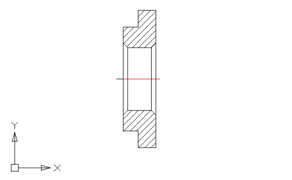
Fig. one
When creating hatching, select Type - Of lines . This will be needed later for parametric recognition of geometry when creating a base object (Fig. 2).

Fig. 2
In order for the hatching to be displayed correctly, you should set a thin line type (Line type: 2). To do this, call the menu command Mechanics - Standard - MechWizard - Set the parameter . This command can be activated by the corresponding button on the ESKD MechWizard toolbar (Fig. 3).
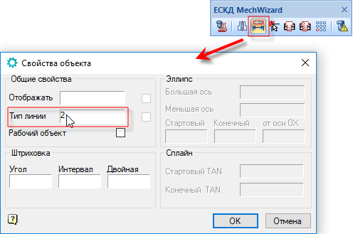
Fig. 3
Hereinafter, for the convenience of working with the Object Wizard , it is recommended to use the ESKD MechWizard panel . To display the panel, open the View menu and go to Panel - Mechanics - ESKD MechWizard (Fig. 4).
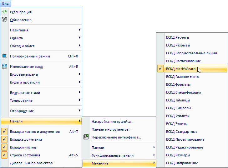
Fig. four
Draw the second view and dimension the dimensions. In the designation of sizes using Latin letters. It is important that all dimensions denoting the same geometric elements on different types have the same designations. (Fig. 5).

Fig. five
The “l” parameter in the first view is required to create an insertion point. To define it, create an additional segment. Set the segment parameter. To do this, call the menu command Mechanics - Standard - MechWizard - Set the parameter (or press the corresponding button on the MechWizard panel), specify the segment and press Enter . In the Object Properties window that opens, enable the Work object option and click OK (Fig. 6).

Fig. 6
Now that the element geometry has been created and the defining dimensions have been set, we will create an object in the element base. To do this, call the Object Wizard via the menu Mechanics - Standard - MechWizard - Object Wizard or by clicking the Object Wizard button on the MechWizard panel  .
.
In the Object Object Wizard window that opens, select the Object - New menu or click the New Object button. In the New object window, select the database folder in which the object will be placed (in this case, Custom), fill in the Name field and click OK (Fig. 7).

Fig. 7
The object is created, now add the geometry. In the Object Wizard, right-click (RMB) on the Execution branch and select Add Performance from the context menu. Clicking the RMB in the workspace of the Wizard , create another view (Fig. 8).

Fig. eight
Denote the first view as Front View (to do this, select it and click on the corresponding view display button), and denote the second view as Side View (Fig. 9).

Fig. 9
Now assign the corresponding geometry to the views created in the Object Wizard. To do this, click RMB on the form and from the context menu, select Parametric type recognition. The system will enter Mode. Select the object, then select Enter in the context menu or press Enter on the keyboard (Fig. 10).

Fig. ten
To complete the operation, you need to select the insertion point (the left edge of the segment with the size “l”). If recognition is successful, a corresponding message will appear (Fig. 11).

Fig. eleven
Similar actions are performed for the side view. As the insertion point, we specify the center of the axes of the object (Fig. 12).
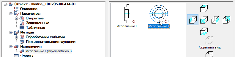
Fig. 12
In the object tree, go to the Script branch. The program code of the object description will open in the workspace, where the main functions are displayed by default (Fig. 13).
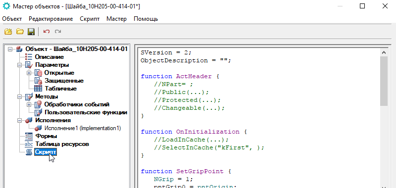
Fig. 13
So, we looked at how in nanoCAD Mechanics, using the Object Wizard, you can create a base object and connect geometry to it.
In the next part, we will analyze how to parameterize this object using the Script Wizard , as well as using the equivalent object.
')
Source: https://habr.com/ru/post/346704/
All Articles